ASA 7.x/PIX 6.x and Above: Open/Block the Ports Configuration Example
Available Languages
Contents
Introduction
This document provides a sample configuration for how to open or block the ports for the various type of traffic, such as http or ftp, in the Security Appliance.
Note: The terms "opening the port" and "allowing the port" deliver the same meaning. Similarly, "blocking the port" and "restricting the port" also deliver the same meaning.
Prerequisites
Requirements
This document assumes that PIX/ASA is configured and works properly.
Components Used
The information in this document is based on these software and hardware versions:
-
Cisco 5500 Series Adaptive Security Appliance (ASA) that runs version 8.2(1)
-
Cisco Adaptive Security Device Manager (ASDM) version 6.3(5)
The information in this document was created from the devices in a specific lab environment. All of the devices used in this document started with a cleared (default) configuration. If your network is live, make sure that you understand the potential impact of any command.
Related Products
This configuration can also be used with the Cisco 500 Series PIX Firewall Appliance with software version 6.x and above.
Conventions
Refer to the Cisco Technical Tips Conventions for more information on document conventions.
Configure
Each interface must have a security level from 0 (lowest) to 100 (highest). For example, you must assign your most secure network, such as the inside host network, to level 100. While the outside network that is connected to the Internet can be level 0, other networks, such as DMZs, can be positioned in between. You can assign multiple interfaces to the same security level.
By default, all ports are blocked on the outside interface (security level 0), and all ports are open on the inside interface (security level 100) of the security appliance. In this way, all outbound traffic can pass through the security appliance without any configuration, but inbound traffic can be allowed by the configuration of the access list and static commands in the security appliance.
Note: In general, all ports are blocked from the Lower Security Zone to the Higher Security Zone, and all ports are open from the Higher Security Zone to the Lower Security Zone providing that the stateful inspection is enabled for both inbound and outbound traffic.
This section consists of the sub-sections as shown:
In this section, you are presented with the information to configure the features described in this document.
Note: Use the Command Lookup Tool (registered customers only) to obtain more information on the commands used in this section.
Network Diagram
This document uses this network setup:
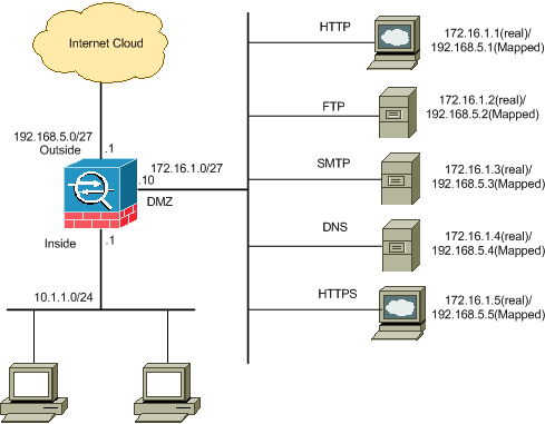
Blocking the Ports Configuration
The security appliance allows any outbound traffic unless it is explicitly blocked by an extended access list.
An access list is made up of one or more Access Control Entries. Dependent upon the access list type, you can specify the source and destination addresses, protocol, ports (for TCP or UDP), ICMP type (for ICMP), or EtherType.
Note: For connectionless protocols, such as ICMP, the security appliance establishes unidirectional sessions, so you either need access lists to allow ICMP in both directions (by the application of access lists to the source and destination interfaces), or you need to enable the ICMP inspection engine. The ICMP inspection engine treats ICMP sessions as bidirectional connections.
Complete these steps in order to block the ports, which usually apply to traffic that originates from the inside (higher security zone) to the DMZ (lower security zone) or the DMZ to the outside.
-
Create an Access Control List in such a way that you block the specified port traffic.
access-list <name> extended deny <protocol> <source-network/source IP>
<source-netmask> <destination-network/destination IP>
<destinamtion-netmask> eq <port number>

access-list <name> extended permit ip any any
-
Then bind the access-list with the access-group command in order to be active.
access-group <access list name> in interface <interface name>
Examples:
-
Block the HTTP port traffic: In order to block the inside network 10.1.1.0 from access to the http (web server) with IP 172.16.1.1 placed in the DMZ network, create an ACL as shown:
ciscoasa(config)#access-list 100 extended deny tcp 10.1.1.0 255.255.255.0
   host 172.16.1.1  eq 80
ciscoasa(config)#access-list 100 extended permit ip any any
ciscoasa(config)#access-group 100 in interface inside
Note: Use no followed by the access list commands in order to remove the port blocking.
-
Block the FTP port traffic: In order to block the inside network 10.1.1.0 from access to the FTP (file server) with IP 172.16.1.2 placed in the DMZ network, create an ACL as shown:
ciscoasa(config)#access-list 100 extended deny tcp 10.1.1.0 255.255.255.0
   host 172.16.1.2  eq 21
ciscoasa(config)#access-list 100 extended permit ip any any
ciscoasa(config)#access-group 100 in interface inside
Note: Refer to IANA ports in order to learn more information about port assignments.
The step-by-step configuration to perform this through the ASDM is shown in this section.
-
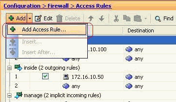
Go to Configuration > Firewall > Access Rules. Click Add Access Rule to create the access-list.
-
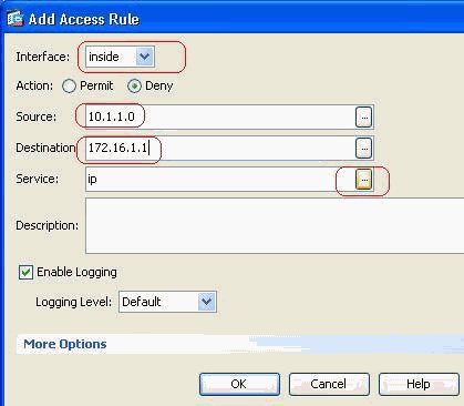
Define the source and destination and the action of the access-rule along with the interface that this access rule will be associated. Select the details to choose the specific port to block.
-
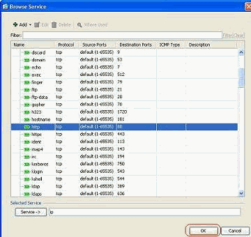
Choose http from the list of available ports, then click OK to revert back to the Add Access Rule window.
-
Click OK to complete the configuration of the access rule.
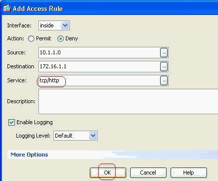
-
Click Insert After to add an access rule to the same access-list.
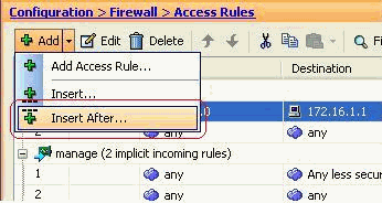
-
Permit the traffic from "any" to "any" to prevent the "Implicit deny". Then, click OK to complete adding this access rule.
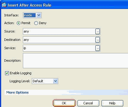
-
The configured access-list can be seen in the Access Rules tab. Click Apply to send this configuration to the Security appliance.
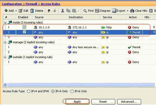
The configuration sent from the ASDM results in this set of commands on the Command Line Interface (CLI) of the ASA.
access-list inside_access_in extended deny tcp host 10.1.1.0 host 172.16.1.1 eq www
access-list inside_access_in extended permit ip any any
access-group inside_access_in in interface inside
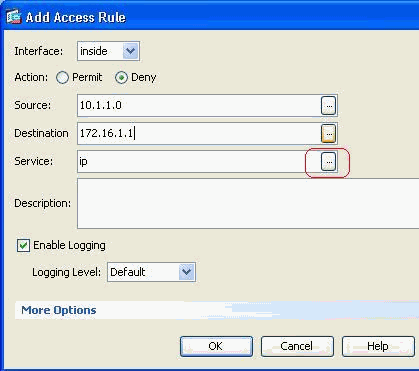
Through these steps, example 1 has been performed through ASDM to block the 10.1.1.0 network from accessing the web server, 172.16.1.1. Example 2 can also be achieved in the same way to block the entire 10.1.1.0 network from accessing the FTP server, 172.16.1.2. The only difference will be at the point of choosing the port.
Note: This access rule configuration for example 2 is assumed to be a fresh configuration.
-
Define the access rule for blocking FTP traffic, then click the Details tab to choose the destination port.
-
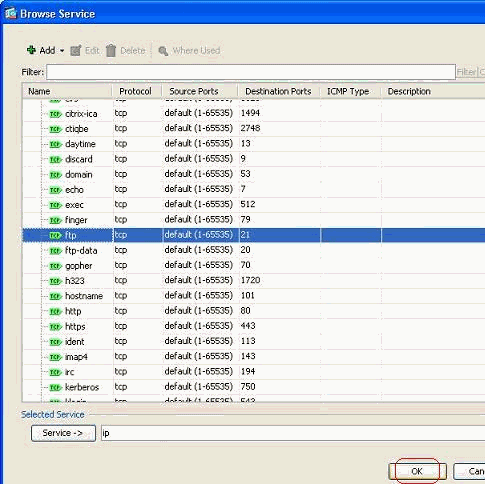
Choose the ftp port and click OK to revert back to the Add Access Rule window.
-
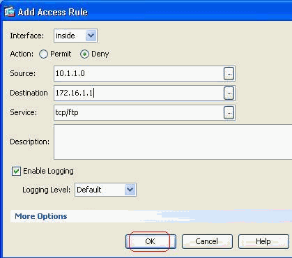
Click OK to complete the configuration of the access rule.
-
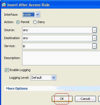
Add another access rule to permit any other traffic. Otherwise, the Implicit Deny rule will block all the traffic on this interface.
-
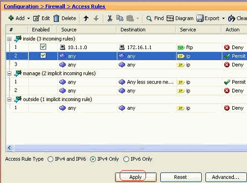
The complete access list configuration looks like this under the Access Rules tab.
-
Click Apply to send the configuration to the ASA. The equivalent CLI configuration looks like this:
access-list inside_access_in extended deny tcp host 10.1.1.0 host 172.16.1.1 eq ftp
access-list inside_access_in extended permit ip any any
access-group inside_access_in in interface inside
Opening the Ports Configuration
The security appliance does not allow any inbound traffic unless it is explicitly permitted by an extended access list.
If you want to allow an outside host to access an inside host, you can apply an inbound access list on the outside interface. You need to specify the translated address of the inside host in the access list because the translated address is the address that can be used on the outside network. Complete these steps in order to open the ports from the lower security zone to the higher security zone. For example, allow the traffic from the outside (lower security zone) to the inside interface (higher security zone) or the DMZ to the inside interface.
-
Static NAT creates a fixed translation of a real address to a mapped address. This mapped address is an address that hosts on the Internet and can be used to access the application server on the DMZ without the need to know the real address of the server.
static (real_ifc,mapped_ifc) mapped_ip {real_ip [netmask mask] |
   access-list access_list_name | interface}
Refer to the Static NAT section of the Command reference for PIX/ASA in order to learn more information.
-
Create an ACL in order to permit the specific port traffic.
access-list <name> extended permit <protocol> <source-network/source IP>
<source-netmask> <destination-network/destination IP>
<destinamtion-netmask> eq <port number>
-
Bind the access-list with the access-group command in order to be active.
access-group <access-list name> in interface <interface name>
Examples:
-
Open the SMTP port traffic: Open the port tcp 25 in order to allow the hosts from the outside (Internet) to access the mail server placed in the DMZ network.
The Static command maps the outside address 192.168.5.3 to the real DMZ address 172.16.1.3.
ciscoasa(config)#static (DMZ,Outside) 192.168.5.3 172.16.1.3
 netmask 255.255.255.255
ciscoasa(config)#access-list 100 extended permit tcp
 any host 192.168.5.3 eq 25
ciscoasa(config)#access-group 100 in interface outside
-
Open the HTTPS port traffic: Open the port tcp 443 in order to allow the hosts from the outside (Internet) to access the web server (secure) placed in the DMZ network.
ciscoasa(config)#static (DMZ,Outside) 192.168.5.5 172.16.1.5
 netmask 255.255.255.255
ciscoasa(config)#access-list 100 extended permit tcp
 any host 192.168.5.5  eq 443
ciscoasa(config)#access-group 100 in interface outside
-
Allow the DNS traffic: Open the port udp 53 in order to allow the hosts from the outside (Internet) to access the DNS server (secure) placed in the DMZ network.
ciscoasa(config)#static (DMZ,Outside) 192.168.5.4 172.16.1.4
 netmask 255.255.255.255
ciscoasa(config)#access-list 100 extended permit udp
 any host 192.168.5.4  eq 53
ciscoasa(config)#access-group 100 in interface outside
Note: Refer to IANA ports in order to learn more information about port assignments.
Configuration through ASDM
A step-by-step approach to perform the above mentioned tasks through ASDM is shown in this section.
-
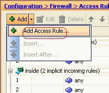
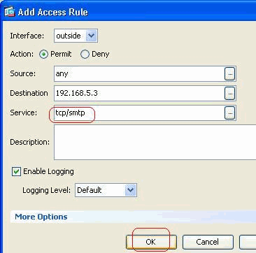
Create the access rule to permit the smtp traffic to the 192.168.5.3 server.
-
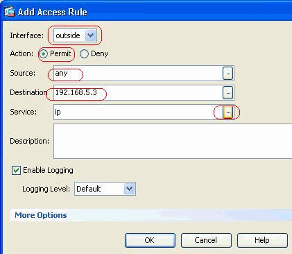
Define the source and destination of the access rule, and the interface this rule binds with. Also, define the Action as Permit.
-
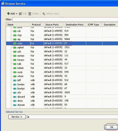
Choose SMTP as the port, then click OK.
-
Click OK to complete configuring the access rule.
-
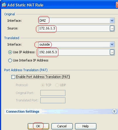
Configure the static NAT in order to translate the 172.16.1.3 to 192.168.5.3
-
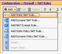
Go to Configuration > Firewall > NAT Rules > Add Static NAT Rule in order to add a static NAT entry.
-
Select the Original Source and Translated IP address along with their associated interfaces, then click OK to finish configuring the Static NAT rule.
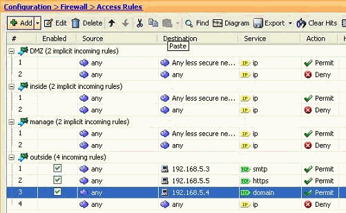
This image depicts all three static rules which are listed in the Examples section:

This image depicts all three access rules which are listed in the Examples section:
-
Verify
You can verify with certain show commands, as shown:
-
show xlate—display current translation information
-
show access-list—display hit counters for access policies
-
show logging—display the logs in the buffer.
The Output Interpreter Tool (registered customers only) (OIT) supports certain show commands. Use the OIT to view an analysis of show command output.
Troubleshoot
There is currently no specific troubleshooting information available for this configuration.
Related Information
- PIX/ASA 7.x: Enable/Disable Communication Between Interfaces
- PIX 7.0 and Adaptive Security Appliance Port Redirection(Forwarding) with nat, global, static, conduit, and access-list Commands
- Using nat, global, static, conduit, and access-list Commands and Port Redirection (Forwarding) on PIX
- PIX/ASA 7.x: Enable FTP/TFTP Services Configuration Example
- PIX/ASA 7.x: Enable VoIP (SIP,MGCP,H323,SCCP) Services Configuration Example
- PIX/ASA 7.x: Mail Server Access on the DMZ Configuration Example
- Technical Support & Documentation - Cisco Systems
Revision History
| Revision | Publish Date | Comments |
|---|---|---|
1.0 |
15-Feb-2011 |
Initial Release |
Contact Cisco
- Open a Support Case

- (Requires a Cisco Service Contract)


 Feedback