PIX/ASA and VPN Client for Public Internet VPN on a Stick Configuration Example
Available Languages
Contents
Introduction
This document describes how to set up a ASA Security Appliance 7.2 and later to perform IPsec on a stick. This setup applies to a specific case where the ASA does not allow split tunneling, and users connect directly to the ASA before they are permitted to go to the Internet.
Note: In PIX/ASA version 7.2 and later, the intra-interface keyword allows all traffic to enter and exit the same interface, and not just IPsec traffic.
Refer to Router and VPN Client for Public Internet on a Stick Configuration Example to complete a similar configuration on a central site router.
Refer to PIX/ASA 7.x Enhanced Spoke-to-Client VPN with TACACS+ Authentication Configuration Example in order to learn more about the scenario where the hub PIX redirects the traffic from the VPN Client to the spoke PIX.
Note: In order to avoid an overlap of IP addresses in the network, assign a completely different pool of IP addresses to the VPN Client (for example, 10.x.x.x , 172.16.x.x, and 192.168.x.x). This IP addressing scheme is helpful in order to troubleshoot your network.
Prerequisites
Requirements
Ensure that you meet these requirements before you attempt this configuration:
-
The hub PIX/ASA Security Appliance needs to run version 7.2 or later
-
Cisco VPN Client version 5.x
Components Used
The information in this document is based on the PIX or ASA security appliance version 8.0.2 and Cisco VPN Client version 5.0.
The information in this document was created from the devices in a specific lab environment. All of the devices used in this document started with a cleared (default) configuration. If your network is live, make sure that you understand the potential impact of any command.
Related Products
This configuration can also be used with Cisco PIX Security Appliance version 7.2 and later.
Conventions
Refer to the Cisco Technical Tips Conventions for more information on document conventions.
Background Information
Hairpinning or U-turn
This feature is useful for VPN traffic that enters an interface but is then routed out of that same interface. For example, if you have a hub-and-spoke VPN network, where the security appliance is the hub, and the remote VPN networks are spokes, in order for one spoke to communicate with another spoke, traffic must go into the security appliance and then out again to the other spoke.
Use the same-security-traffic command to allow traffic to enter and exit the same interface.
securityappliance(config)#
same-security-traffic permit intra-interface
Note: Hairpinning or U-turn is applicable for VPN Client to VPN Client communication, as well.
Configurations
In this section, you are presented with the information to configure the features described in this document.
Note: Use the Command Lookup Tool (registered customers only) to obtain more information on the commands used in this section.
Network Diagram
This document uses this network setup:
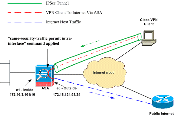
CLI Configuration of PIX/ASA
| Run Configuration on PIX/ASA |
|---|
PIX Version 8.0(2) names ! interface Ethernet0 nameif outside security-level 0 ip address 172.18.124.98 255.255.255.0 ! interface Ethernet1 nameif inside security-level 100 ip address 172.16.3.101 255.255.255.0 ! interface Ethernet2 shutdown no nameif no security-level no ip address ! interface Ethernet3 shutdown no nameif no security-level no ip address ! interface Ethernet4 shutdown no nameif no security-level no ip address ! interface Ethernet5 shutdown no nameif no security-level no ip address ! enable password 8Ry2YjIyt7RRXU24 encrypted passwd 2KFQnbNIdI.2KYOU encrypted hostname pixfirewall ftp mode passive !--- Command that permits IPsec traffic to enter and exit the same interface. same-security-traffic permit intra-interface access-list 100 extended permit icmp any any echo-reply pager lines 24 logging enable logging buffered debugging mtu outside 1500 mtu inside 1500 ip local pool vpnpool 192.168.10.1-192.168.10.254 mask 255.255.255.0 no failover monitor-interface outside monitor-interface inside icmp permit any outside no asdm history enable arp timeout 14400 nat-control !--- The address pool for the VPN Clients. !--- The global address for Internet access used by VPN Clients. !--- Note: Uses an RFC 1918 range for lab setup. !--- Apply an address from your public range provided by your ISP. global (outside) 1 172.18.124.166 !--- The NAT statement to define what to encrypt (the addresses from the vpn-pool). nat (outside) 1 192.168.10.0 255.255.255.0 nat (inside) 1 0.0.0.0 0.0.0.0 static (inside,outside) 172.16.3.102 172.16.3.102 netmask 255.255.255.255 access-group 100 in interface outside route outside 0.0.0.0 0.0.0.0 172.18.124.98 1 timeout xlate 3:00:00 timeout conn 1:00:00 half-closed 0:10:00 udp 0:02:00 icmp 0:00:02 timeout sunrpc 0:10:00 h323 0:05:00 h225 1:00:00 mgcp 0:05:00 timeout mgcp-pat 0:05:00 sip 0:30:00 sip_media 0:02:00 timeout uauth 0:05:00 absolute !--- The configuration of group-policy for VPN Clients. group-policy clientgroup internal group-policy clientgroup attributes vpn-idle-timeout 20 !--- Forces VPN Clients over the tunnel for Internet access. split-tunnel-policy tunnelall no snmp-server location no snmp-server contact snmp-server enable traps snmp !--- Configuration of IPsec Phase 2. crypto ipsec transform-set myset esp-3des esp-sha-hmac !--- Crypto map configuration for VPN Clients that connect to this PIX. crypto dynamic-map rtpdynmap 20 set transform-set myset !--- Binds the dynamic map to the crypto map process. crypto map mymap 20 ipsec-isakmp dynamic rtpdynmap !--- Crypto map applied to the outside interface. crypto map mymap interface outside !--- Enable ISAKMP on the outside interface. isakmp identity address isakmp enable outside !--- Configuration of ISAKMP policy. isakmp policy 10 authentication pre-share isakmp policy 10 encryption 3des isakmp policy 10 hash sha isakmp policy 10 group 2 isakmp policy 10 lifetime 86400 isakmp policy 65535 authentication pre-share isakmp policy 65535 encryption 3des isakmp policy 65535 hash sha isakmp policy 65535 group 2 isakmp policy 65535 lifetime 86400 telnet timeout 5 ssh timeout 5 console timeout 0 !--- Configuration of tunnel-group with group information for VPN Clients. tunnel-group rtptacvpn type ipsec-ra !--- Configuration of group parameters for the VPN Clients. tunnel-group rtptacvpn general-attributes address-pool vpnpool !--- Disable user authentication. authentication-server-group none !--- Bind group-policy parameters to the tunnel-group for VPN Clients. default-group-policy clientgroup tunnel-group rtptacvpn ipsec-attributes pre-shared-key * ! class-map inspection_default match default-inspection-traffic ! ! policy-map global_policy class inspection_default inspect dns maximum-length 512 inspect ftp inspect h323 h225 inspect h323 ras inspect netbios inspect rsh inspect rtsp inspect skinny inspect esmtp inspect sqlnet inspect sunrpc inspect tftp inspect sip inspect xdmcp ! service-policy global_policy global Cryptochecksum:1a1ad58226e700404e1053159f0c5fb0 : end |
Configure the ASA/PIX with ASDM
Complete these steps in order to configure the Cisco ASA as a remote VPN server with ASDM:
-
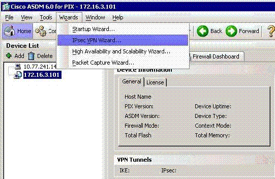
Choose Wizards > IPsec VPN Wizard from the Home window.
-
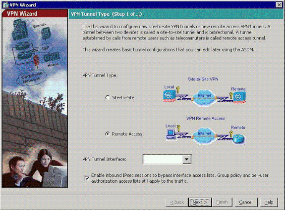
Choose the Remote Access VPN tunnel type, and ensure that the VPN Tunnel Interface is set as desired.
-
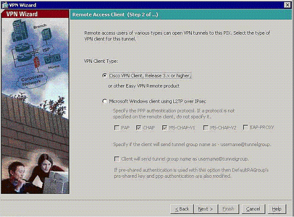
The only VPN Client Type available is already chosen. Click Next.
-
Enter a name for the Tunnel Group Name. Supply the authentication information to use.
Pre-shared Key is chosen in this example.
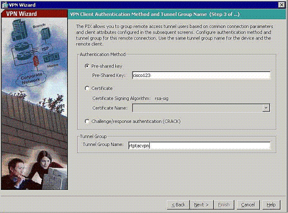
Note: There is not a way to hide/encrypt the pre-shared key on the ASDM. The reason is that the ASDM must only be used by people who configure the ASA or by people who assist the customer with this configuration.
-
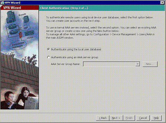
Choose whether you want remote users to be authenticated to the local user database or to an external AAA server group.
Note: You add users to the local user database in step 6.
Note: Refer to PIX/ASA 7.x Authentication and Authorization Server Groups for VPN Users via ASDM Configuration Example for information on how to configure an external AAA server group through ASDM.
-
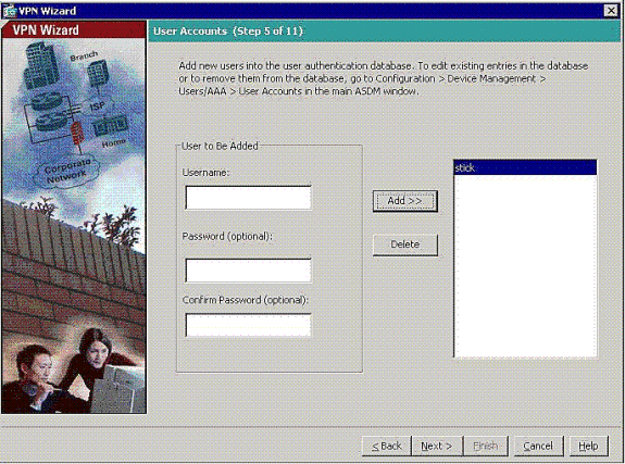
Add users to the local database, if necessary.
Note: Do not remove current users from this window. Choose Configuration > Device Administration > Administration > User Accounts in the main ASDM window to edit existent entries in the database or to remove them from the database.
-
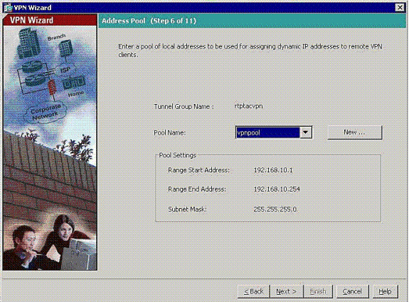
Define a pool of local addresses to be dynamically assigned to remote VPN Clients when they connect.
-
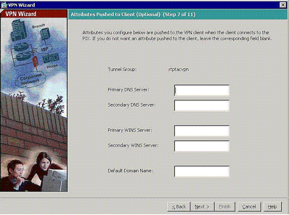
Optional: Specify the DNS and WINS server information and a Default Domain Name to be pushed to remote VPN Clients.
-
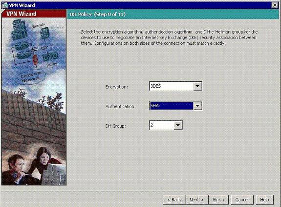
Specify the parameters for IKE, also known as IKE Phase 1.
Configurations on both sides of the tunnel must match exactly, but the Cisco VPN Client automatically chooses the proper configuration for itself. No IKE configuration is necessary on the client PC.
-
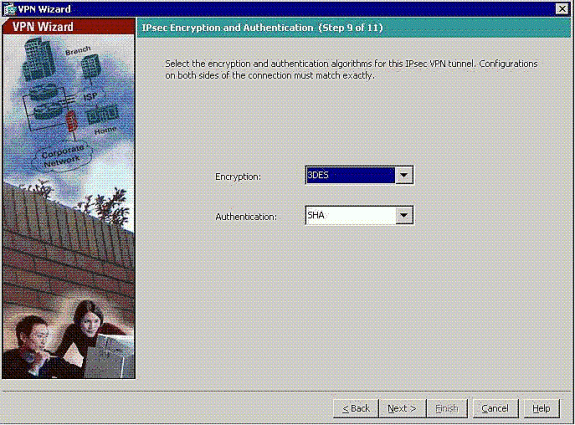
Specify the parameters for IPSec, also known as IKE Phase 2.
Configurations on both sides of the tunnel must match exactly, but the Cisco VPN Client automatically chooses the proper configuration for itself. No IKE configuration is necessary on the client PC.
-
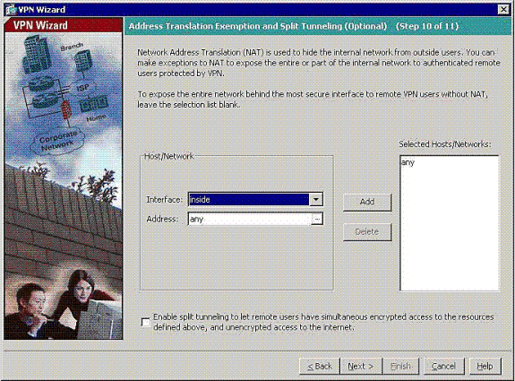
Specify which, if any, internal hosts or networks can be exposed to remote VPN users.
If you leave this list empty, it allows remote VPN users to access the entire inside network of the ASA.
You can also enable split tunneling on this window. Split tunneling encrypts traffic to the resources defined earlier in this procedure and provides unencrypted access to the Internet at large by not tunneling that traffic. If split tunneling is not enabled, all traffic from remote VPN users is tunneled to the ASA. This can become very bandwidth and processor intensive, based on your configuration.
-
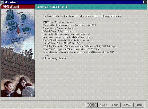
This window shows a summary of the actions that you have taken. Click Finish if you are satisfied with your configuration.
-
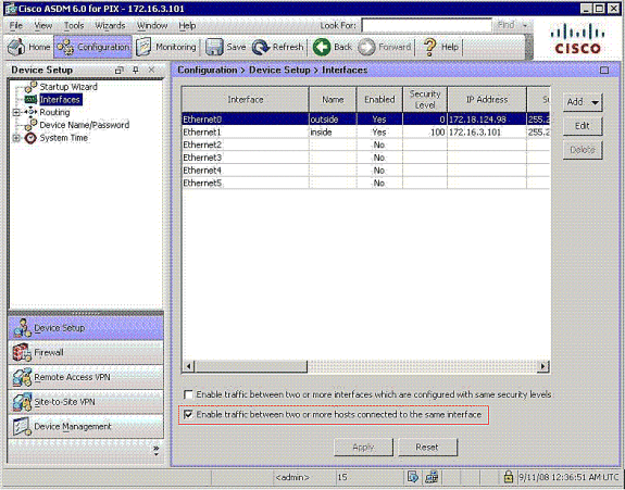
Configure the command same-security-traffic to enable traffic between two or more hosts connected to same interface when you click the checkbox as shown:
-
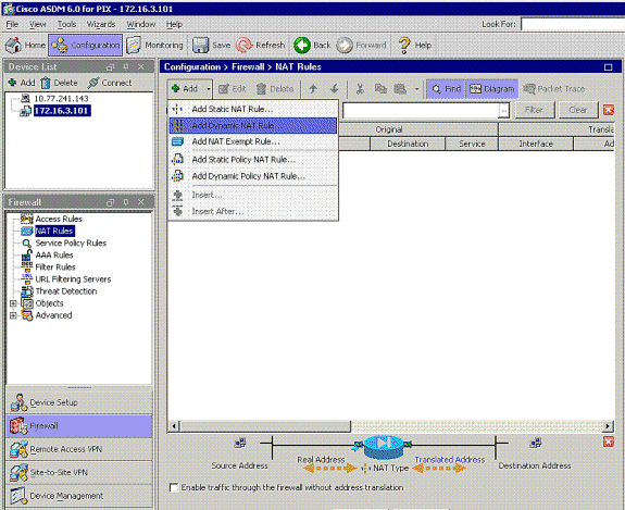
Choose Configuration > Firewall >NAT Rules, and click Add Dynamic NAT Rule in order to create this dynamic translation with the use of ASDM.
-
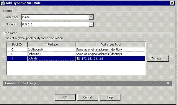
Choose inside as the source interface, and enter the addresses you want to NAT. For Translate Address on Interface, choose outside and click OK.
-
Choose outside as the source interface, and enter the addresses you want to NAT. For Translate Address on Interface, choose outside and click OK.
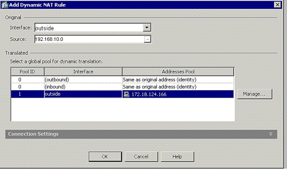
-
The translation appears in the Translation Rules at Configuration > Firewall >NAT Rules.
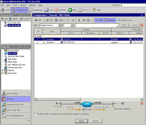
Note 1: The sysopt connection permit-vpn command needs to be configured. The show running-config sysopt command verifies if it is configured.
Note 2: Add this output for the optional UDP transport:
group-policy clientgroup attributes
vpn-idle-timeout 20

ipsec-udp enable
ipsec-udp-port 10000

split-tunnel-policy tunnelspecified
split-tunnel-network-list value splittunnel
Note 3: Configure this command in the global configuration of the PIX appliance in order for VPN Clients to connect via IPsec over TCP:
isakmp ipsec-over-tcp port 10000
Note: Refer to the Hair-Pinning on Cisco ASA ![]() video for more information on different scenarios where hair-pinning can be used.
video for more information on different scenarios where hair-pinning can be used.
VPN Client Configuration
Complete these steps to configure the VPN Client:
-
Choose New.

-
Enter the PIX outside interface ip address and tunnel-group name along with the password for authentication.
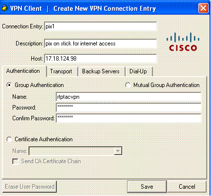
-
(Optional) Click Enable Transparent Tunneling under the Transport tab. (This is optional and requires the additional PIX/ASA configuration mentioned in note 2.)
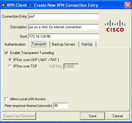
-
Save the profile.
Verify
Use this section to confirm that your configuration works properly.
The Output Interpreter Tool (registered customers only) (OIT) supports certain show commands. Use the OIT to view an analysis of show command output.
-
show crypto isakmp sa —Displays all current IKE security associations (SAs) at a peer.
-
show crypto ipsec sa —Displays all current SAs. Look for encrypt and decrypt packets on the SA that define the VPN Client traffic.
Attempt to ping or browse to a public IP address from the client (for example, www.cisco.com).
Note: The inside interface of the PIX cannot be pinged for the formation of a tunnel unless the management-access command is configured in global confirguration mode.
PIX1(config)#management-access inside
PIX1(config)#
show management-access

management-access inside
VPN Client Verification
Complete these steps in order to verify the VPN Client.
-
Right-click on the VPN Client lock icon present at the system tray after a successful connection and choose the option for statistics to view encrypts and decrypts.
-
Click on the Route Details tab in order to verify the no split-tunnel list passed down from the appliance.
Troubleshoot
Note: For more information on how to troubleshoot VPN issues, refer to VPN Troubleshooting Solutions .
Related Information
- Enhanced Spoke-to-Client VPN Configuration Example for PIX Security Appliance Version 7.0
- Cisco VPN Client
- IPsec Negotiation/IKE Protocols
- Cisco PIX Firewall Software
- Cisco Secure PIX Firewall Command References
- Security Product Field Notices (including PIX)
- Hair-Pinning on Cisco ASA

- Requests for Comments (RFCs)

- Technical Support & Documentation - Cisco Systems
Revision History
| Revision | Publish Date | Comments |
|---|---|---|
1.0 |
25-Oct-2005 |
Initial Release |
Contact Cisco
- Open a Support Case

- (Requires a Cisco Service Contract)


 Feedback