PIX/ASA 7.x and later: Connecting Multiple Internal Networks with Internet Configuration Example
Available Languages
Contents
Introduction
This document provides a sample configuration for PIX/ASA Security Appliance version 7.x and later with multiple internal networks that connect to the Internet (or an external network) using the command line interface (CLI) or Adaptive Security Device Manager (ASDM) 5.x and later.
Refer to Establish and Troubleshoot Connectivity through the Cisco Security Appliance for information on how to establish and troubleshoot connectivity through PIX/ASA.
Refer to Using nat, global, static, conduit, and access-list Commands and Port Redirection(Forwarding) on PIX for information about common PIX commands.
Note: Some options in other ASDM versions can appear different from the options in ASDM 5.1. Refer to the ASDM documentation for more information.
Prerequisites
Requirements
When you add more than one internal network behind a PIX Firewall, keep these points in mind:
-
The PIX does not support secondary addressing.
-
A router has to be used behind the PIX in order to achieve routing between the existing network and the newly added network.
-
The default gateway of all the hosts needs to point to the inside router.
-
Add a default route on the inside router that points to the PIX.
-
Clear the Address Resolution Protocol (ARP) cache on the inside router.
Refer to Allowing HTTPS Access for ASDM in order to allow the device to be configured by the ASDM.
Components Used
The information in this document is based on these software and hardware versions:
-
PIX Security Appliance 515E with software version 7.1
-
ASDM 5.1
-
Cisco routers with Cisco IOS® Software Release 12.3(7)T
Note: This document has been recertified with PIX/ASA software version 8.x and Cisco IOS Software Release 12.4.
The information in this document was created from the devices in a specific lab environment. All of the devices used in this document started with a cleared (default) configuration. If your network is live, make sure that you understand the potential impact of any command.
Related Products
This configuration can also be used with Cisco ASA Security Appliance version 7.x and later.
Conventions
Refer to the Cisco Technical Tips Conventions for more information on document conventions.
Configure
In this section, you are presented with the information to configure the features described in this document.
Note: Use the Command Lookup Tool (registered customers only) to obtain more information on the commands used in this section.
The IP addressing schemes used in this configuration are not legally routable on the Internet. They are RFC 1918 addresses which have been used in a lab environment.
Background Information
In this scenario, there are three internal networks (10.1.1.0/24, 10.2.1.0/24 and 10.3.1.0/24) to be connected to the Internet (or an External network) through PIX. The internal networks are connected to the inside interface of PIX. The Internet connectivity is through a router which is connected to the outside interface of the PIX. The PIX has the IP address 172.16.1.1/24.
The static routes are used to route the packets from the internal networks to the Internet and vice versa. Instead of using the static routes, you can also use a dynamic routing protocol such as Routing Information Protocol (RIP) or Open Shortest Path First (OSPF).
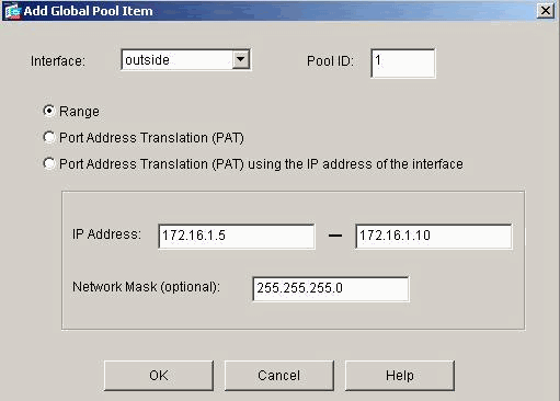
The internal hosts communicate with the Internet by translating the internal networks on PIX using dynamic NAT (pool of IP addresses - 172.16.1.5 to 172.16.1.10 ). If the pool of IP addresses is exhausted, the PIX will PAT (using IP address 172.16.1.4) the internal hosts to reach the Internet.
Refer to PIX/ASA 7.x NAT and PAT Statements for more information on NAT/PAT.
Note: If the static NAT uses the outside IP (global_IP) address to translate, then this might cause a translation. Therefore, use the keyword interface instead of the IP address in the static translation.
Network Diagram
This document uses this network setup:
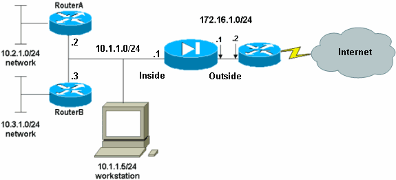
The default gateway of the hosts on the 10.1.1.0 network points to RouterA. A default route on RouterB is added that points to RouterA. RouterA has a default route that points to the PIX inside interface.
Configurations
This document uses these configurations:
| RouterA Configuration |
|---|
RouterA#show running-config Building configuration... Current configuration : 1151 bytes ! version 12.4 service config service timestamps debug uptime service timestamps log uptime no service password-encryption ! hostname RouterA ! interface Ethernet2/0 ip address 10.2.1.1 255.255.255.0 half-duplex ! interface Ethernet2/1 ip address 10.1.1.2 255.255.255.0 half-duplex ! ip classless ip route 0.0.0.0 0.0.0.0 10.1.1.1 ip route 10.3.1.0 255.255.255.0 10.1.1.3 ! ! line con 0 line aux 0 line vty 0 4 ! end RouterA# |
| RouterB Configuration |
|---|
RouterB#show running-config Building configuration... Current configuration : 1132 bytes ! version 12.4 service config service timestamps debug datetime msec service timestamps log datetime msec no service password-encryption ! hostname RouterB ! interface FastEthernet0/0 ip address 10.1.1.3 255.255.255.0 speed auto ! interface Ethernet1/0 ip address 10.3.1.1 255.255.255.0 half-duplex ! ip classless ip route 0.0.0.0 0.0.0.0 10.1.1.2 ! control-plane ! ! line con 0 line aux 0 line vty 0 4 ! end RouterB# |
If you want to use the ASDM for the configuration of the PIX Security Appliance, but have not bootstrapped the device, complete these steps:
-
Console into the PIX.
-
From a cleared configuration, use the interactive prompts in order to enable ASDM for the management of the PIX from workstation 10.1.1.5.
| PIX Security Appliance 7.1 Configuration |
|---|
Pre-configure Firewall now through interactive prompts [yes]? yes
Firewall Mode [Routed]:
Enable password [<use current password>]: cisco
Allow password recovery [yes]?
Clock (UTC):
  Year [2005]:
  Month [Mar]:
  Day [15]:
  Time [05:40:35]: 14:45:00
Inside IP address: 10.1.1.1
Inside network mask: 255.255.255.0
Host name: OZ-PIX
Domain name: cisco.com
IP address of host running Device Manager: 10.1.1.5

The following configuration will be used:
         Enable password: cisco
         Allow password recovery: yes
         Clock (UTC): 14:45:00 Mar 15 2005
         Firewall Mode: Routed
         Inside IP address: 10.1.1.1
         Inside network mask: 255.255.255.0
         Host name: OZ-PIX
         Domain name: cisco.com
         IP address of host running Device Manager: 10.1.1.5

Use this configuration and write to flash? yes
         INFO: Security level for "inside" set to 100 by default.
         Cryptochecksum: a0bff9bb aa3d815f c9fd269a 3f67fef5

965 bytes copied in 0.880 secs
         INFO: converting 'fixup protocol dns maximum-length 512' to MPF commands
         INFO: converting 'fixup protocol ftp 21' to MPF commands
         INFO: converting 'fixup protocol h323_h225 1720' to MPF commands
         INFO: converting 'fixup protocol h323_ras 1718-1719' to MPF commands
         INFO: converting 'fixup protocol netbios 137-138' to MPF commands
         INFO: converting 'fixup protocol rsh 514' to MPF commands
         INFO: converting 'fixup protocol rtsp 554' to MPF commands
         INFO: converting 'fixup protocol sip 5060' to MPF commands
         INFO: converting 'fixup protocol skinny 2000' to MPF commands
         INFO: converting 'fixup protocol smtp 25' to MPF commands
         INFO: converting 'fixup protocol sqlnet 1521' to MPF commands
         INFO: converting 'fixup protocol sunrpc_udp 111' to MPF commands
         INFO: converting 'fixup protocol tftp 69' to MPF commands
         INFO: converting 'fixup protocol sip udp 5060' to MPF commands
         INFO: converting 'fixup protocol xdmcp 177' to MPF commands

Type help or '?' for a list of available commands.
OZ-PIX> |
PIX Configuration using ASDM
Complete these steps in order to configure via the ASDM GUI:
-
From workstation 10.1.1.5, open a web browser to use ADSM (in this example, https://10.1.1.1).
-
Click yes on the certificate prompts.
-
Log in with the enable password, as previously configured.
-
If this is the first time ASDM is run on the PC, you are prompted to use ASDM Launcher or ASDM as a Java App. In this example, the ASDM Launcher is selected and installed.
-
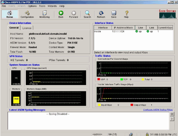
Go to the ASDM Home window and click Configuration.
-
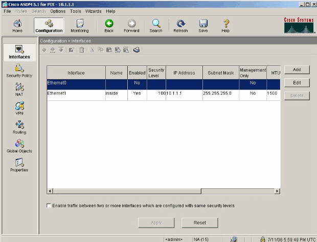
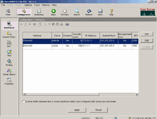
Choose Interface > Edit in order to configure the outside interface.
-
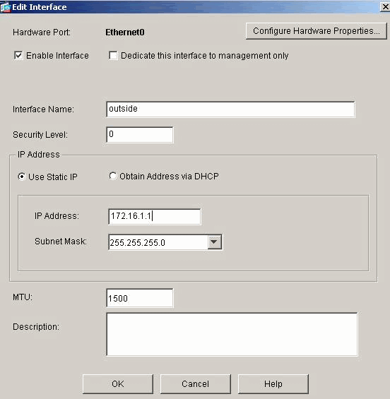
Enter the interface details and click OK when you are done.
-
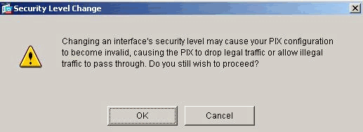
Click OK on the Security Level Change dialog box.
-
Click Apply to accept the interface configuration. The configuration also gets pushed onto the PIX.
-
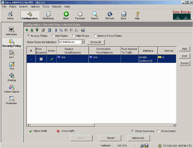
Choose Security Policy on the Features tab in order to review the security policy rule used. In this example, the default inside rule is used.
-
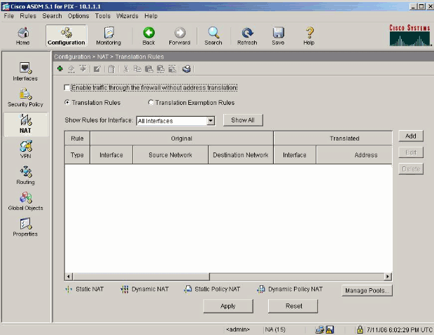
In this example, NAT is used. Uncheck the Enable traffic through the firewall without address translation check box and click Add in order to configure the NAT rule.
-
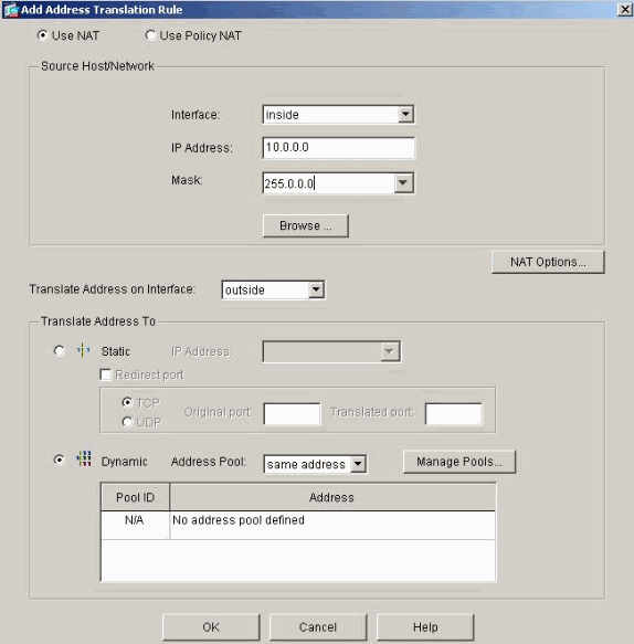
Configure the Source Network. In this example, 10.0.0.0 is used for the IP address, and 255.0.0.0 is used for the mask.
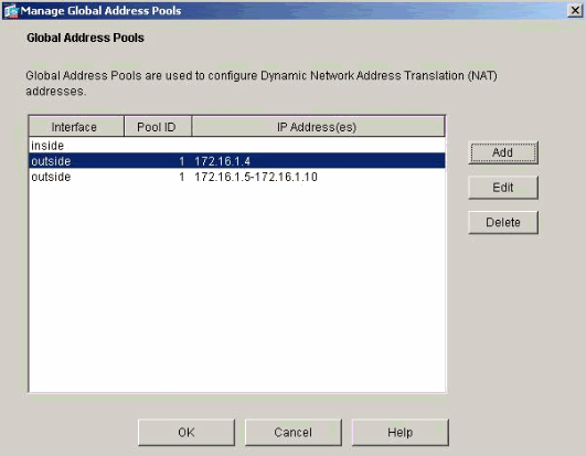
Click Manage Pools in order to define the NAT pool addresses.
-
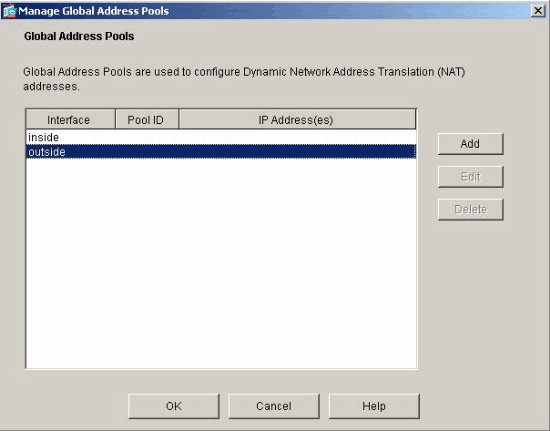
Select the outside interface and click Add.
-
In this example, a Range and PAT address pool are configured. Configure the range NAT pool address and click OK.
-
Select the outside interface in step 13 in order to configure the PAT address. Click OK
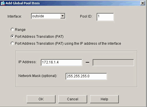
Click OK in order to continue.
-
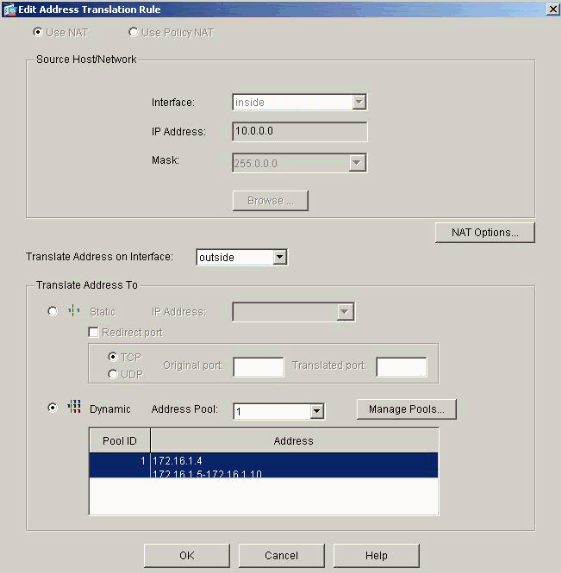
On the Edit Address Translation Rule window, select the Pool ID to be used by the source network configured. Click OK.
-
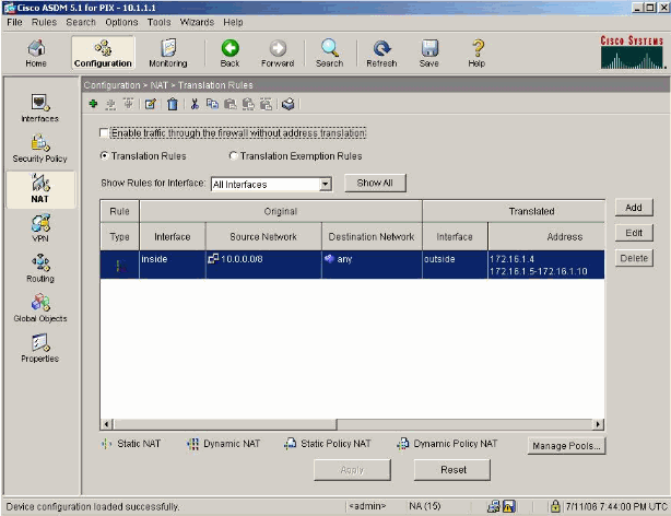
Click Apply in order to push the configured NAT rule to the PIX.
-
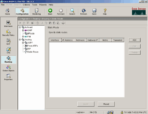
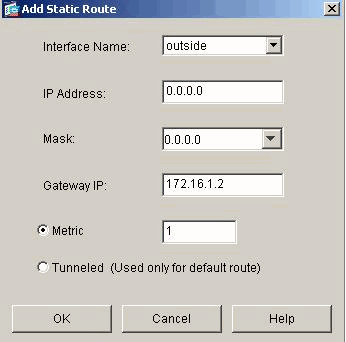
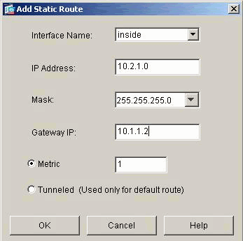
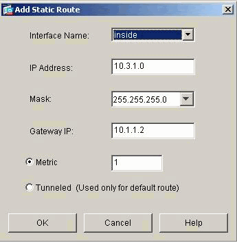
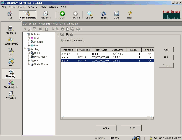
In this example, static routes are used. Click Routing, choose Static Route and click Add.
-
Configure the default gateway and click OK.
-
Click Add and add the routes to the inside networks.
-
Confirm that the correct routes are configured and click Apply.
PIX Configuration using CLI
Configuration via the ASDM GUI is now complete.
You can see this configuration via the CLI:
| PIX Security Appliance CLI |
|---|
pixfirewall(config)#write terminal PIX Version 7.0(0)102 names ! interface Ethernet0 nameif outside security-level 0 ip address 172.16.1.1 255.255.255.0 ! interface Ethernet1 nameif inside security-level 100 ip address 10.1.1.1 255.255.255.0 !--- Assign name and IP address to the interfaces enable password 2KFQnbNIdI.2KYOU encrypted passwd 2KFQnbNIdI.2KYOU encrypted asdm image flash:/asdmfile.50073 no asdm history enable arp timeout 14400 nat-control !--- Enforce a strict NAT for all the traffic through the Security appliance global (outside) 1 172.16.1.5-172.16.1.10 netmask 255.255.255.0 !--- Define a pool of global addresses 172.16.1.5 to 172.16.1.10 with !--- NAT ID 1 to be used for NAT global (outside) 1 172.16.1.4 netmask 255.255.255.0 !--- Define a single IP address 172.16.1.4 with NAT ID 1 to be used for PAT nat (inside) 1 10.0.0.0 255.0.0.0 !--- Define the inside networks with same NAT ID 1 used in the global command for NAT route inside 10.3.1.0 255.255.255.0 10.1.1.3 1 route inside 10.2.1.0 255.255.255.0 10.1.1.2 1 !--- Configure static routes for routing the packets towards the internal network route outside 0.0.0.0 0.0.0.0 172.16.1.2 1 !--- Configure static route for routing the packets towards the Internet (or External network) timeout xlate 3:00:00 timeout conn 1:00:00 half-closed 0:10:00 udp 0:02:00 icmp 0:00:02 sunrpc 0:10:00 h323 0:05:00 h225 1:00:00 mgcp 0:05:00 mgcp-pat 0:05:00 sip 0:30:00 sip_media 0:02:00 timeout uauth 0:05:00 absolute http server enable !--- Enable the HTTP server on PIX for ASDM access http 10.1.1.5 255.255.255.255 inside !--- Enable HTTP access from host 10.1.1.5 to configure PIX using ASDM (GUI) ! !--- Output suppressed ! ! Cryptochecksum:a0bff9bbaa3d815fc9fd269a3f67fef5 : end |
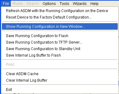
Choose File > Show Running Configuration in New Window in order to view the CLI configuration in ASDM.
Verify
There is currently no verification procedure available for this configuration.
Troubleshoot
Troubleshooting Commands
The Output Interpreter Tool (registered customers only) (OIT) supports certain show commands. Use the OIT to view an analysis of show command output.
Note: Refer to Important Information on Debug Commands before you use debug commands.
-
debug icmp trace—Shows whether ICMP requests from the hosts reach the PIX. In order to run this debug, you need to add the access-list command to permit ICMP in your configuration.
-
logging buffer debugging—Shows connections that are established and denied to hosts that go through the PIX. The information is stored in the PIX log buffer and you can see the output with the show log command.
Troubleshooting Procedure
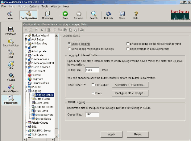
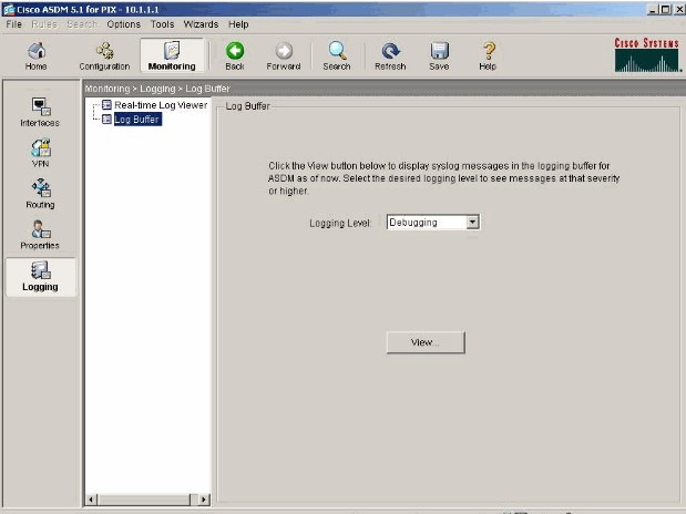
ASDM can be used to enable logging, and also to view the logs:
-
Choose Configuration > Properties > Logging > Logging Setup, check Enable Logging, and click Apply.
-
Choose Monitoring > Logging > Log Buffer > Logging Level and choose Logging Buffer from the drop-down list. Click View.
-
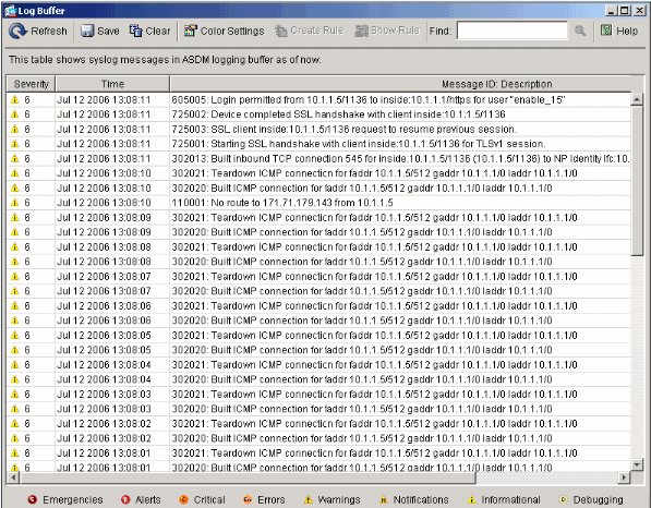
Here is an example of the Log Buffer:
Unable to Access Websites by Name
In certain scenarios, the internal networks cannot access the internet websites by using name (works with IP address) in the web browser. This issue is common and usually occurs if the DNS server is not defined, especially in cases where PIX/ASA is the DHCP server. Also, this can occur in cases if the PIX/ASA is unable to push the DNS server or if the DNS server is not reachable.
Related Information
- Cisco PIX 500 Series Security Appliances
- Cisco ASA 5500 Series Adaptive Security Appliances
- Cisco Secure PIX Firewall Command References
- Cisco Adaptive Security Device Manager
- Cisco Adaptive Security Device Manager (ASDM) Troubleshoot and Alerts
- Requests for Comments (RFCs)

- Technical Support & Documentation - Cisco Systems
Revision History
| Revision | Publish Date | Comments |
|---|---|---|
1.0 |
27-Jan-2005 |
Initial Release |
Contact Cisco
- Open a Support Case

- (Requires a Cisco Service Contract)


 Feedback