Introduction
This document describes how to work around a scenario where the Administrator is not able to authenticate to a Standby Cisco Adaptive Security Appliance (ASA) in a Failover Pair due to the fact that the Authentication, Authorization, and Accounting (AAA) server is located on a remote location through a LAN-to-LAN (L2L).
Although fallback to LOCAL authentication can be used, RADIUS Authentication for both units is preferred.
Prerequisites
Requirements
Cisco recommends that you have knowledge of these topics:
- ASA Failover
- VPN
- Network Address Translation (NAT)
Components Used
This document is not restricted to specific software and hardware versions.
The information in this document was created from the devices in a specific lab environment. All of the devices used in this document started with a cleared (default) configuration. If your network is live, make sure that you understand the potential impact of any command.
Configure
Note: Use the Command Lookup Tool (registered customers only) in order to obtain more information on the commands used in this section.
Network Diagram
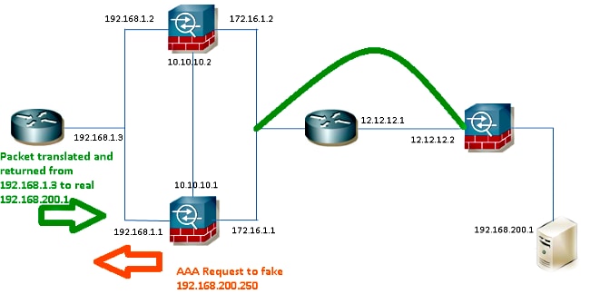
The RADIUS server is located on the outside of the Failover Pair and it is reachable through a L2L tunnel to 12.12.12.2. This is what causes the probem because the standby ASA tries to reach it through its own outside interface but there is no tunnel built on it at this point; for it to work, it should send the request to the active interface so the packet can flow across the VPN but the routes are replicated from the active unit.
One option is to use a fake IP address for the RADIUS Server on the ASAs and point it to the inside. Therefore, the source and destination IP address of this packet can be translated on an internal device.

Router1
interface FastEthernet0/0
 ip address 192.168.1.3 255.255.255.0
 no ip redirects
 no ip unreachables
 ip nat enable
 duplex auto
 speed auto

ip access-list extended NAT
 permit ip 192.168.1.0 0.0.0.255 host 192.168.200.250

ip nat source list NAT interface FastEthernet0/0 overload
ip nat source static 192.168.200.1 192.168.200.250

ip route 0.0.0.0 0.0.0.0 192.168.1.1
ASAs
aaa-server RADIUS protocol radius
aaa-server RADIUS (inside) host 192.168.200.250
 timeout 3
 key *****
 authentication-port 1812
 accounting-port 1813

aaa authentication serial console LOCAL
aaa authentication ssh console RADIUS LOCAL
aaa authentication telnet console RADIUS LOCAL
aaa authentication http console RADIUS LOCAL
aaa authentication enable console RADIUS LOCAL

route outside 0.0.0.0 0.0.0.0 172.16.1.3 1
route inside 192.168.200.250 255.255.255.255 192.168.1.3 1
Note: The 192.168.200.250 IP address was used in the example, but any unused IP address works.
Verify
Use this section in order to confirm that your configuration works properly.
The Output Interpreter Tool (registered customers only) supports certain show commands. Use the Output Interpreter Tool in order to view an analysis of show command output.
Router
Router#   show ip nat nvi tra
Pro Source global      Source local       Destin  local      Destin  global
udp 192.168.1.3:1025   192.168.1.1:1025   192.168.200.250:1812 192.168.200.1:1812
--- 192.168.200.1      192.168.2.1        ---                ---
--- 192.168.200.250    192.168.200.1      ---                ---
Troubleshoot
There is currently no specific troubleshooting information available for this configuration.
