ASA/PIX: Remote VPN Server with Inbound NAT for VPN Client Traffic with CLI and ASDM Configuration Example
Available Languages
Contents
Introduction
This document describes how to configure the Cisco 5500 Series Adaptive Security Appliance (ASA) to act as a remote VPN server using the Adaptive Security Device Manager (ASDM) or CLI and NAT the Inbound VPN Client traffic. The ASDM delivers world-class security management and monitoring through an intuitive, easy-to-use Web-based management interface. Once the Cisco ASA configuration is complete, it can be verified through the Cisco VPN Client.
Prerequisites
Requirements
This document assumes that the ASA is fully operational and configured to allow the Cisco ASDM or CLI to make configuration changes. The ASA is also assumed to be configured for Outbound NAT. Refer to Allow Inside Hosts Access to Outside Networks with the use of PAT for more information on how to configure Outbound NAT.
Note: Refer to Allowing HTTPS Access for ASDM or PIX/ASA 7.x: SSH on the Inside and Outside Interface Configuration Example to allow the device to be remotely configured by the ASDM or Secure Shell (SSH).
Components Used
The information in this document is based on these software and hardware versions:
-
Cisco Adaptive Security Appliance Software version 7.x and later
-
Adaptive Security Device Manager version 5.x and later
-
Cisco VPN Client version 4.x and later
The information in this document was created from the devices in a specific lab environment. All of the devices used in this document started with a cleared (default) configuration. If your network is live, make sure that you understand the potential impact of any command.
Related Products
This configuration can also be used with Cisco PIX Security Appliance version 7.x and later.
Conventions
Refer to Cisco Technical Tips Conventions for more information on document conventions.
Background Information
Remote access configurations provide secure remote access for Cisco VPN clients, such as mobile users. A remote access VPN lets remote users securely access centralized network resources. The Cisco VPN Client complies with the IPSec protocol and is specifically designed to work with the security appliance. However, the security appliance can establish IPSec connections with many protocol-compliant clients. Refer to ASA Configuration Guides for more information on IPSec.
Groups and users are core concepts in the management of the security of VPNs and in the configuration of the security appliance. They specify attributes that determine users access to and use of the VPN. A group is a collection of users treated as a single entity. Users get their attributes from group policies. Tunnel groups identify the group policy for specific connections. If you do not assign a particular group policy to users, the default group policy for the connection applies.
A tunnel group consists of a set of records that determines tunnel connection policies. These records identify the servers to which the tunnel users are authenticated, as well as the accounting servers, if any, to which connection information is sent. They also identifiy a default group policy for the connections, and they contain protocol-specific connection parameters. Tunnel groups include a small number of attributes that pertain to the creation of the tunnel itself. Tunnel groups include a pointer to a group policy that defines user-oriented attributes.
Configurations
Configure the ASA/PIX as a Remote VPN Server with ASDM
Complete these steps in order to configure the Cisco ASA as a remote VPN server with ASDM:
-
Open your browser and enter https://<IP_Address of the interface of ASA that has been configured for ASDM Access> in order to access the ASDM on the ASA.
Make sure to authorize any warnings your browser gives you related to SSL certificate authenticity. The default username and password are both blank.
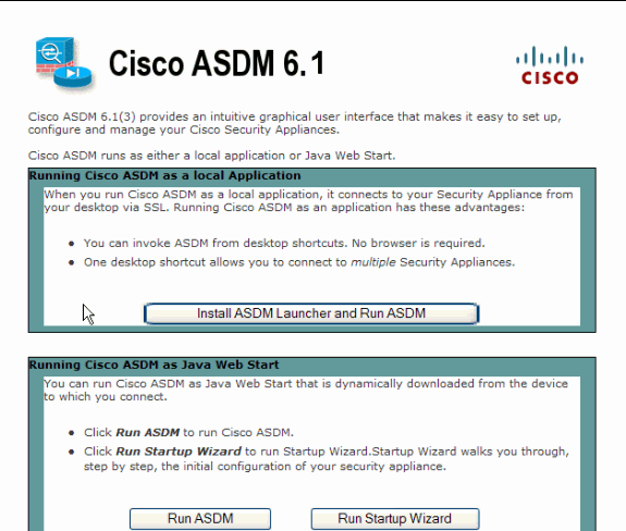
The ASA presents this window to allow the download of the ASDM application. This example loads the application onto the local computer and does not run in a Java applet.
-
Click Download ASDM Launcher and Start ASDM in order to download the installer for the ASDM application.
-
Once the ASDM Launcher downloads, complete the steps directed by the prompts in order to install the software and run the Cisco ASDM Launcher.
-
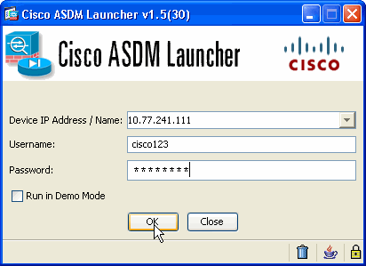
Enter the IP address for the interface you configured with the http - command, and a username and password if you specified one.
This example uses cisco123 as the username and cisco123 as the password.
-
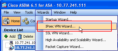
Select Wizards > IPsec VPN Wizard from the Home window.
-
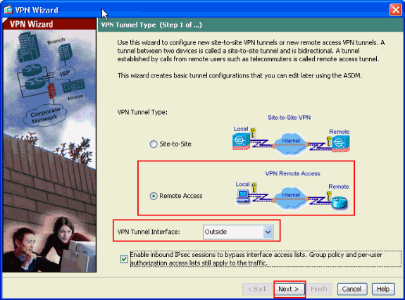
Select the Remote Access VPN tunnel type and ensure that the VPN Tunnel Interface is set as desired, and click Next as shown here.
-
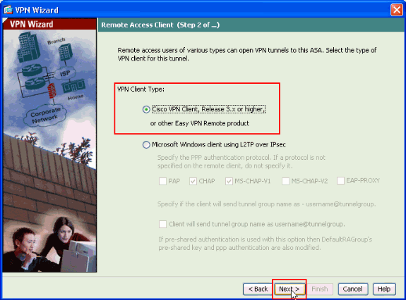
The VPN Client Type is chosen, as shown. Cisco VPN Client is chosen here. Click Next.
-
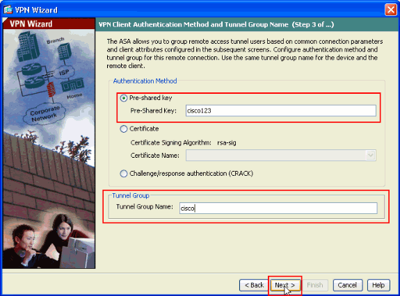
Enter a name for the Tunnel Group Name. Enter the authentication information to use, which is the pre-shared key in this example. The pre-shared key used in this example is cisco123. The Tunnel Group Name used in this example is cisco. Click Next.
-
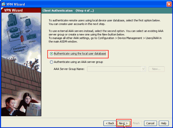
Choose whether you want remote users to be authenticated to the local user database or to an external AAA server group.
Note: You add users to the local user database in step 10.
Note: Refer to PIX/ASA 7.x Authentication and Authorization Server Groups for VPN Users via ASDM Configuration Example for information on how to configure an external AAA server group with ASDM.
-
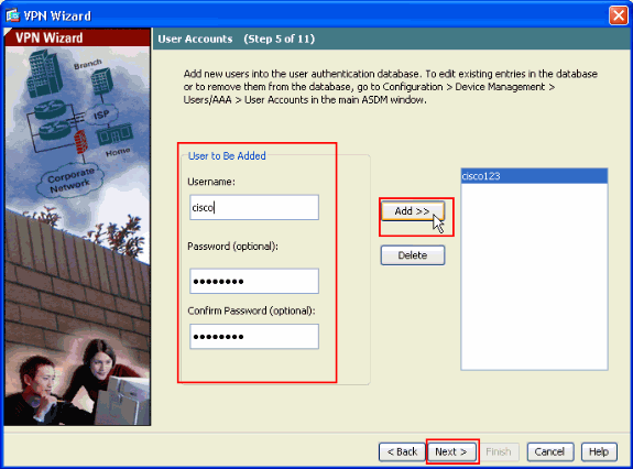
Provide a Username and optional Password and click Add in order to add new users to the user authentication database. Click Next.
Note: Do not remove existing users from this window. Select Configuration > Device Management > Users/AAA > User Accounts in the main ASDM window to edit existing entries in the database or to remove them from the database.
-
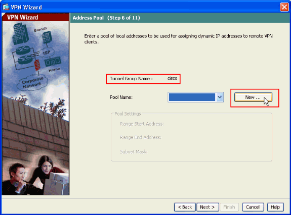
In order to define a pool of local addresses to be dynamically assigned to remote VPN Clients, click New to create a new IP Pool.
-
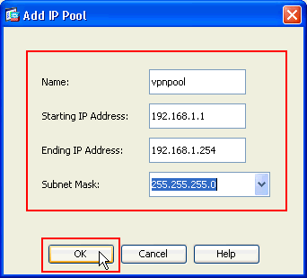
In the new window titled Add IP Pool provide this information, and click OK.
-
Name of the IP Pool
-
Starting IP Address
-
Ending IP Address
-
Subnet Mask
-
-
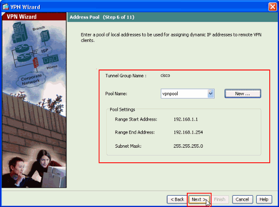
After you define the pool of local addresses to be dynamically assigned to remote VPN Clients when they connect, click Next.
-
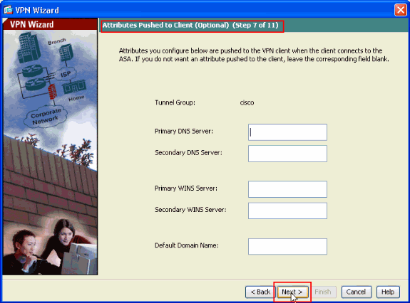
Optional: Specify the DNS and WINS server information and a Default Domain Name to be pushed to remote VPN Clients.
-
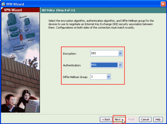
Specify the parameters for IKE, also known as IKE Phase 1.
Configurations on both sides of the tunnel must match exactly. However, the Cisco VPN Client automatically selects the proper configuration for itself. Therefore, no IKE configuration is necessary on the client PC.
-
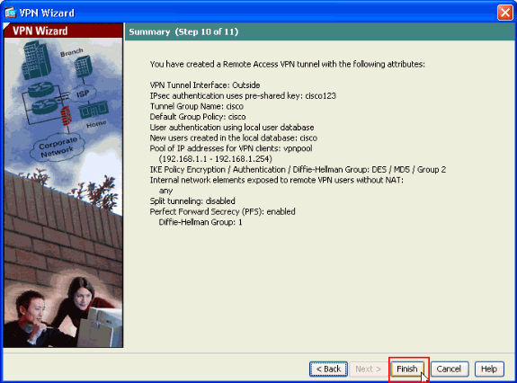
This window shows a summary of the actions that you have taken. Click Finish if you are satisfied with your configuration.
Configure the ASA/PIX to NAT Inbound VPN Client Traffic with ASDM
Complete these steps in order to configure the Cisco ASA to NAT Inbound VPN Client traffic with ASDM:
-
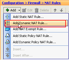
Choose Configuration > Firewall > Nat Rules, and click Add. In the drop-down list, select Add Dynamic NAT Rule.
-
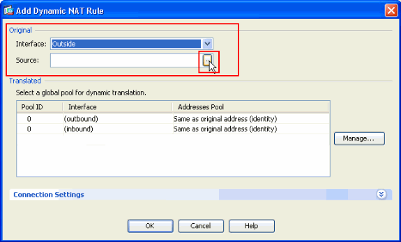
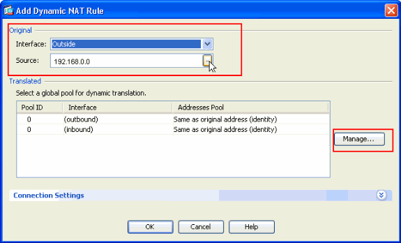
In the Add Dynamic NAT Rule window, choose Outside as the Interface, and click the browse button next to the Source box.
-
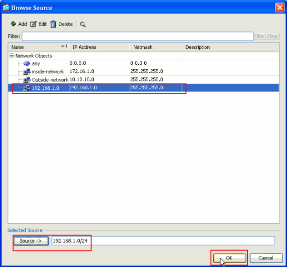
In the Browse Source window, select the proper network objects and also choose the source under the Selected Source section, and click OK. Here the 192.168.1.0 Network Object is chosen.
-
Click Manage.
-
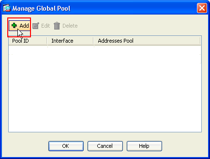
In the Manage Global Pool window, click Add.
-
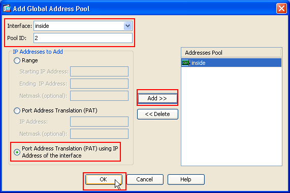
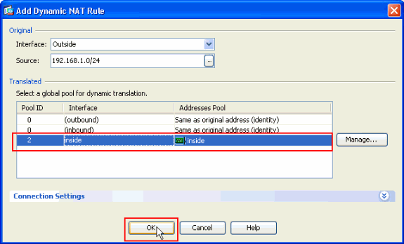
In the Add Global Address Pool window, choose Inside as the Interface and 2 as the Pool ID. Also make sure that the radio button next to PAT using IP Address of the interface is selected. Click Add>>, and then click OK.
-
Click OK after you select the global pool with the Pool ID 2 configured in the previous step.
-
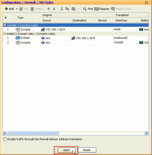
Now click Apply so that the configuration is applied to the ASA.This completes the configuration.
Configure the ASA/PIX as a Remote VPN Server and for Inbound NAT with the CLI
| Running Config on the ASA Device |
|---|
ciscoasa#show running-config : Saved ASA Version 8.0(3) ! hostname ciscoasa enable password 8Ry2YjIyt7RRXU24 encrypted names ! interface Ethernet0/0 nameif Outside security-level 0 ip address 10.10.10.2 255.255.255.0 ! interface Ethernet0/1 nameif inside security-level 100 ip address 172.16.1.2 255.255.255.0 ! ! passwd 2KFQnbNIdI.2KYOU encrypted boot system disk0:/asa803-k8.bin ftp mode passive access-list inside_nat0_outbound extended permit ip any 192.168.1.0 255.255.255 0 pager lines 24 logging enable mtu Outside 1500 mtu inside 1500 ip local pool vpnpool 192.168.1.1-192.168.1.254 mask 255.255.255.0 no failover icmp unreachable rate-limit 1 burst-size 1 asdm image disk0:/asdm-615.bin asdm history enable arp timeout 14400 nat-control global (Outside) 1 interface global (inside) 2 interface nat (Outside) 2 192.168.1.0 255.255.255.0 outside nat (inside) 0 access-list inside_nat0_outbound nat (inside) 1 0.0.0.0 0.0.0.0 route Outside 0.0.0.0 0.0.0.0 10.10.10.3 1 timeout xlate 3:00:00 timeout conn 1:00:00 half-closed 0:10:00 udp 0:02:00 icmp 0:00:02 timeout sunrpc 0:10:00 h323 0:05:00 h225 1:00:00 mgcp 0:05:00 mgcp-pat 0:05:00 timeout sip 0:30:00 sip_media 0:02:00 sip-invite 0:03:00 sip-disconnect 0:02:00 timeout uauth 0:05:00 absolute dynamic-access-policy-record DfltAccessPolicy http server enable no snmp-server location no snmp-server contact !--- Configuration for IPsec policies. !--- Enables the crypto transform configuration mode, !--- where you can specify the transform sets that are used !--- during an IPsec negotiation. crypto ipsec transform-set ESP-DES-SHA esp-des esp-sha-hmac crypto ipsec transform-set ESP-DES-MD5 esp-des esp-md5-hmac crypto dynamic-map SYSTEM_DEFAULT_CRYPTO_MAP 65535 set pfs group1 crypto dynamic-map SYSTEM_DEFAULT_CRYPTO_MAP 65535 set transform-set ESP-DES-SH ESP-DES-MD5 crypto map Outside_map 65535 ipsec-isakmp dynamic SYSTEM_DEFAULT_CRYPTO_MAP crypto map Outside_map interface Outside crypto isakmp enable Outside !--- Configuration for IKE policies. !--- Enables the IKE policy configuration (config-isakmp) !--- command mode, where you can specify the parameters that !--- are used during an IKE negotiation. Encryption and !--- Policy details are hidden as the default values are chosen. crypto isakmp policy 10 authentication pre-share encryption des hash sha group 2 lifetime 86400 crypto isakmp policy 30 authentication pre-share encryption des hash md5 group 2 lifetime 86400 telnet timeout 5 ssh timeout 60 console timeout 0 management-access inside threat-detection basic-threat threat-detection statistics access-list group-policy cisco internal group-policy cisco attributes vpn-tunnel-protocol IPSec !--- Specifies the username and password with their !--- respective privilege levels username cisco123 password ffIRPGpDSOJh9YLq encrypted privilege 15 username cisco password ffIRPGpDSOJh9YLq encrypted privilege 0 username cisco attributes vpn-group-policy cisco tunnel-group cisco type remote-access tunnel-group cisco general-attributes address-pool vpnpool default-group-policy cisco !--- Specifies the pre-shared key "cisco123" which must !--- be identical at both peers. This is a global !--- configuration mode command. tunnel-group cisco ipsec-attributes pre-shared-key * ! class-map inspection_default match default-inspection-traffic ! ! policy-map type inspect dns migrated_dns_map_1 parameters message-length maximum 512 policy-map global_policy class inspection_default inspect dns migrated_dns_map_1 inspect ftp inspect h323 h225 inspect h323 ras inspect netbios inspect rsh inspect rtsp inspect skinny inspect esmtp inspect sqlnet inspect sunrpc inspect tftp inspect sip inspect xdmcp ! service-policy global_policy global prompt hostname context Cryptochecksum:f2ad6f9d5bf23810a26f5cb464e1fdf3 : end ciscoasa# |
Verify
Attempt to connect to the Cisco ASA through the Cisco VPN Client in order to verify that the ASA is successfully configured.
-
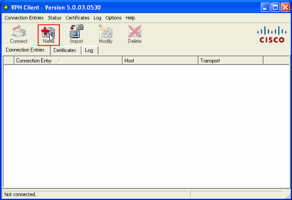
Click New.
-
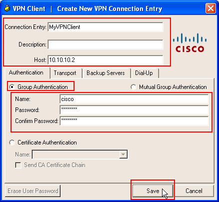
Fill in the details of your new connection.
The Host field must contain the IP address or hostname of the previously configured Cisco ASA. The Group Authentication information must correspond to that used in step 4. Click Save when you are finished.
-
Select the newly created connection, and click Connect.
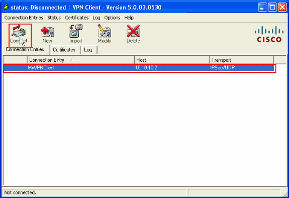
-
Enter a username and password for extended authentication. This information must match that specified in steps 5 and 6.
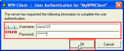
-
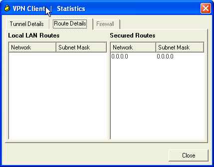
Once the connection is successfully established, choose Statistics from the Status menu in order to verify the details of the tunnel.
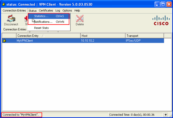
This window shows traffic and crypto information:
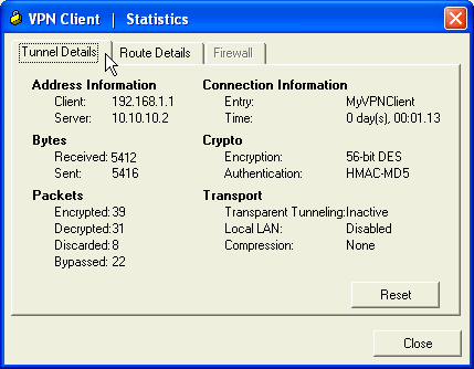
This window shows split tunneling information:
ASA/PIX Security Appliance - show Commands
-
show crypto isakmp sa—Shows all current IKE SAs at a peer.
ASA#show crypto isakmp sa Active SA: 1 Rekey SA: 0 (A tunnel will report 1 Active and 1 Rekey SA during rekey) Total IKE SA: 1 1 IKE Peer: 10.10.10.1 Type : user Role : responder Rekey : no State : AM_ACTIVE -
show crypto ipsec sa—Shows all current IPsec SAs at a peer.
ASA#show crypto ipsec sa interface: Outside Crypto map tag: SYSTEM_DEFAULT_CRYPTO_MAP, seq num: 65535, local addr: 10.10 .10.2 local ident (addr/mask/prot/port): (0.0.0.0/0.0.0.0/0/0) remote ident (addr/mask/prot/port): (192.168.1.1/255.255.255.255/0/0) current_peer: 10.10.10.1, username: cisco123 dynamic allocated peer ip: 192.168.1.1 #pkts encaps: 20, #pkts encrypt: 20, #pkts digest: 20 #pkts decaps: 74, #pkts decrypt: 74, #pkts verify: 74 #pkts compressed: 0, #pkts decompressed: 0 #pkts not compressed: 20, #pkts comp failed: 0, #pkts decomp failed: 0 #pre-frag successes: 0, #pre-frag failures: 0, #fragments created: 0 #PMTUs sent: 0, #PMTUs rcvd: 0, #decapsulated frgs needing reassembly: 0 #send errors: 0, #recv errors: 0 local crypto endpt.: 10.10.10.2, remote crypto endpt.: 10.10.10.1 path mtu 1500, ipsec overhead 58, media mtu 1500 current outbound spi: F49F954C inbound esp sas: spi: 0x3C10F9DD (1007745501) transform: esp-des esp-md5-hmac none in use settings ={RA, Tunnel, } slot: 0, conn_id: 24576, crypto-map: SYSTEM_DEFAULT_CRYPTO_MAP sa timing: remaining key lifetime (sec): 27255 IV size: 8 bytes replay detection support: Y outbound esp sas: spi: 0xF49F954C (4104099148) transform: esp-des esp-md5-hmac none in use settings ={RA, Tunnel, } slot: 0, conn_id: 24576, crypto-map: SYSTEM_DEFAULT_CRYPTO_MAP sa timing: remaining key lifetime (sec): 27255 IV size: 8 bytes replay detection support: Y -
ciscoasa(config)#debug icmp trace

!--- Inbound Nat Translation is shown below for Outside to Inside

ICMP echo request translating Outside:192.168.1.1/768 to inside:172.16.1.2/1
ICMP echo reply from inside:172.16.1.3 to Outside:172.16.1.2 ID=1 seq=7936 len=3
2

!--- Inbound Nat Translation is shown below for Inside to Outside

ICMP echo reply untranslating inside:172.16.1.2/1 to Outside:192.168.1.1/768
ICMP echo request from Outside:192.168.1.1 to inside:172.16.1.3 ID=768 seq=8192
len=32
ICMP echo request translating Outside:192.168.1.1/768 to inside:172.16.1.2/1
ICMP echo reply from inside:172.16.1.3 to Outside:172.16.1.2 ID=1 seq=8192 len=3
2
ICMP echo reply untranslating inside:172.16.1.2/1 to Outside:192.168.1.1/768
ICMP echo request from 192.168.1.1 to 172.16.1.2 ID=768 seq=8448 len=32
ICMP echo reply from 172.16.1.2 to 192.168.1.1 ID=768 seq=8448 len=32
ICMP echo request from 192.168.1.1 to 172.16.1.2 ID=768 seq=8704 len=32
ICMP echo reply from 172.16.1.2 to 192.168.1.1 ID=768 seq=8704 len=32
ICMP echo request from 192.168.1.1 to 172.16.1.2 ID=768 seq=8960 len=32
ICMP echo reply from 172.16.1.2 to 192.168.1.1 ID=768 seq=8960 len=32
Troubleshoot
This section provides information you can use to troubleshoot your configuration.
The Output Interpreter Tool (registered customers only) (OIT) supports certain show commands. Use the OIT to view an analysis of show command output.
Refer to Most Common L2L and Remote Access IPSec VPN Troubleshooting Solutions for more information on how to troubleshoot Site-Site VPN.
Related Information
Revision History
| Revision | Publish Date | Comments |
|---|---|---|
1.0 |
03-Jun-2010 |
Initial Release |
Contact Cisco
- Open a Support Case

- (Requires a Cisco Service Contract)


 Feedback