ASA/PIX with RIP Configuration Example
Available Languages
Contents
Introduction
This document explains how to configure the Cisco ASA in order to learn routes through Routing Information Protocol (RIP), perform authentication, and redistribution.
Refer to PIX/ASA 8.X: Configuring EIGRP on the Cisco Adaptive Security Appliance (ASA) for more information on EIGRP configuration.
Note: This document configuration is based on RIP version 2.
Note: Asymmetric routing is not supported in ASA/PIX.
Prerequisites
Requirements
Ensure that you meet these requirements before you attempt this configuration:
-
Cisco ASA/PIX must run Version 7.x or later.
-
RIP is not supported in multi-context mode; it is supported only in single mode.
Components Used
The information in this document is based on these software and hardware versions:
-
Cisco 5500 Series Adaptive Security Appliance(ASA) that runs software version 8.0 and later.
-
Cisco Adaptive Security Device Manager(ASDM) software version 6.0 and later.
The information in this document was created from the devices in a specific lab environment. All of the devices used in this document started with a cleared (default) configuration. If your network is live, make sure that you understand the potential impact of any command.
Related Products
The information in this document is also applicable to the Cisco 500 Series PIX firewall that runs software version 8.0 and later.
Conventions
Refer to the Cisco Technical Tips Conventions for more information on document conventions.
Background Information
RIP is a distance-vector routing protocol that uses hop count as the metric for path selection. When RIP is enabled on an interface, the interface exchanges RIP broadcasts with neighboring devices in order to dynamically learn about and advertise routes.
The security appliance support both RIP version 1 and RIP version 2. RIP version 1 does not send the subnet mask with the routing update. RIP version 2 sends the subnet mask with the routing update and supports variable-length subnet masks. Additionally, RIP version 2 supports neighbor authentication when routing updates are exchanged. This authentication ensures that the security appliance receives reliable routing information from a trusted source.
Limitations:
-
The security appliance cannot pass RIP updates between interfaces.
-
RIP Version 1 does not support Variable-Length Subnet Masks (VLSM).
-
RIP has a maximum hop count of 15. A route with a hop count greater than 15 is considered unreachable.
-
RIP convergence is relatively slow compared to other routing protocols.
-
You can only enable a single RIP process on the security appliance.
Note: This information applies to RIP Version 2 only:
-
If you use the neighbor authentication, the authentication key and key ID must be the same on all neighbor devices that provide RIP version 2 updates to the interface.
-
With RIP version 2, the security appliance transmits and receives default route updates with the use of the multicast address 224.0.0.9. In passive mode, it receives route updates at that address.
-
When RIP version 2 is configured on an interface, the multicast address 224.0.0.9 is registered on that interface. When a RIP version 2 configuration is removed from an interface, that multicast address is unregistered.
Configure
In this section, you are presented with the information to configure the features described in this document.
Note: Use the Command Lookup Tool (registered customers only) in order to obtain more information on the commands used in this section.
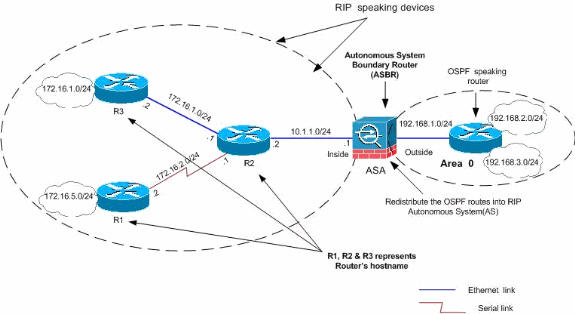
Network Diagram
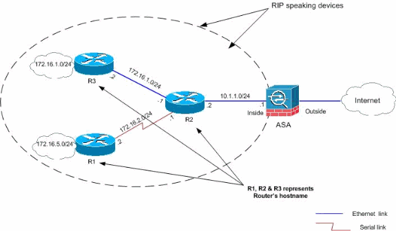
This document uses this network setup:
Configurations
This document uses these configurations:
ASDM Configuration
Adaptive Security Device Manager (ASDM) is a browser-based application used in order to configure and monitor the software on security appliances. ASDM is loaded from the security appliance, and then used to configure, monitor, and manage the device. You can also use the ASDM Launcher (Windows® only) in order to launch the ASDM application faster than the Java applet. This section describes the information you need to configure the features described in this document with ASDM.
Complete these steps in order to configure RIP in the Cisco ASA:
-
Log in to the Cisco ASA with ASDM.
-
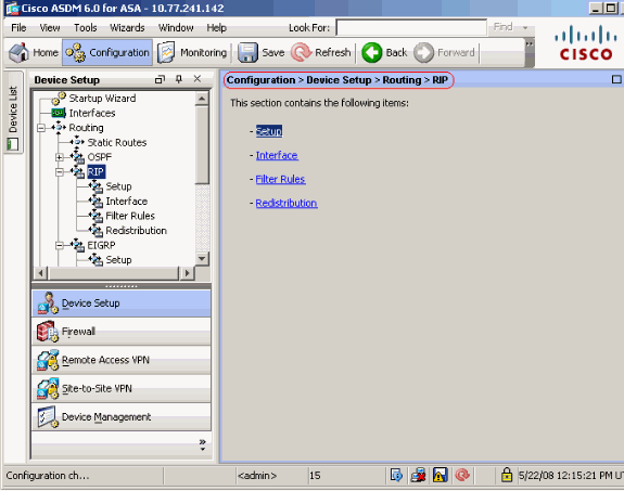
Choose Configuration > Device Setup > Routing > RIP in the ASDM interface, as shown in the screenshot.
-
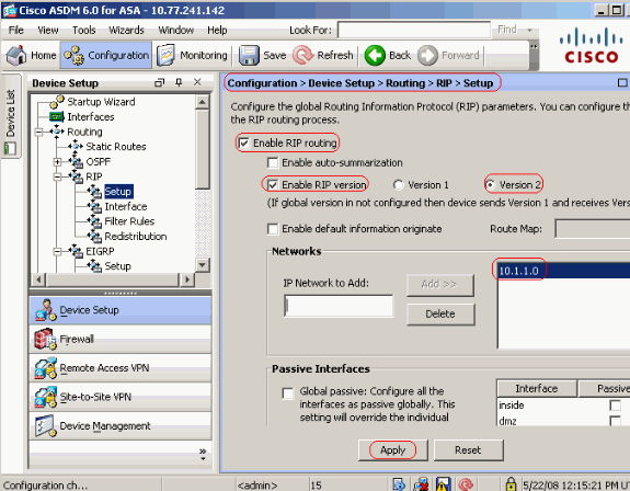
Choose Configuration > Device Setup > Routing > RIP > Setup in order to enable the RIP routing as shown.
-
Choose the check box Enable RIP routing.
-
Choose the check box Enable RIP version with radio button Version 2.
-
Under Networks tab, add the network 10.1.1.0.
-
Click Apply.
Fields
-
Enable RIP Routing—Check this check box inb order to enable RIP routing on the security appliance. When you enable RIP, it is enabled on all interfaces. If you check this check box, this also enables the other fields on this pane. Uncheck this check box in order to disable RIP routing on the security appliance.
-
Enable Auto-summarization—Clear this check box in order to disable automatic route summarization. Check this check box in order to reenable automatic route summarization. RIP Version 1 always uses automatic summarization. You cannot disable automatic summarization for RIP Version 1. If you use RIP Version 2, you can turn off automatic summarization if you uncheck this check box. Disable automatic summarization if you must perform routing between disconnected subnets. When automatic summarization is disabled, subnets are advertised.
-
Enable RIP version—Check this check box in order to specify the version of RIP used by the security appliance. If this check box is cleared, then the security appliance sends RIP Version 1 updates and accepts RIP Version 1 and Version 2 updates. This setting can be overridden on a per-interface basis in the Interface pane.
-
Version 1—Specifies that the security appliance only sends and receives RIP Version 1 updates. Any version 2 updates received are dropped.
-
Version 2—Specifies that the security appliance only sends and receives RIP Version 2 updates. Any version 1 updates received are dropped.
-
-
Enable default information originate—Check this check box in order to generate a default route into the RIP routing process. You can configure a route map that must be satisfied before the default route can be generated.
-
Route-map—Enter the name of the route map in order to apply. The routing process generates the default route if the route map is satisfied.
-
-
IP Network to Add—Defines a network for the RIP routing process. The network number specified must not contain any subnet information. There is no limit to the number of network you can add to the security appliance configuration. RIP routing updates is sent and received only through interfaces on the specified networks. Also, if the network of an interface is not specified, the interface is not advertised in any RIP updates.
-
Add—Click this button in order to add the specified network to the list of networks.
-
Delete—Click this button in order to remove the selected network from the list of networks
-
-
Configure interfaces as passive globally—Check this check box to set all interfaces on the security appliance to passive RIP mode. The security appliance listens for RIP routing broadcasts on all interfaces and uses that information to populate the routing tables but do not broadcast routing updates. Use the Passive Interfaces table in order to set specific interfaces to passive RIP.
-
Passive Interfaces table—Lists the configured interfaces on the security appliance. Check the check box in the Passive column for those interfaces you want to operate in passive mode. The other interfaces still send and receive RIP broadcasts.
-
-
Configure RIP Authentication
The Cisco ASA supports MD5 authentication of routing updates from the RIP v2 routing protocol. The MD5 keyed digest in each RIP packet prevents the introduction of unauthorized or false routing messages from unapproved sources. The addition of authentication to your RIP messages ensures that your routers and the Cisco ASA only accept routing messages from other routing devices that are configured with the same pre-shared key. Without this authentication configured, if you introduce another routing device with different or contrary route information on to the network, the routing tables on your routers or Cisco ASA can become corrupt, and a denial of service attack can ensue. When you add authentication to the RIP messages sent between your routing devices, which includes the ASA, it prevents the purposeful or accidental addition of another router to the network and any problem.
RIP route authentication is configured on a per-interface basis. All RIP neighbors on interfaces configured for RIP message authentication must be configured with the same authentication mode and key.
Complete these steps in order to enable RIP MD5 authentication on the Cisco ASA.
-
On ASDM, choose Configuration > Device Setup > Routing > RIP > Interface and choose the inside interface with mouse. Click Edit.

-
Choose the Enable authentication key checkbox and then enter the Key value and Key ID value.
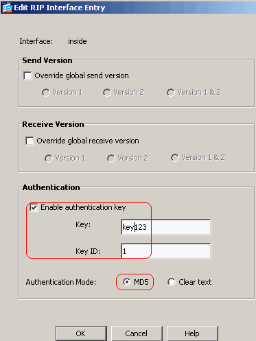
Click OK and then Apply.
Cisco ASA CLI Configuration
| Cisco ASA |
|---|
ciscoasa#show running-config : Saved : ASA Version 8.0(2) ! hostname ciscoasa enable password 8Ry2YjIyt7RRXU24 encrypted names ! !--- Inside interface configuration interface Ethernet0/1 nameif inside security-level 100 ip address 10.1.1.1 255.255.255.0 !--- RIP authentication is configured on the inside interface. rip authentication mode md5 rip authentication key <removed> key_id 1 ! !--- Output Suppressed !--- Outside interface configuration interface Ethernet0/2 nameif outside security-level 0 ip address 192.168.1.2 255.255.255.0 !--- RIP Configuration router rip network 10.0.0.0 version 2 !--- This is the static default gateway configuration in !--- order to reach the Internet. route outside 0.0.0.0 0.0.0.0 192.168.1.1 1 |
Cisco IOS Router (R2) CLI Configuration
| Cisco IOS Router (R2) |
|---|
interface Ethernet0 ip address 10.1.1.2 255.255.255.0 ip rip authentication mode md5 ip rip authentication key-chain 1 ! router rip version 2 network 10.0.0.0 network 172.16.0.0 no auto-summary |
Cisco IOS Router (R1) CLI Configuration
| Cisco IOS Router (R1) |
|---|
router rip version 2 network 172.16.0.0 no auto-summary |
Cisco IOS Router (R3) CLI Configuration
| Cisco IOS Router (R3) |
|---|
router rip version 2 network 172.16.0.0 no auto-summary |
Redistribute into RIP with ASA
You can redistribute routes from the OSPF, EIGRP, static, and connected routing processes into the RIP routing process.
In this example, the redistribution of the OSPF routes into RIP with the network diagram is shown:
ASDM Configuration
Complete these steps:
-
OSPF Configuration
-
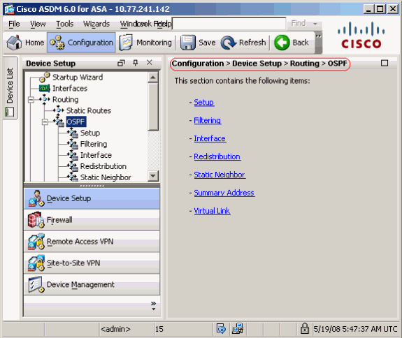
Choose Configuration > Device Setup > Routing > OSPF in the ASDM interface, as shown in the screenshot.
-
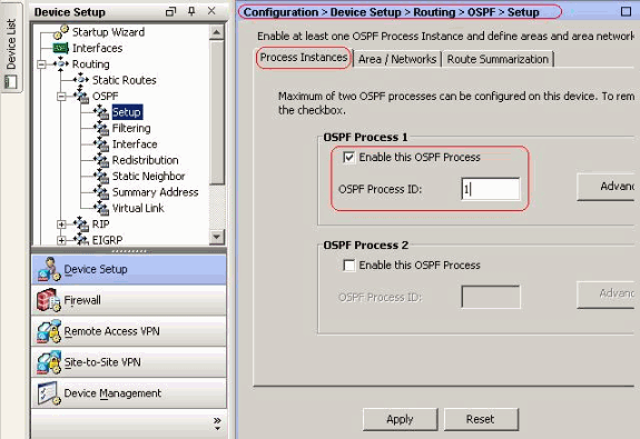
Enable the OSPF routing process on the Setup > Process Instances tab, as shown in the screenshot. In this example, the OSPF ID process is 1.
-
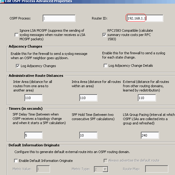
Click Advanced on the Setup > Process Instances tab in order to configure optional advanced OSPF routing process parameters. You can edit process-specific settings, such as the Router ID, Adjacency Changes, Administrative Route Distances, Timers, and Default Information Originate settings.
Click OK.
-
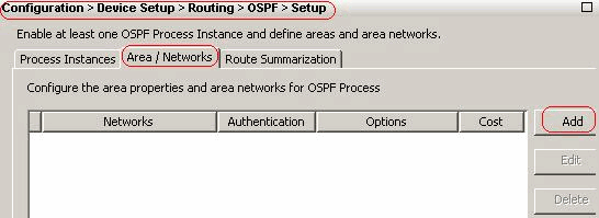
After you complete the previous steps, define the networks and interfaces that participate in OSPF routing on the Setup > Area/Networks tab. Click Add as shown in this screenshot.
-
This screen appears. In this example, the only network that we add is the outside network (192.168.1.0/24) since OSPF is enabled only on the outside interface.
Note: Only interfaces with an IP address that fall within the defined networks participate in the OSPF routing process.
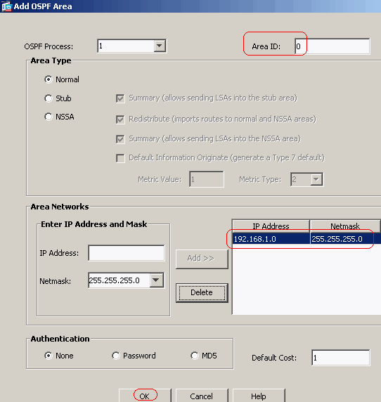
Click OK.
-
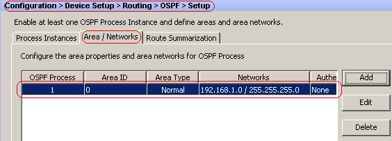
Click Apply.
-
-
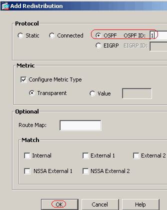
Choose Configuration > Device Setup > Routing > RIP > Redistribution > Add in order to redistribute OSPF routes into RIP.

-
Click OK and then Apply.
Equivalent CLI Configuration
| CLI Configuration of ASA for Redistribute OSPF into RIP AS |
|---|
router rip network 10.0.0.0 redistribute ospf 1 metric transparent version 2 ! router ospf 1 router-id 192.168.1.1 network 192.168.1.0 255.255.255.0 area 0 area 0 log-adj-changes |
You can see the routing table of the neighbor Cisco IOS Router(R2) after redistributing OSPF routes into RIP AS.
R2#show ip route
Codes: C - connected, S - static, I - IGRP, R - RIP, M - mobile, B - BGP
       D - EIGRP, EX - EIGRP external, O - OSPF, IA - OSPF inter area
       N1 - OSPF NSSA external type 1, N2 - OSPF NSSA external type 2
       E1 - OSPF external type 1, E2 - OSPF external type 2, E - EGP
       i - IS-IS, su - IS-IS summary, L1 - IS-IS level-1, L2 - IS-IS level-2
       ia - IS-IS inter area, * - candidate default, U - per-user static route
       o - ODR, P - periodic downloaded static route

Gateway of last resort is not set

     172.16.0.0/24 is subnetted, 4 subnets
R       172.16.10.0 [120/1] via 172.16.1.2, 00:00:25, Ethernet1
R       172.16.5.0 [120/1] via 172.16.2.2, 00:00:20, Serial1
C       172.16.1.0 is directly connected, Ethernet1
C       172.16.2.0 is directly connected, Serial1
     10.0.0.0/8 is variably subnetted, 2 subnets, 2 masks
C       10.1.1.0/24 is directly connected, Ethernet0
R       10.77.241.128/26 [120/1] via 10.1.1.1, 00:00:06, Ethernet0
R    192.168.1.0/24 [120/1] via 10.1.1.1, 00:00:05, Ethernet0
     192.168.2.0/32 is subnetted, 1 subnets
R       192.168.2.1 [120/12] via 10.1.1.1, 00:00:05, Ethernet0
     192.168.3.0/32 is subnetted, 1 subnets
R       192.168.3.1 [120/12] via 10.1.1.1, 00:00:05, Ethernet0

!--- Redistributed route advertised by Cisco ASA
Verify
Complete these steps in order to verify your configuration:
-
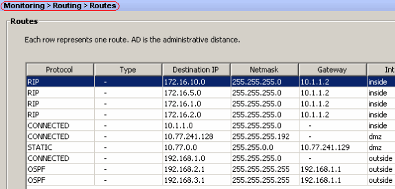
You can verify the routing table if you navigate to Monitoring > Routing > Routes. In this screenshot, you can see that the 172.16.1.0/24, 172.16.2.0/24, 172.16.5.0/24 and 172.16.10.0/24 networks are learned through R2 (10.1.1.2) with RIP.
-
From the CLI, you can use the show route command in order to get the same output.
ciscoasa#show route

Codes: C - connected, S - static, I - IGRP, R - RIP, M - mobile, B - BGP
       D - EIGRP, EX - EIGRP external, O - OSPF, IA - OSPF inter area
       N1 - OSPF NSSA external type 1, N2 - OSPF NSSA external type 2
       E1 - OSPF external type 1, E2 - OSPF external type 2, E - EGP
       i - IS-IS, L1 - IS-IS level-1, L2 - IS-IS level-2, ia - IS-IS inter area
       * - candidate default, U - per-user static route, o - ODR
       P - periodic downloaded static route

Gateway of last resort is not set

R    172.16.10.0 255.255.255.0 [120/2] via 10.1.1.2, 0:00:10, inside
R    172.16.5.0 255.255.255.0 [120/2] via 10.1.1.2, 0:00:10, inside
R    172.16.1.0 255.255.255.0 [120/1] via 10.1.1.2, 0:00:10, inside
R    172.16.2.0 255.255.255.0 [120/1] via 10.1.1.2, 0:00:10, inside
C    10.1.1.0 255.255.255.0 is directly connected, inside
C    10.77.241.128 255.255.255.192 is directly connected, dmz
S    10.77.0.0 255.255.0.0 [1/0] via 10.77.241.129, dmz
C    192.168.1.0 255.255.255.0 is directly connected, outside
O    192.168.2.1 255.255.255.255 [110/11] via 192.168.1.1, 0:34:46, outside
O    192.168.3.1 255.255.255.255 [110/11] via 192.168.1.1, 0:34:46, outside
ciscoasa#
Troubleshoot
This section includes information about debug commands that can be useful to troubleshoot OSPF problems.
Troubleshooting Commands
The Output Interpreter Tool (registered customers only) (OIT) supports certain show commands. Use the OIT to view an analysis of show command output.
Note: Refer to Important Information on Debug Commands before you use debug commands.
-
debug rip events—Enables the debugging of RIP events
ciscoasa#debug rip events
rip_route_adjust for inside coming up
RIP: sending request on inside to 224.0.0.9
RIP: received v2 update from 10.1.1.2 on inside
     172.16.1.0255.255.255.0 via 0.0.0.0 in 1 hops
     172.16.2.0255.255.255.0 via 0.0.0.0 in 1 hops
     172.16.5.0255.255.255.0 via 0.0.0.0 in 2 hops
     172.16.10.0255.255.255.0 via 0.0.0.0 in 2 hops
RIP: Update contains 4 routes
RIP: received v2 update from 10.1.1.2 on inside
     172.16.1.0255.255.255.0 via 0.0.0.0 in 1 hops
     172.16.2.0255.255.255.0 via 0.0.0.0 in 1 hops
     172.16.5.0255.255.255.0 via 0.0.0.0 in 2 hops
     172.16.10.0255.255.255.0 via 0.0.0.0 in 2 hops
RIP: Update contains 4 routes
RIP: sending v2 flash update to 224.0.0.9 via dmz (10.77.241.142)
RIP: build flash update entries
        10.1.1.0 255.255.255.0 via 0.0.0.0, metric 1, tag 0
        172.16.1.0 255.255.255.0 via 0.0.0.0, metric 2, tag 0
        172.16.2.0 255.255.255.0 via 0.0.0.0, metric 2, tag 0
        172.16.5.0 255.255.255.0 via 0.0.0.0, metric 3, tag 0
        172.16.10.0 255.255.255.0 via 0.0.0.0, metric 3, tag 0
RIP: Update contains 5 routes
RIP: Update queued
RIP: sending v2 flash update to 224.0.0.9 via inside (10.1.1.1)
RIP: build flash update entries - suppressing null update
RIP: Update sent via dmz rip-len:112
RIP: sending v2 update to 224.0.0.9 via dmz (10.77.241.142)
RIP: build update entries
        10.1.1.0 255.255.255.0 via 0.0.0.0, metric 1, tag 0
        172.16.1.0 255.255.255.0 via 0.0.0.0, metric 2, tag 0
        172.16.2.0 255.255.255.0 via 0.0.0.0, metric 2, tag 0
        172.16.5.0 255.255.255.0 via 0.0.0.0, metric 3, tag 0
        172.16.10.0 255.255.255.0 via 0.0.0.0, metric 3, tag 0
        192.168.1.0 255.255.255.0 via 0.0.0.0, metric 1, tag 0
        192.168.2.1 255.255.255.255 via 0.0.0.0, metric 12, tag 0
        192.168.3.1 255.255.255.255 via 0.0.0.0, metric 12, tag 0
RIP: Update contains 8 routes
RIP: Update queued
RIP: sending v2 update to 224.0.0.9 via inside (10.1.1.1)
RIP: build update entries
        10.77.241.128 255.255.255.192 via 0.0.0.0, metric 1, tag 0
        192.168.1.0 255.255.255.0 via 0.0.0.0, metric 1, tag 0
        192.168.2.1 255.255.255.255 via 0.0.0.0, metric 12, tag 0
        192.168.3.1 255.255.255.255 via 0.0.0.0, metric 12, tag 0
RIP: Update contains 4 routes
RIP: Update queued
RIP: Update sent via dmz rip-len:172
RIP: Update sent via inside rip-len:92
RIP: received v2 update from 10.1.1.2 on inside
     172.16.1.0255.255.255.0 via 0.0.0.0 in 1 hops
     172.16.2.0255.255.255.0 via 0.0.0.0 in 1 hops
     172.16.5.0255.255.255.0 via 0.0.0.0 in 2 hops
     172.16.10.0255.255.255.0 via 0.0.0.0 in 2 hops
RIP: Update contains 4 routes
Related Information
Contact Cisco
- Open a Support Case

- (Requires a Cisco Service Contract)


 Feedback