Introduction
This document describes how to configure Site-to-Site VPN on Firepower Threat Defense (FTD) managed by FirePower Device Manager (FDM).
Prerequisites
Requirements
Cisco recommends that you have knowledge of these topics:
- Basic understanding of VPN
- Experience with FDN
- Experience with Adaptive Security Appliance (ASA) command line
Components Used
The information in this document is based on these software and hardware versions:
- Cisco FTD 6.5
- ASA 9.10(1)32
- IKEv2
The information in this document was created from the devices in a specific lab environment. All of the devices used in this document started with a cleared (default) configuration. If your network is live, ensure that you understand the potential impact of any command.
Configure
Start with the configuration on FTD with FDM.
Define Protected Networks
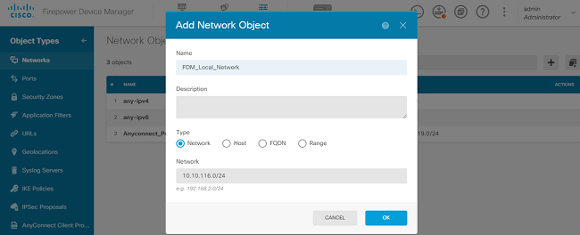
Navigate to Objects > Networks > Add New Network..
Configure objects for the LAN Networks from FDM GUI. Create an object for the local network behind the FDM device as shown in the image.
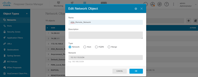
Create an object for the remote network behind the ASA device as shown in the image.
Configure Site-to-Site VPN
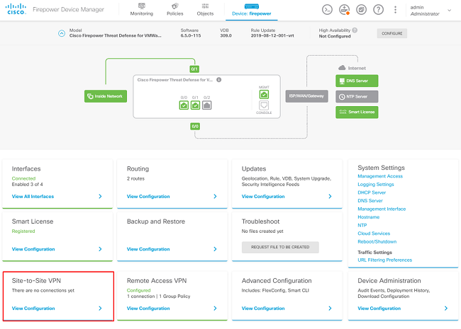
Navigate to Site-to-Site VPN > Create Site-to-Site Connection.
Go through the Site-to-Site wizard on FDM as shown in the image.

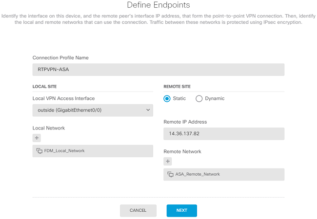
Give the Site-to-Site connection a connection profile name that is easily identifiable.
Choose the correct external interface for the FTD and then choose the Local network that needs to be encrypted across the site to site VPN.
Set the public interface of the remote peer. Then choose the remote peers' network that is encrypted across the Site-to-Site VPN as shown in the image.
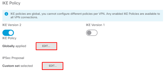
On the next page, choose the Edit button to set the Internet Key Exchange (IKE) parameters as shown in the image.
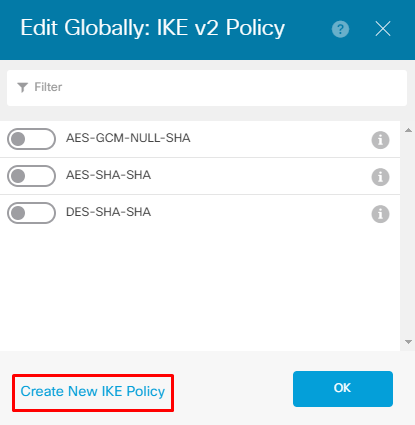
Choose the Create New IKE Policy button as shown in the image.
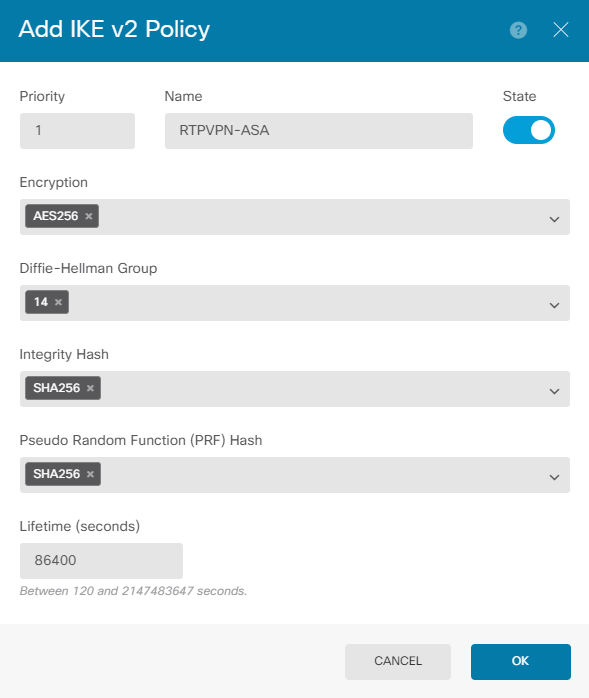
This guide uses these parameters for the IKEv2 initial exchange:
Encryption AES-256
Integrity SHA256
DH Group 14
PRF SHA256
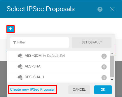
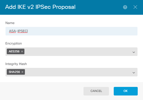
Once back on the main page, choose the Edit button for the IPSec Proposal. Create a new IPSec Proposal as shown in the image.
This guide uses these parameters for IPSec:
Encryption AES-256
Integrity SHA256
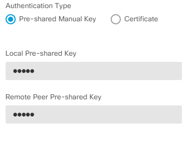
Set the authentication to pre-shared key and enter the Pre-Shared Key (PSK) that is used on both ends. In this guide, the PSK of Cisco is used as shown in the image.
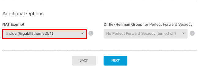
Set the internal NAT Exempt interface. If there are multiple inside interfaces that are used, a manual NAT Exempt rule needs to be created under the Policies > NAT.
On the final page, a summary of the Site-to-Site connection is displayed. Ensure that the correct IP addresses are selected, and the proper encryption parameters are used, and hit the finish button. Deploy the new Site-to-Site VPN.
The ASA configuration is completed with the use of the CLI.
ASA Configuration
- Enable IKEv2 on the outside interface of the ASA:
Crypto ikev2 enable outside
2. Create the IKEv2 Policy that defines the same parameters configured on the FTD:
Crypto ikev2 policy 1
 Encryption aes-256
 Integrity sha256
 Group 14
 Prf sha256
 Lifetime seconds 86400
3. Create a group policy that allows the IKEv2 protocol:
Group-policy FDM_GP internal
Group-policy FDM_GP attributes
Vpn-tunnel-protocol ikev2
4. Create a tunnel group for the peer FTD public IP address. Reference the group-policy, and specify the pre-shared-key:
Tunnel-group 172.16.100.10 type ipsec-l2l
Tunnel-group 172.16.100.10 general-attributes
 Default-group-policy FDM_GP
Tunnel-group 172.16.100.10 ipsec-attributes
 ikev2 local-authentication pre-shared-key cisco
 ikev2 remote-authentication pre-shared-key cisco
5. Create an access-list that defines the traffic to be encrypted: (FTDSubnet 10.10.116.0/24) (ASASubnet 10.10.110.0/24):
Object network FDMSubnet
 Subnet 10.10.116.0 255.255.255.0
Object network ASASubnet
 Subnet 10.10.110.0 255.255.255.0
Access-list ASAtoFTD extended permit ip object ASASubnet object FTDSubnet
6. Create an IKEv2 IPsec-proposal that references the algorithms specified on the FTD:
Crypto ipsec ikev2 ipsec-proposal FDM
 Protocol esp encryption aes-256
 Protocol esp integrity sha-256
7. Create a crypto map entry that ties together the configuration:
Crypto map outside_map 20 set peer 172.16.100.10
Crypto map outside_map 20 match address ASAtoFTD
Crypto map outside_map 20 set ikev2 ipsec-proposal FTD
Crypto map outside_map 20 interface outside
8. Create a NAT exemption statement that prevents the VPN traffic from being NATTED by the firewall:
Nat (inside,outside) 1 source static ASASubnet ASASubnet destination static FDMSubnet FDMSubnet
no-proxy-arp route-lookup
Verify
Use this section in order to confirm that your configuration works properly.
Attempt to initiate traffic through the VPN tunnel. With access to the command line of the ASA or FTD, this can be done with the packet tracer command. When you use the packet-tracer command to bring up the VPN tunnel, it must be run twice in order to verify whether the tunnel comes up. The first time the command is issued, the VPN tunnel is down so the packet-tracer command fails with VPN encrypt DROP. Do not use the inside IP address of the firewall as the source IP address in the packet-tracer as this always fails.
firepower# packet-tracer input inside icmp 10.10.116.10 8 0 10.10.110.10

Phase: 9
Type: VPN
Subtype: encrypt
Result: DROP
Config:
Additional Information:


firepower# packet-tracer input inside icmp 10.10.116.10 8 0 10.10.110.10

Phase: 1
Type: ROUTE-LOOKUP
Subtype: Resolve Egress Interface
Result: ALLOW
Config:
Additional Information:
found next-hop 172.16.100.1 using egress ifc outside

Phase: 2
Type: UN-NAT
Subtype: static
Result: ALLOW
Config:
nat (inside,outside) source static |s2sAclSrcNwgV4|c9911223-779d-11ea-9c1b-5ddd47126971 |s2sAclSrcNwgV4|c9911223-779d-11ea-9c1b-5ddd47126971 destination static |s2sAclDestNwgV4|c9911223-779d-11ea-9c1b-5ddd47126971 |s2sAclDestNwgV4|c9911223-779d-11ea-9c1b-5ddd47126971 no-proxy-arp route-lookup
Additional Information:
NAT divert to egress interface outside
Untranslate 10.10.110.10/0 to 10.10.110.10/0

Phase: 3
Type: ACCESS-LIST
Subtype: log
Result: ALLOW
Config:
access-group NGFW_ONBOX_ACL global
access-list NGFW_ONBOX_ACL advanced trust object-group |acSvcg-268435457 ifc inside any ifc outside any rule-id 268435457 event-log both
access-list NGFW_ONBOX_ACL remark rule-id 268435457: ACCESS POLICY: NGFW_Access_Policy
access-list NGFW_ONBOX_ACL remark rule-id 268435457: L5 RULE: Inside_Outside_Rule
object-group service |acSvcg-268435457
service-object ip
Additional Information:

Phase: 4
Type: NAT
Subtype:
Result: ALLOW
Config:
nat (inside,outside) source static |s2sAclSrcNwgV4|c9911223-779d-11ea-9c1b-5ddd47126971 |s2sAclSrcNwgV4|c9911223-779d-11ea-9c1b-5ddd47126971 destination static |s2sAclDestNwgV4|c9911223-779d-11ea-9c1b-5ddd47126971 |s2sAclDestNwgV4|c9911223-779d-11ea-9c1b-5ddd47126971 no-proxy-arp route-lookup
Additional Information:
Static translate 10.10.116.10/0 to 10.10.116.10/0

Phase: 9
Type: VPN
Subtype: encrypt
Result: ALLOW
Config:
Additional Information:

Result:
input-interface: inside
input-status: up
input-line-status: up
output-interface: outside
output-status: up
output-line-status: up
Action: allow
In order to monitor the tunnel status, navigate to the CLI of the FTD or ASA.
From the FTD CLI, verify phase-1 and phase-2 with the command show crypto ikev2 sa.
> show crypto ikev2 sa

IKEv2 SAs:

Session-id:1, Status:UP-ACTIVE, IKE count:1, CHILD count:1

Tunnel-id Local                                               Remote                                                  Status         Role
  3821043 172.16.100.10/500                                    192.168.200.10/500                                         READY    INITIATOR
      Encr: AES-CBC, keysize: 256, Hash: SHA256, DH Grp:14, Auth sign: PSK, Auth verify: PSK
      Life/Active Time: 86400/1150 sec
Child sa: local selector  10.10.116.0/0 - 10.10.116.255/65535
          remote selector 10.10.110.0/0 - 10.10.110.255/65535
          ESP spi in/out: 0x7398dcbd/0x2303b0c0
Troubleshoot
This section provides information you can use in order to troubleshoot your configuration.
Initial Connectivity Issues
When you build a VPN, there are two sides negotiating the tunnel. Therefore, it is best to get both sides of the conversation when you troubleshoot any type of tunnel failure. A detailed guide on how to debug IKEv2 tunnels can be found here: How to Debug IKEv2 VPNs
The most common cause of tunnel failures is a connectivity issue. The best way to determine this is to take packet captures on the device.
Use this command to take packet captures on the device:
Capture capout interface outside match ip host 172.16.100.10 host 192.168.200.10
Once the capture is in place, try to send traffic over the VPN and check for bi-directional traffic in the packet capture.
Review the packet capture with the command show cap capout.
firepower# show cap capout

4 packets captured

   1: 01:21:06.763983       172.16.100.10.500 > 192.168.200.10.500:  udp 574
   2: 01:21:06.769415       192.168.200.10.500 > 172.16.100.10.500:  udp 619
   3: 01:21:06.770666       172.16.100.10.500 > 192.168.200.10.500:  udp 288
   4: 01:21:06.773748       192.168.200.10.500 > 172.16.100.10.500:  udp 256
Traffic-Specific Issues
Common traffic issues that users experience are:
- Routing issues behind the FTD - internal network unable to route packets back to the assigned IP addresses and VPN clients.
- Access control lists blocking traffic.
- Network Address Translation (NAT) not being bypassed for VPN traffic.
Related Information
For further information regarding Site-to-Site VPNs on the FTD managed by FDM, you can find the full configuration guide here.


 Feedback