Introduction
This document describes how to configure Site to Site VPN on Firepower Threat Defense (FTD) managed by FMC.
Prerequisites
Requirements
You must have knowledge of these topics:
- Basic understanding of VPN
- Experience with Firepower Management Center
- Experience with ASA command line
Components Used
The information in this document is based on these software and hardware versions:
- Cisco FTD 6.5
- ASA 9.10(1)32
- IKEv2
The information in this document was created from the devices in a specific lab environment. All of the devices used in this document started with a cleared (default) configuration. If your network is live, ensure that you understand the potential impact of any command.
Configuration
Start with the configuration on FTD with FirePower Management Center.
Step 1. Define the VPN Topology.
1. Navigate to Devices > VPN > Site To Site. Under Add VPN, click Firepower Threat Defense Device, as shown in this image.

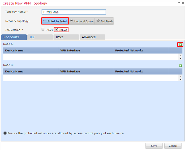
2. Create New VPN Topology box appears. Give VPN a name that is easily identifiable.
Network Topology: Point to Point
IKE Version: IKEv2
In this example when you select endpoints, Node A is the FTD, and Node B is the ASA. Click on the green plus button to add devices to the topology, as shown in this image.
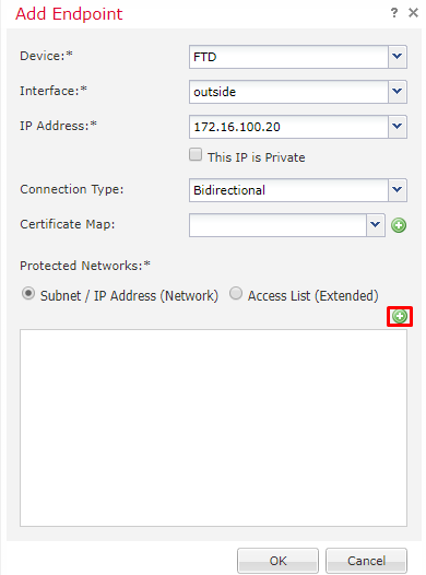
3. Add the FTD as the first endpoint.
Choose the interface that a crypto map is placed on. The IP address then auto-populates from the device configuration.
Click the green plus under Protected Networks, as shown in this image, to select what subnets are to be encrypted in this VPN.
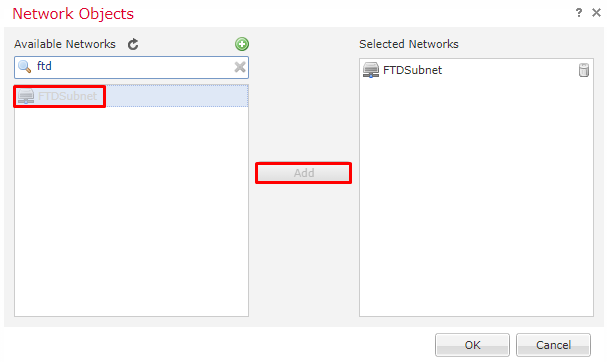
4. Click on green plus and a Network Object is created here.
5. Add all the subnets local to the FTD that needs to be encrypted. Click Add to move them to the Selected Networks. Now click OK, as shown in this image.
FTDSubnet = 10.10.113.0/24
Node A: (FTD) endpoint is complete. Click the green plus for Node B, as shown in the image.
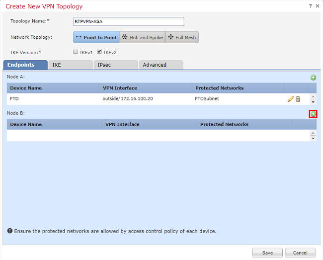
Node B is an ASA. Devices that are not managed by the FMC are considered Extranet.
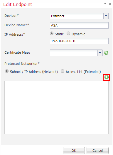
6. Add a device name and IP address. Click on the green plus to add protected networks, as shown in the image.
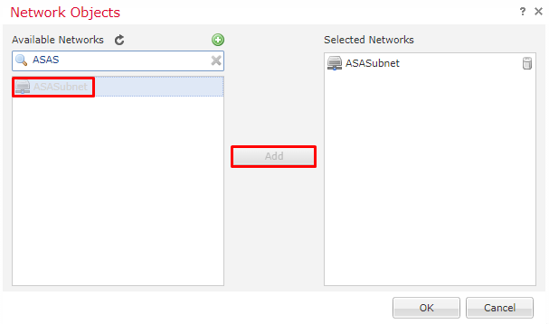
7. As shown in this image, select the ASA subnets that need to be encrypted and add them to the selected networks.
ASASubnet = 10.10.110.0/24
Step 2. Configure IKE Parameters.
Now both endpoints are in place go through the IKE/IPSEC configuration.
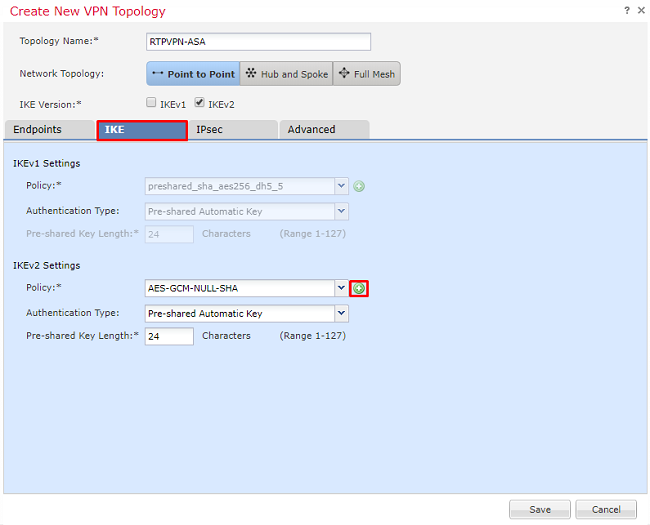
1. Under the IKE tab, specify the parameters that are used for the IKEv2 initial exchange. Click the green plus to create a new IKE policy, as shown in the image.
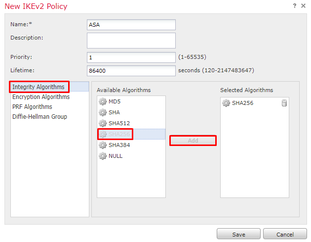
2. In the new IKE policy, specify a priority number as well as the lifetime of phase 1 of the connection. This document uses these parameters for the initial exchange: Integrity (SHA256), Encryption (AES-256), PRF (SHA256), and Diffie-Hellman Group (Group 14)
Note: All IKE policies on the device are sent to the remote peer regardless of what is in the selected policy section. The first IKE Policy matched by the remote peer is selected for the VPN connection. Choose which policy is sent first using the priority field. Priority 1 is sent first.
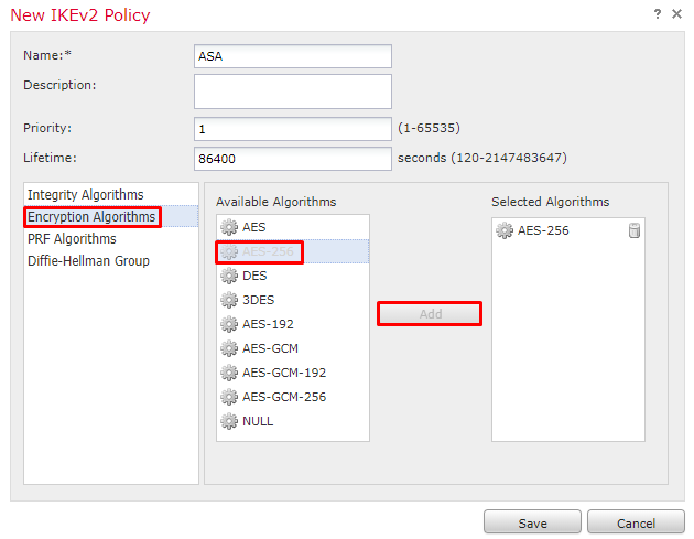
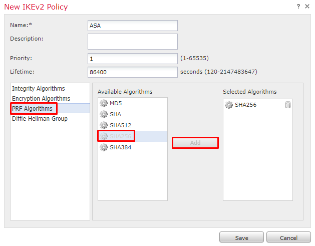
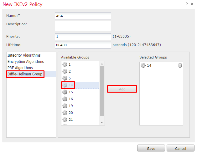
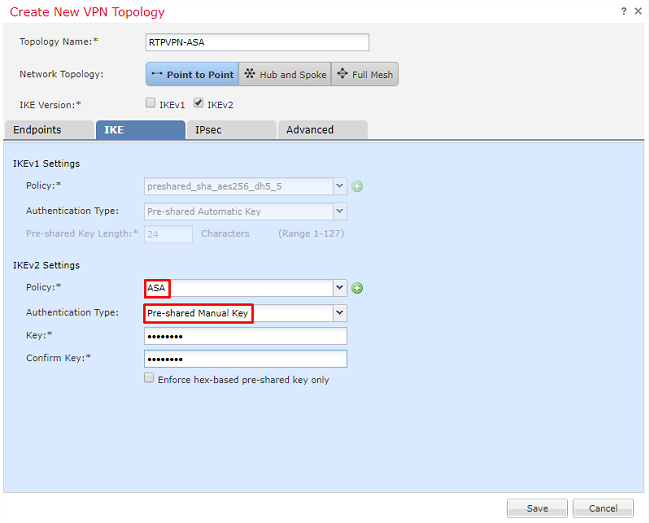
3. Once the parameters are added, select this policy, and choose the Authentication Type.
4. Choose pre-shared-key manual. For this document, the PSK cisco123 is used.
Step 3. Configure IPsec Parameters.
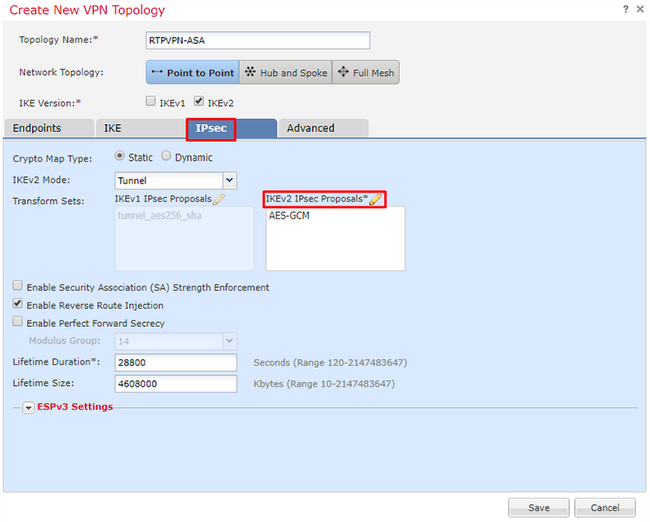
1. Under IPsec, click on the pencil to edit the transform set and create a new IPsec Proposal, as shown in this image.
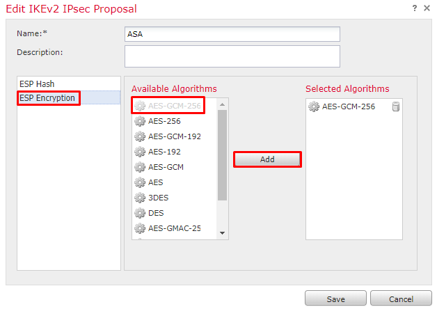
2. In order to create a new IKEv2 IPsec Proposal, click the green plus and input the phase 2 parameters.
Select ESP Encryption > AES-GCM-256. When the GCM algorithm is used for encryption, a Hash algorithm is not needed. With GCM the hash function is built-in.
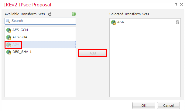
3. Once the new IPsec proposal has been created add it to the selected transform sets.
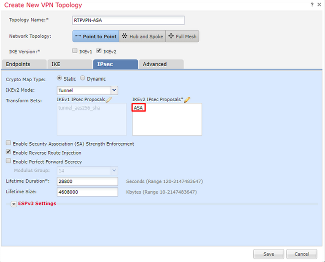
The newly selected IPsec proposal is now listed under the IKEv2 IPsec Proposals.
If needed, the phase 2 lifetime and PFS can be edited here. For this example, the lifetime is set as default and PFS disabled.
Optional- You must complete either complete the option to Bypass Access Control or Create an Access Control Policy.
Step 4. Bypass Access Control.
Optionally, sysopt permit-vpn can be enabled under the Advanced > Tunnel.
This removes the possibility to use the Access Control Policy to inspect traffic coming from the users. VPN filters or downloadable ACLs can still be used to filter user traffic. This is a global command and applies to all VPNs if this checkbox is enabled.
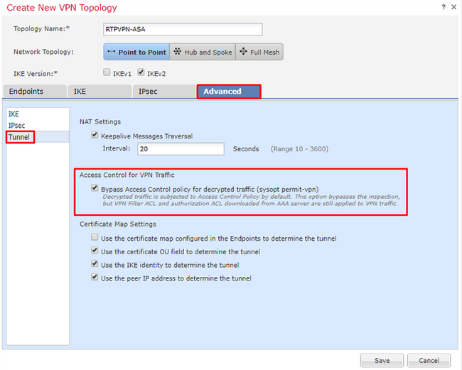
If sysopt permit-vpn is not enabled then an access control policy must be created to allow the VPN traffic through the FTD device. If sysopt permit-vpn is enabled skip creating an access control policy.
Step 5. Create an Access Control Policy.
Under Access Control Policies, navigate to Policies > Access Control > Access Control and select the Policy that targets the FTD device. In order to add a Rule, click Add Rule, as shown in the image here.
Traffic must be allowed from the internal network out to the external network and from the external network into the internal network. Create one rule to do both or create two rules to keep them separate. In this example, one rule is created to do both.
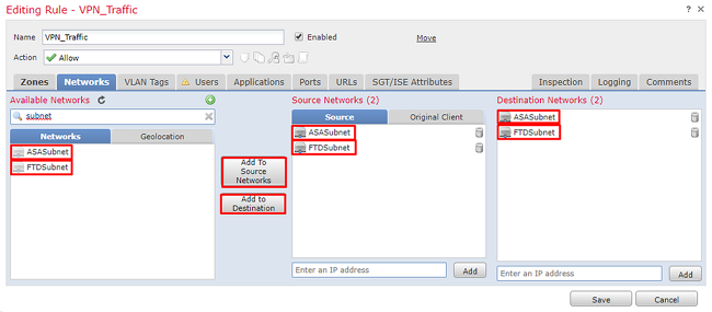

Step 6. Configure NAT Exemption.
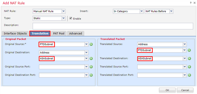
Configure a NAT Exemption statement for the VPN traffic. NAT exemption must be in place to keep VPN traffic from hitting another NAT statement and incorrectly translating VPN traffic.
1. Navigate to Devices > NAT, select the NAT policy that targets the FTD. Create a new rule as you click the Add Rule button.

2. Create a new Static Manual NAT Rule. Reference the inside and outside interfaces.
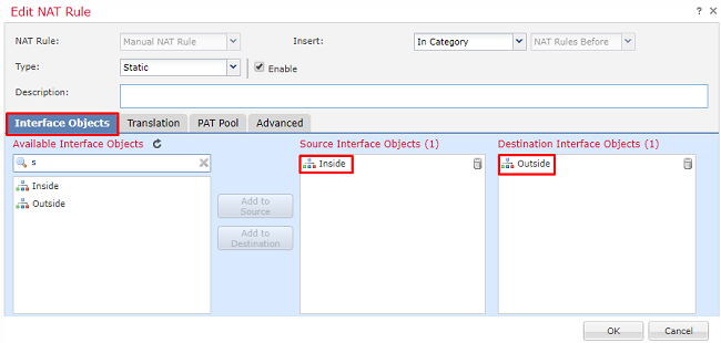
3. Under the Translation tab and select the source and destination subnets. As this is a NAT exemption rule, make the original source/destination and the translated source/destination the same, as shown in this image:
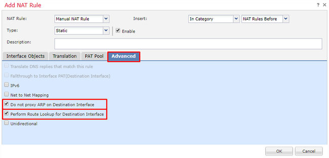
4. Lastly, move to the Advanced tab and enabled no-proxy-arp and route-lookup.
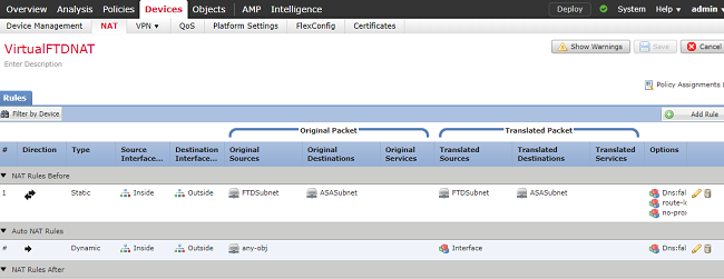
5. Save this rule and look at the final results in the NAT list.
6. Once the configuration is completed, save and deploy the configuration to the FTD.
Step 7. Configure the ASA.
- Enable IKEv2 on the outside interface of the ASA:
Crypto ikev2 enable outside
2. Create the IKEv2 Policy that defines the same parameters configured on the FTD:
Crypto ikev2 policy 1
 Encryption aes-256
 Integrity sha256
 Group 14
 Prf sha256
 Lifetime seconds 86400
3. Create a group-policy allowing the ikev2 protocol:
Group-policy FTD_GP internal
Group-policy FTD_GP attributes
 Vpn-tunnel-protocol ikev2
4. Create a tunnel group for the peer FTD public IP address. Reference the group-policy and specify the pre-shared-key:
Tunnel-group 172.16.100.20 type ipsec-l2l
Tunnel-group 172.16.100.20 general-attributes
Default-group-policy FTD_GP
Tunnel-group 172.16.100.20 ipsec-attributes
 ikev2 local-authentication pre-shared-key cisco123
 ikev2 remote-authentication pre-shared-key cisco123
5. Create an access-list that defines the traffic to be encrypted: (FTDSubnet 10.10.113.0/24) (ASASubnet 10.10.110.0/24)
Object network FTDSubnet
 Subnet 10.10.113.0 255.255.255.0
Object network ASASubnet
 Subnet 10.10.110.0 255.255.255.0
Access-list ASAtoFTD extended permit ip object ASASubnet object FTDSubnet
6. Create an ikev2 ipsec-proposal referencing the algorithms specified on the FTD:
Crypto ipsec ikev2 ipsec-proposal FTD
 Protocol esp encryption aes-gcm-256
7. Create a crypto map entry that ties together the configuration:
Crypto map outside_map 10 set peer 172.16.100.20
Crypto map outside_map 10 match address ASAtoFTD
Crypto map outside_map 10 set ikev2 ipsec-proposal FTD
Crypto map outside_map 10 interface outside
8. Create a NAT exemption statement that prevents the VPN traffic from being NATTED by the firewall:
Nat (inside,outside) 1 source static ASASubnet ASASubnet destination static FTDSubnet FTDSubnet no-proxy-arp route-lookup
Verify
Note: At this time there is no way to review VPN tunnel status from the FMC. There is an enhancement request for this capability Cisco bug ID CSCvh77603.
Attempt to initiate traffic through the VPN tunnel. With access to the command line of the ASA or FTD, this can be done with the packet tracer command. When using the packet-tracer command to bring up the VPN tunnel it must be run twice to verify the tunnel comes up. The first time the command is issued the VPN tunnel is down so the packet-tracer command fails with VPN encrypt DROP. Do not use the inside IP address of the firewall as the source IP address in the packet-tracer as this always fails.
firepower# packet-tracer input inside icmp 10.10.113.10 8 0 10.10.110.10

Phase: 10
Type: VPN
Subtype: encrypt
Result: DROP
Config:
Additional Information:


firepower# packet-tracer input inside icmp 10.10.113.10 8 0 10.10.110.10

Phase: 1
Type: ROUTE-LOOKUP
Subtype: Resolve Egress Interface
Result: ALLOW
Config:
Additional Information:
found next-hop 172.16.100.1 using egress ifc outside

Phase: 2
Type: UN-NAT
Subtype: static
Result: ALLOW
Config:
nat (Inside,outside) source static FTDSubnet FTDSubnet destination static ASASubnet ASASubnet no-proxy-arp route-lookup
Additional Information:
NAT divert to egress interface outside
Untranslate 10.10.110.10/0 to 10.10.110.10/0

Phase: 3
Type: ACCESS-LIST
Subtype: log
Result: ALLOW
Config:
access-group CSM_FW_ACL_ global
access-list CSM_FW_ACL_ advanced permit ip ifc Inside object-group FMC_INLINE_src_rule_268436483 ifc outside object-group FMC_INLINE_dst_rule_268436483 rule-id 268436483
access-list CSM_FW_ACL_ remark rule-id 268436483: ACCESS POLICY: FTD-Access-Control-Policy - Mandatory
access-list CSM_FW_ACL_ remark rule-id 268436483: L7 RULE: VPN_Traffic
object-group network FMC_INLINE_src_rule_268436483
description: Auto Generated by FMC from src of UnifiedNGFWRule# 1 (FTD-Access-Control-Policy/mandatory)
network-object object ASASubnet
network-object object FTDSubnet
object-group network FMC_INLINE_dst_rule_268436483
description: Auto Generated by FMC from dst of UnifiedNGFWRule# 1 (FTD-Access-Control-Policy/mandatory)
network-object object ASASubnet
network-object object FTDSubnet
Additional Information:
This packet is sent to snort for additional processing where a verdict is reached

Phase: 5
Type: NAT
Subtype:
Result: ALLOW
Config:
nat (Inside,outside) source static FTDSubnet FTDSubnet destination static ASASubnet ASASubnet no-proxy-arp route-lookup
Additional Information:
Static translate 10.10.113.10/0 to 10.10.113.10/0

Phase: 10
Type: VPN
Subtype: encrypt
Result: ALLOW
Config:
Additional Information:

Result:
input-interface: Inside
input-status: up
input-line-status: up
output-interface: outside
output-status: up
output-line-status: up
Action: allow
In order to monitor the tunnel status navigate to the CLI of the FTD or ASA.
From the FTD CLI verify phase-1 and phase-2 with this command:
Show crypto ikev2 sa
> show crypto ikev2 sa

IKEv2 SAs:

Session-id:4, Status:UP-ACTIVE, IKE count:1, CHILD count:1

Tunnel-id Local                                               Remote                                                  Status         Role
  9528731 172.16.100.20/500                                    192.168.200.10/500                                         READY    INITIATOR
      Encr: AES-CBC, keysize: 256, Hash: SHA256, DH Grp:14, Auth sign: PSK, Auth verify: PSK
      Life/Active Time: 86400/118 sec
Child sa: local selector  10.10.113.0/0 - 10.10.113.255/65535
          remote selector 10.10.110.0/0 - 10.10.110.255/65535
          ESP spi in/out: 0x66be357d/0xb74c8753
Troubleshoot and Debug
Initial Connectivity Issues
When building a VPN there are two sides negotiating the tunnel. Therefore, it is best to get both sides of the conversation when you troubleshoot any type of tunnel failure. A detailed guide on how to debug IKEv2 tunnels can be found here: How to debug IKEv2 VPNs
The most common cause of tunnel failures is a connectivity issue. The best way to determine this is to take packet captures on the device. Use this command to take packet captures on the device:
Capture capout interface outside match ip host 172.16.100.20 host 192.168.200.10
Once the capture is in place, try to send traffic over the VPN and check for bi-directional traffic in the packet capture.
Review the packet capture with this command:
show cap capout
firepower# show cap capout

4 packets captured

   1: 11:51:12.059628       172.16.100.20.500 > 192.168.200.10.500:  udp 690
   2: 11:51:12.065243       192.168.200.10.500 > 172.16.100.20.500:  udp 619
   3: 11:51:12.066692       172.16.100.20.500 > 192.168.200.10.500:  udp 288
   4: 11:51:12.069835       192.168.200.10.500 > 172.16.100.20.500:  udp 240
Traffic-Specific Issues
Common traffic issues that you experience are:
- Routing issues behind the FTD -- internal network unable to route packets back to the assigned IP addresses and VPN clients.
- Access control lists blocking traffic.
- Network Address Translation not being bypassed for VPN traffic.
For further information regarding VPNs on the FTD managed by FMC, you can find the full configuration guide here: FTD managed by FMC configuration guide


 Feedback