Configuring the Cisco VPN 3000 Concentrator to a Cisco Router
Available Languages
Contents
Introduction
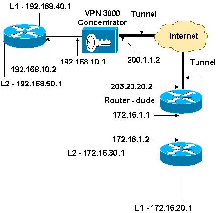
This sample configuration shows how to connect a private network behind a router that runs Cisco IOS® software to a private network behind the Cisco VPN 3000 Concentrator. The devices on the networks know each other by their private addresses.
Prerequisites
Requirements
There are no specific requirements for this document.
Components Used
The information in this document is based on these software and hardware versions:
-
Cisco 2611 router with Cisco IOS Software Release 12.3.(1)a
Note: Make sure that Cisco 2600 Series routers are installed with a crypto IPsec VPN IOS image that supports the VPN feature.
-
Cisco VPN 3000 Concentrator with 4.0.1 B
The information in this document was created from the devices in a specific lab environment. All of the devices used in this document started with a cleared (default) configuration. If your network is live, make sure that you understand the potential impact of any command.
Conventions
Refer to Cisco Technical Tips Conventions for more information on document conventions.
Configure
In this section, you are presented with the information to configure the features described in this document.
Note: Use the Command Lookup Tool (registered customers only) to find more information on the commands used in this document.
Network Diagram
This document uses this network setup.
Configurations
This document uses this configuration.
| Router Configuration |
|---|
version 12.3 service timestamps debug datetime msec service timestamps log datetime msec no service password-encryption ! hostname dude ! memory-size iomem 15 ip subnet-zero ! ip audit notify log ip audit po max-events 100 ! !--- IKE policies. crypto isakmp policy 1 encr 3des hash md5 authentication pre-share group 2 crypto isakmp key cisco123 address 200.1.1.2 ! !--- IPsec policies. crypto ipsec transform-set to_vpn esp-3des esp-md5-hmac ! crypto map to_vpn 10 ipsec-isakmp set peer 200.1.1.2 set transform-set to_vpn !--- Traffic to encrypt. match address 101 ! interface Ethernet0/0 ip address 203.20.20.2 255.255.255.0 ip nat outside half-duplex crypto map to_vpn ! interface Ethernet0/1 ip address 172.16.1.1 255.255.255.0 ip nat inside half-duplex ! ip nat pool mypool 203.20.20.3 203.20.20.3 netmask 255.255.255.0 ip nat inside source route-map nonat pool mypool overload ip http server no ip http secure-server ip classless ip route 0.0.0.0 0.0.0.0 203.20.20.1 ip route 172.16.20.0 255.255.255.0 172.16.1.2 ip route 172.16.30.0 255.255.255.0 172.16.1.2 ! !--- Traffic to encrypt. access-list 101 permit ip 172.16.1.0 0.0.0.255 192.168.10.0 0.0.0.255 access-list 101 permit ip 172.16.1.0 0.0.0.255 192.168.40.0 0.0.0.255 access-list 101 permit ip 172.16.1.0 0.0.0.255 192.168.50.0 0.0.0.255 access-list 101 permit ip 172.16.20.0 0.0.0.255 192.168.10.0 0.0.0.255 access-list 101 permit ip 172.16.20.0 0.0.0.255 192.168.40.0 0.0.0.255 access-list 101 permit ip 172.16.20.0 0.0.0.255 192.168.50.0 0.0.0.255 access-list 101 permit ip 172.16.30.0 0.0.0.255 192.168.10.0 0.0.0.255 access-list 101 permit ip 172.16.30.0 0.0.0.255 192.168.40.0 0.0.0.255 access-list 101 permit ip 172.16.30.0 0.0.0.255 192.168.50.0 0.0.0.255 !--- Traffic to except from the NAT process. access-list 110 deny ip 172.16.1.0 0.0.0.255 192.168.10.0 0.0.0.255 access-list 110 deny ip 172.16.1.0 0.0.0.255 192.168.40.0 0.0.0.255 access-list 110 deny ip 172.16.1.0 0.0.0.255 192.168.50.0 0.0.0.255 access-list 110 deny ip 172.16.20.0 0.0.0.255 192.168.10.0 0.0.0.255 access-list 110 deny ip 172.16.20.0 0.0.0.255 192.168.40.0 0.0.0.255 access-list 110 deny ip 172.16.20.0 0.0.0.255 192.168.50.0 0.0.0.255 access-list 110 deny ip 172.16.30.0 0.0.0.255 192.168.10.0 0.0.0.255 access-list 110 deny ip 172.16.30.0 0.0.0.255 192.168.40.0 0.0.0.255 access-list 110 deny ip 172.16.30.0 0.0.0.255 192.168.50.0 0.0.0.255 access-list 110 permit ip 172.16.1.0 0.0.0.255 any ! route-map nonat permit 10 match ip address 110 ! line con 0 line aux 0 line vty 0 4 ! end |
VPN Concentrator Configuration
In this lab setting, the VPN Concentrator is first accessed through the console port and a minimal configuration is added so that the further configuration can be done through the graphical user interface (GUI).
Choose Administration > System Reboot > Schedule reboot > Reboot with Factory/Default Configuration to ensure that there is no existing configuration in the VPN Concentrator.
The VPN Concentrator appears in Quick Configuration, and these items are configured after the reboot:
-
Time/Date
-
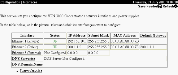
Interfaces/Masks in Configuration > Interfaces (public=200.1.1.2/24, private=192.168.10.1/24)
-
Default Gateway in Configuration > System > IP routing > Default_Gateway (200.1.1.1)
At this point, the VPN Concentrator is accessible through HTML from the inside network.
Note: Because the VPN Concentrator is managed from outside, you also have to select:
-
Configuration > Interfaces > 2-public > Select IP Filter > 1. Private (Default).
-
Administration > Access Rights > Access Control List > Add Manager Workstation to add the IP address of the external manager.
This is not necessary unless you manage the VPN Concentrator from outside.
-
Choose Configuration > Interfaces to recheck the interfaces after you bring up the GUI.
-
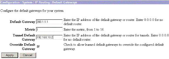
Choose Configuration > System > IP Routing > Default Gateways to configure the Default (Internet) Gateway and the Tunnel Default (inside) Gateway for IPsec to reach the other subnets in the private network.
-
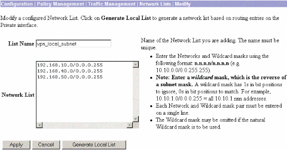
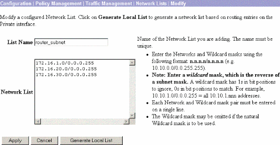
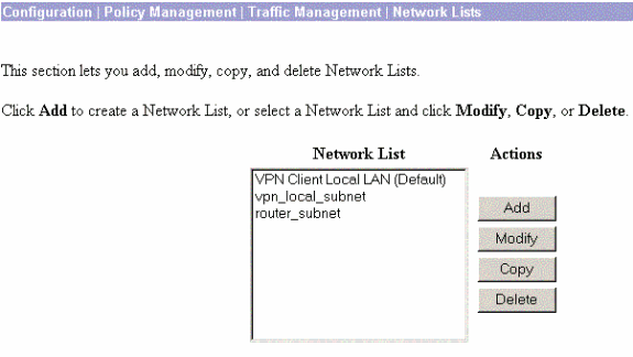
Choose Configuration > Policy Management > Network Lists to create the network lists that define the traffic to be encrypted.
These are the local networks:
These are the remote networks:
-
When completed, these are the two network lists:
Note: If the IPsec tunnel does not come up, check to see if the interesting traffic matches on both sides. The interesting traffic is defined by the access list on the router and PIX boxes. They are defined by network lists in the VPN Concentrators.
-
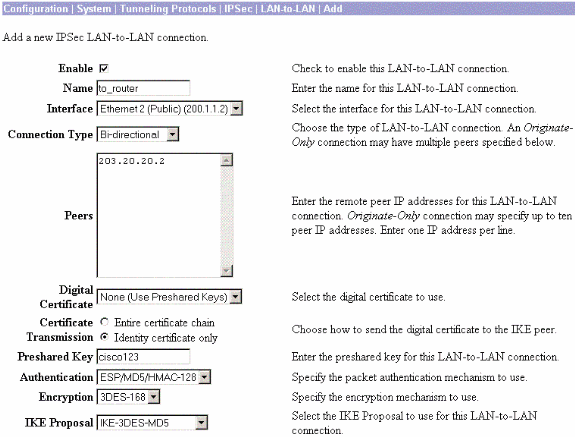
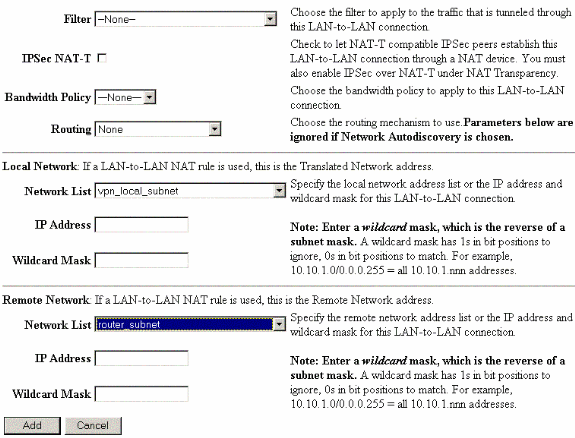
Choose Configuration > System > Tunneling Protocols > IPSec LAN-to-LAN and define the LAN-to-LAN tunnel.
-
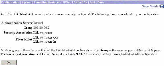
After you click Apply, this window is displayed with the other configuration that is automatically created as a result of the LAN-to-LAN tunnel configuration.
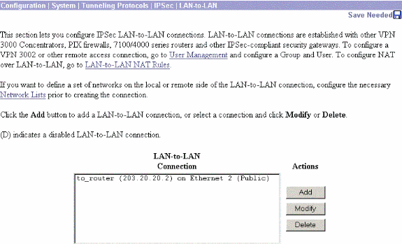
The previously created LAN-to-LAN IPsec parameters can be viewed or modified in Configuration > System > Tunneling Protocols > IPSec LAN-to-LAN.
-
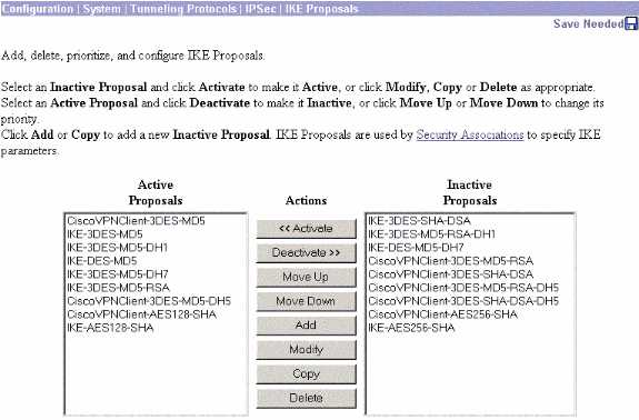
Choose Configuration > System > Tunneling Protocols > IPSec > IKE Proposals to confirm the active IKE Proposal.
-
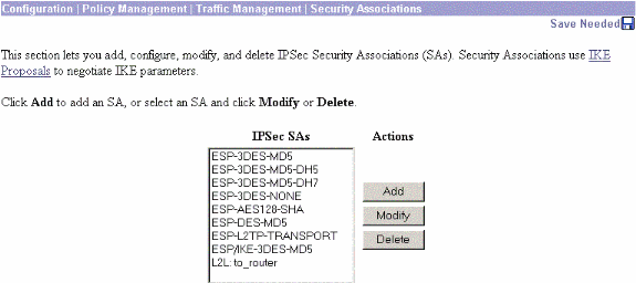
Choose Configuration > Policy Management > Traffic Management > Security Associations to view the list of Security Associations.
-
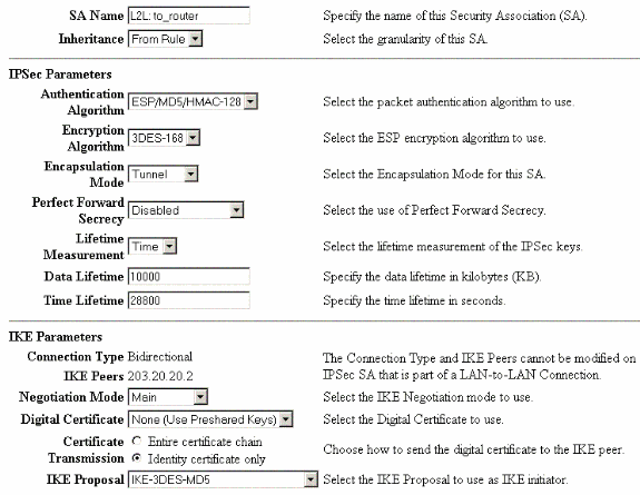
Click the Security Association name, and then click Modify to verify the Security Associations.
Verify
This section lists the show commands used in this configuration.
On the Router
This section provides information you can use to confirm your configuration works properly.
The Output Interpreter Tool (registered customers only) (OIT) supports certain show commands. Use the OIT to view an analysis of show command output.
-
show crypto ipsec sa—Shows the settings used by current Security Associations.
-
show crypto isakmp sa—Shows all current Internet Key Exchange Security Associations at a peer.
-
show crypto engine connection active—Shows the current active encrypted session connections for all crypto engines.
You can use the IOS Command Lookup Tool (registered customers only) to see more information about particular commands.
On the VPN Concentrator
Choose Configuration > System > Events > Classes > Modify to turn on logging. These options are available:
-
IKE
-
IKEDBG
-
IKEDECODE
-
IPSEC
-
IPSECDBG
-
IPSECDECODE
Severity to Log = 1-13
Severity to Console = 1-3
Select Monitoring > Event Log to retrieve the event log.
Troubleshoot
On the Router
Refer to Important Information on Debug Commands before you attempt any debug commands.
-
debug crypto engine—Displays the traffic that is encrypted.
-
debug crypto ipsec—Displays the IPsec negotiations of phase 2.
-
debug crypto isakmp—Displays the ISAKMP negotiations of phase 1.
Problem - Unable to Initiate the Tunnel
Error Message
20932 10/26/2007 14:37:45.430 SEV=3 AUTH/5 RPT=1863 10.19.187.229
Authentication rejected: Reason = Simultaneous logins exceeded for user
handle = 623, server = (none), user = 10.19.187.229, domain = <not
specified>
Solution
Complete this action in order to configure the desired number of simultaneous logins or set the simultaneous logins to 5 for this SA:
Go to Configuration > User Management > Groups > Modify 10.19.187.229 > General > Simultaneouts Logins and change the number of logins to 5.
PFS
In IPsec negotiations, Perfect Forward Secrecy (PFS) ensures that each new cryptographic key is unrelated to any previous key. Either enable or disable PFS on both the tunnel peers. Otherwise, the LAN-to-LAN (L2L) IPsec tunnel is not established in routers.
In order to specify that IPsec should ask for PFS when new Security Associations are requested for this crypto map entry, or that IPsec requires PFS when it receives requests for new Security Associations, use the set pfs command in crypto map configuration mode. In order to specify that IPsec should not request PFS, use the no form of this command.
set pfs [group1 | group2]
no set pfs
For the set pfs command:
-
group1 —Specifies that IPsec should use the 768-bit Diffie-Hellman prime modulus group when the new Diffie-Hellman exchange is performed.
-
group2 —Specifies that IPsec should use the 1024-bit Diffie-Hellman prime modulus group when the new Diffie-Hellman exchange is performed.
By default, PFS is not requested. If no group is specified with this command, group1 is used as the default.
Example:
Router(config)#crypto map map 10 ipsec-isakmp
Router(config-crypto-map)#set pfs group2
Refer to the Cisco IOS Security Command Reference for more information on the set pfs command.
Related Information
Revision History
| Revision | Publish Date | Comments |
|---|---|---|
1.0 |
24-Mar-2008 |
Initial Release |
Contact Cisco
- Open a Support Case

- (Requires a Cisco Service Contract)


 Feedback