Introduction
This document describes the recovery procedure of vEdge-5000 or ISR1100 series (ISR1100-4G/ISR1100-6G) routers in case if the device can not boot the operating system.
Problem
The device is unable to start. If you connect to console, you might see one of these messages on your screen:


You might also see that the device is booted to the Recovery Tool as shown in the image.

If you select Boot vEdge Software (Normal Boot) from the menu and the device is unbootable, you see:

Attempt to reboot, or hard reset by long-pressing the reset button with a sharp narrow tool will not help.
Solution
In order to recover the device, you need to prepare a bootable USB drive:
1. Format USB drive as MS-DOS (FAT32) file system.
2. Obtain a software image from the software.cisco.com and save it on your PC/laptop. Here, for example, vSmart, vEdge Cloud, vEdge 5000, ISR1100 series and vBond upgrade image viptela-19.2.2-x86_64.tar.gz are found here: https://software.cisco.com/download/home/286320995/type/286321394/release/19.2.2
3. Copyviptela-19.2.2-x86_64.tar.gz to the USB drive and rename to viptela-image-genericx86_64.tar.gz.
4. Create /EFI/BOOT/ directory on the USB drive.
5. Extract viptela-19.2.2-x86_64.tar.gz on your PC/laptop locally with any unarchiver. For example, use tar CLI utility:
$ tar -xvf viptela-19.2.2-x86_64.tar.gz
x md5sum
x rootfs.img
x rootfsimg.sig
x vmlinuz
x crash.kernel
x bootx64.efi
x sigs/
x sigs/3.sig
x sigs/1.sig
x sigs/2.sig
x sigs/5.sig
x sigs/4.sig
x sigs.vip
x image-signing.crt
x cisco_crl.pem
6. Copy vmlinuz file to the USB disk drive.
7. Copy bootx64.efi to the /EFI/BOOT/ disk.
Finally, the content of the USB disk must look like this:

8. Insert this boot drive into the USB slot of the vEdge-5000 or ISR1100 series router. It will be detected automatically.
9. If you see this menu when connected to device console, select Clean Install vEdge Software (From USB) as shown in the image.

And continue to Step number 14.
10. If you do not see the Recovery Tool menu, you need to specify USB in a boot order of the BIOS settings. Reboot the device and you see initialization prompt as shown in the image.

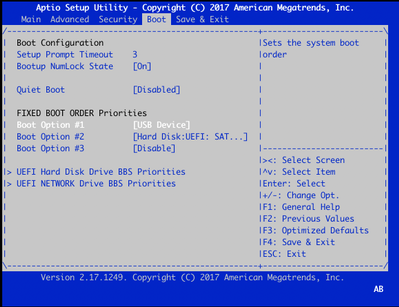
11. Press <DEL> or <ESC> button in order to enter to the BIOS, then navigate to Boot section of the menu with arrow keys on the keyboard and set [USB Device] as a first boot option as shown in the image.
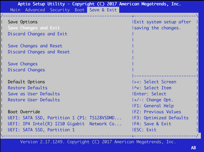
12. Then navigate to Save & Exit and select Save Changes and Exit from the menu with help of arrow keys and select enter as shown in the image.

13. You must see the Recovery Tool menu from Step 9.
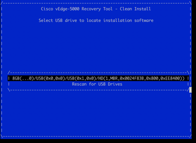
14. USB Drive is detected automatically if formatted properly and you will see a similar output as shown in the image.
15. If steps 1-8 are not completed successfully (e.g. wrong file system, incorrect file names are given or directory structures were made), you will see this:

Double-check if steps 1-8 were completed successfully and repeat the process. If you still experience any issues, contact Cisco TAC for assistance.
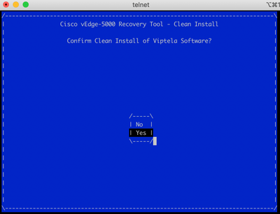
16. If Recovery Tool finds all required files on the USB drive, you see the next screen, select Yes as shown in the image in order to continue the installation.
The device attempts an installation process and reloads twice. Do not interrupt this process.
17. If the device is able to reinstall the software, you finally see a welcome prompt as shown in the image.

For ISR1100 this means that the device is recovered successfully and you can start the configuration from scratch. For vEdge-5000 check next section.
Extra steps to recover vEdge-5000
On vEdge-5000 it is also required to reset TPM chip. If this is not done, Board ID will be not initialized and vEdge-5000 won't be able to establish control connections. You may see output as below:
BRU-SDW-V5K-01# show control local-properties | i ^serial-num
serial-num BOARD-ID-NOT-INITIALISED
To fix this:
1. Connect to console and reboot the device to enter BIOS (press DEL or ESC key here):

2. You see BIOS screen. Select Advanced tab with arrow keys:

3. On Advanced tab, select Trusted Computing menu entry and press Enter key:

4. On appeared screen select Pending operation and press Enter key and select TPM Clear from the menu:

5. Next, press F4 to save settings or with help of arrow keys navigate to Save and Exit tab and select Save Changes and Exit from the menu.
6. Device is reloaded, repeat steps 1-3 to enter the BIOS and navigate to Advance tab again. Here enable TPM again as on the screenshot here by selecting TPM State from the menu and changing state to Enabled in the appeared menu:
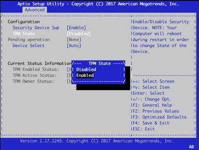
7. Repeat step 5 to save settings.
When device rebooted, recovery procedure is completed and TPM chip will be reinitialized and you can start the configuration from scratch.
