Introduction
This document describes a solution for addressing scaling issues in data center SD-WAN cEdges as they near their data plane tunnel limits.
Prerequisites
Requirements
Cisco recommends that you have knowledge of SD-WAN.
Components Used
The information in this document is based on these software and hardware versions:
The information in this document was created from the devices in a specific lab environment. All of the devices used in this document started with a cleared (default) configuration. If your network is live, ensure that you understand the potential impact of any command.
Background Information
Network Design Overview:
- VPN: VPN 10, VPN 20
- Transport links: Multiprotocol Label Switching (MPLS), LTE, Internet
- Router Detail:
- Primary Router: 2 in each Datacenter
- Model: ASR1002-HX
- Cisco IOS XE Software Version: 17.06.03a.0.2
- Secondary Router: 1 in each Datacenter
- Model: ISR4451-X
- Cisco IOS XE Software Version: 17.06.03a.0.22
- Routing protocol: Border Gateway Protocol (BGP) is used on Datacenter LAN side
Problem
This document discusses the customer case study having the topology shown, the network infrastructure of the customer comprises two data centers, each having two ASR1002-HX SD-WAN cEdge deployed. This network architecture aims to incorporate approximately 3000 store locations onto the SD-WAN overlay, leveraging the availability of three distinct transport links.

Note: Hub and Spoke topology is deployed. DC1 and DC2 cEdges are hubs. All remote branches form IPsec tunnels over three available transport with DC cEdges.
Exiting Network Diagram
All traffic from VPN 10 and VPN 20 traverses through MPLS transport.
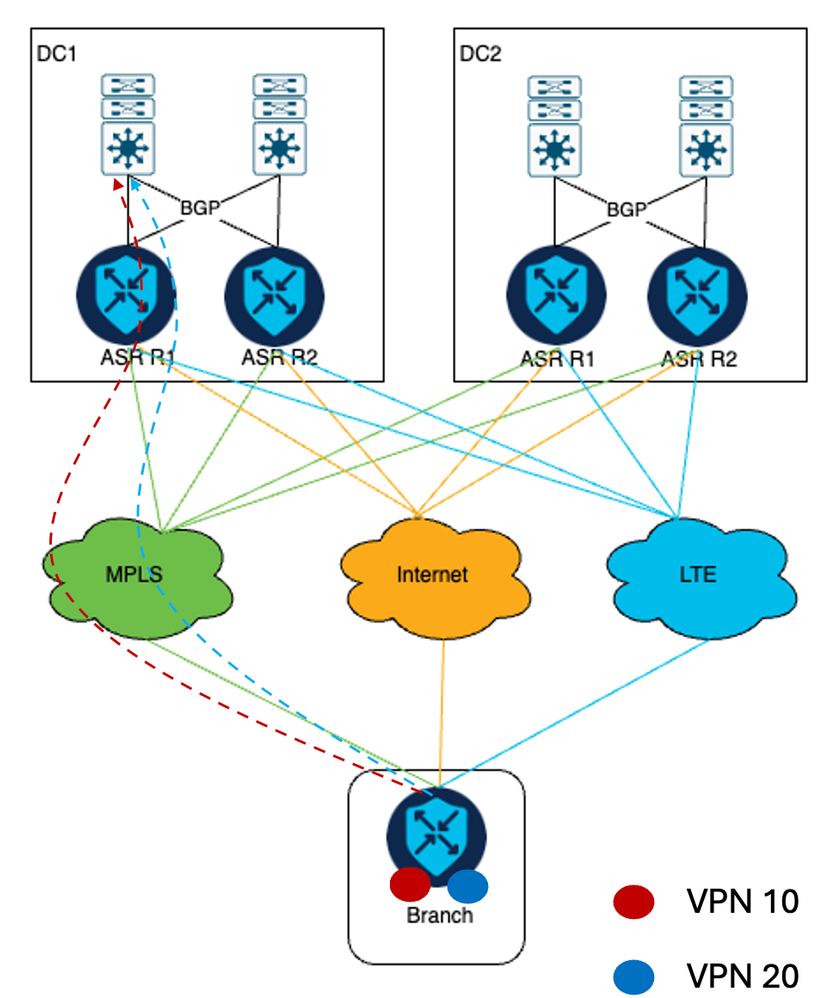
If the MPLS link goes down, VPN 10 traffic shifts to LTE transport, and VPN 20 traffic shifts to Internet transport.
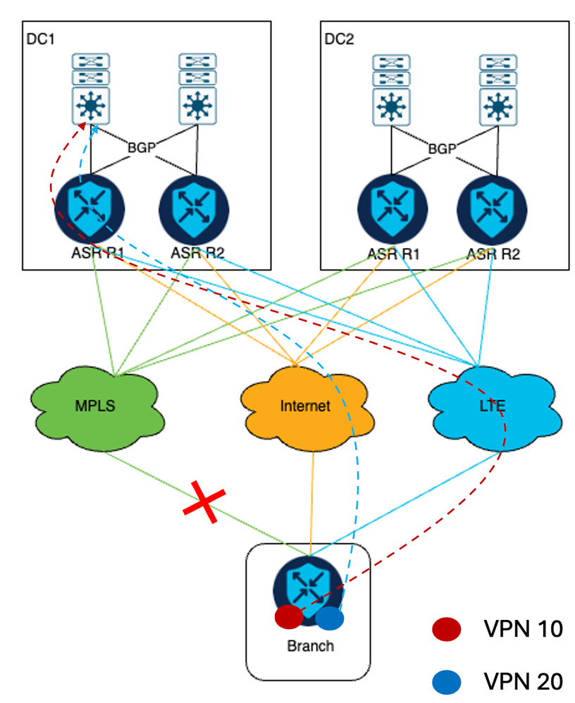
The technical challenge in this scenario arises from the scale and specific requirements of a network deployment of customers. Considering the deployment of 3000 SD-WAN routers establishing IPSec tunnels via three types of transport to the Data Center router, the total count of IPSec tunnels formed on ASR1002-HX primary headend routers reaches 9000. However, the ASR1002-HX is limited to 8000 IPSec tunnels (source: ASR1K Datasheet).
Solution
In order to solve this, the customer decided to add an ISR4451-X cEdge device in each DC as per the future scalability requirement of the customer.

Note: Decide an additional device model based on the scalability requirement of the customer.
Network Topology
As part of the solution, primary Aggregation Services Router (ASR) cEdges continue to form an IPSec tunnel over MPLS and internet transport, and newly installed Integrated Service Router (ISR) cEdges form an IPsec tunnel only via LTE transport.
As depicted in the diagram, IPSec tunnels are established between the ASR headend and the branch via both MPLS and the internet, while between the ISR and the branch, IPSec tunnels are established solely via LTE.
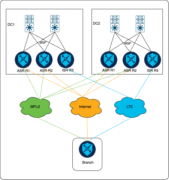
The customer requirement is that, under normal circumstances, all VPN 10 and VPN 20 traffic utilize MPLS transport for communication. However, in the event of an MPLS link failure, VPN 20 traffic is rerouted through internet transport, while VPN 10 traffic is redirected through LTE transport, behavior as before adding additional cEdge.
Configure
Centralized and localized policies are used in order to ensure traffic is sent out via the correct transport per the preference of the customer. Traffic coming in from the branch location via the internet link and LTE link is tagged. These tags are used to ensure that LAN switches on the headend send out reply messages for VPN 10 correctly to the ISR router and that VPN 20 traffic is sent out to ASR headend devices.
Centralized Policy Configuration
Here is the policy prepared in order to meet customer requirements. For traffic arriving via the internet link, an OMP tag of 200 is assigned. On the other hand, traffic arriving through the LTE link is assigned an OMP tag of 100.
Centralized Policy

control-policy DataCenter_Outbound_v001
<<omited>>
  sequence 10
   match route
    color-list MPLS
    site-list remote_branches
  vpn-list vpn-10
    prefix-list _AnyIpv4PrefixList
  !
   action accept
    set
     preference 1500
 !
 !
 sequence 20
    match route
      color-list LTE
      site-list remote_branches
      vpn-list vpn-10
      prefix-list _AnyIpv4PrefixList
    !
    action accept
     set
      preference 1000
      omp-tag 100
    !
   !
  !
  sequence 30
    match route
      color-list Internet
      site-list remote_branches
      vpn-list vpn-10
      prefix-list _AnyIpv4PrefixList
    !
    action accept
     set
      preference 500
      omp-tag 200
     !
    !
  !
  sequence 40
   match route
    color-list MPLS
    site-list remote_branches
    vpn-list vpn-20
    prefix-list _AnyIpv4PrefixList
   !
   action accept
    set
     preference 1500
   !
  sequence 50
    match route
      color-list LTE
      site-list remote_branches
      vpn-list vpn-20
      prefix-list _AnyIpv4PrefixList
    !
    action accept
     set
      preference 500
      omp-tag 100
     !
    !
  !
  sequence 60
    match route
      color-list Internet
      site-list remote_branches
      vpn-list vpn-20
      prefix-list _AnyIpv4PrefixList
    !
    action accept
     set
      preference 1000
      omp-tag 200
    !
   !
  !
<<omited>>
site-list remote_branches
site-id <specifiy site-id range for all remote branch sites>
At DC, while forwarding traffic from SD-WAN routers to core switches, the AS-PATH field is manipulated when advertising the route into BGP on the LAN side. A route map is applied in the BGP configuration at the time of redistribution of OMP routes in BGP.
When the MPLS link is operational, only the primary cEdges redistribute routes in BGP as no traffic is received via LTE. However, in the event of an MPLS link failure:
-
For VPN 10, the ASR cEdges redistribute routes by appending the AS-PATH field four times, while the ISR cEdge redistributes by appending the AS-PATH field three times. This configuration ensures that the ISR cEdge is preferred for sending replies.
-
Similarly, for VPN 20, the ASR cEdges redistribute prefixes without appending any AS-PATH, and the ISR cEdge redistributes prefixes by appending the AS-PATH field three times. This ensures that the ASR cEdges are preferred.
Localized Policy Configuration
route-map DC1_Primary_VPN-10_out_v001 permit 1
match omp-tag 200
set as-prepend <dc1-asnum> <dc1-asnum> <dc1-asnum> <dc1-asnum>
route-map DC1_VPN-10_out_v001 permit 65535

route-map DC2_Primary_VPN-10_out_v001 permit 1
match omp-tag 200
set as-prepend <dc2-asnum> <dc2-asnum> <dc2-asnum> <dc2-asnum>
route-map DC2_VPN-10_out_v001 permit 65535

route-map DC1_Backup_All_out_v001 permit 1
match omp-tag 100
set as-prepend <dc1-asnum> <dc1-asnum> <dc1-asnum>
route-map DC1_Backup_All_out_v001 deny 65535

route-map DC2_Backup_All_out_v001 permit 1
match omp-tag 100
set as-prepend <dc2-asnum> <dc2-asnum> <dc2-asnum>
route-map DC2_Backup_All_out_v001 deny 65535
Traffic Flow
Normal Scenario
When the MPLS link is up, all traffic from VPN 10 and VPN 20 traverses through the MPLS transport.
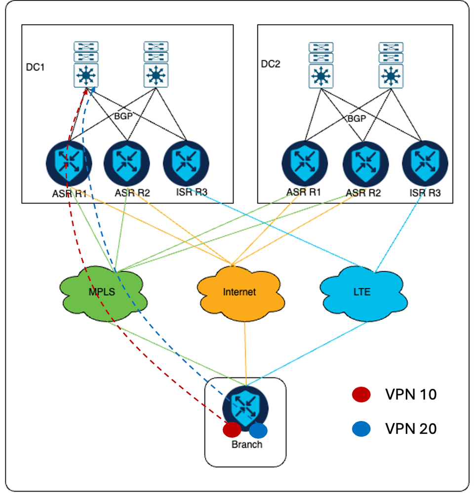

Note: DC1 is the primary DC.
Failover Scenario
In the event of MPLS link failure, VPN 10 traffic traverses via LTE transport towards ISR cEdge. Where as VPN 20 traffic is sent via Internet transport to ASR cEdge device.
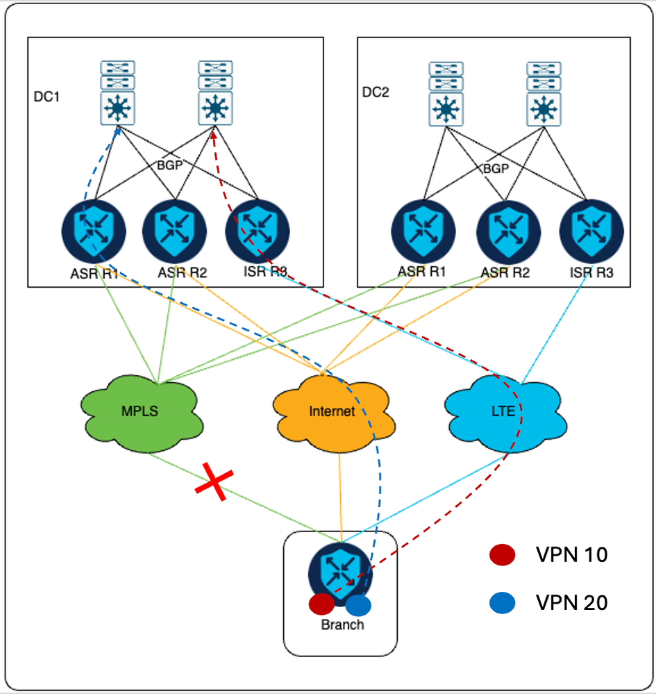
For return traffic from core switches, for VPN 10 traffic is sent to the ISR cEdge as the AS-PATH length is smaller via ISR compared to ASR as specified in the localized policy section. Similarly, VPN 20 traffic is sent towards ASR cEdges as AS-PATH is smaller via ASR compared to ISR.
Additional Information
In the earlier setup, all cEdges at each DC are connected to SD-WAN controllers only via Internet transport. Thus ISR routers have Internet tunnel configured. The requirement is to ensure that ISR cEdge forms an IPsec tunnel to remote branches only via LTE transport and in order to achieve the given requirement, the tunnel color on internet transport of ISR must be configured with a public color that is not in use in customer setup.


 Feedback