ASR 9000 nV decluster procedure
Available Languages
Download Options
Bias-Free Language
The documentation set for this product strives to use bias-free language. For the purposes of this documentation set, bias-free is defined as language that does not imply discrimination based on age, disability, gender, racial identity, ethnic identity, sexual orientation, socioeconomic status, and intersectionality. Exceptions may be present in the documentation due to language that is hardcoded in the user interfaces of the product software, language used based on RFP documentation, or language that is used by a referenced third-party product. Learn more about how Cisco is using Inclusive Language.
Contents
Introduction
This document describes some of the nV cluster features of the ASR 9000 and how to decluster.
The procedure was tested in real environment with Cisco customers who have already decided for the declustering process explained in this document.
Prerequisites
Requirements
Cisco recommends that you have knowledge of these topics:
- IOS XR
- ASR 9000 platform
- nV cluster feature
Components Used
The information in this document is based onASR 9000 platform running IOS XR 5.x.
The information in this document was created from the devices in a specific lab environment. All of the devices used in this document started with a cleared (default) configuration. If your network is live, ensure that you understand the potential impact of any command.
Background Information
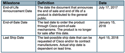
Product Business Unit (BU) announced End-of-Sale (EOS) for nV Cluster on the ASR 9000 platform: End-of-Sale and End-of-Life Announcement for the Cisco nV Cluster
As you can read in the announcement, the last day to order this product is January 15, 2018, and the last supported release for nV cluster is IOS-XR 5.3.x.
Milestones to be aware of are listed in this table:
ASR9k nV Cluster Fundamentals & Considerations
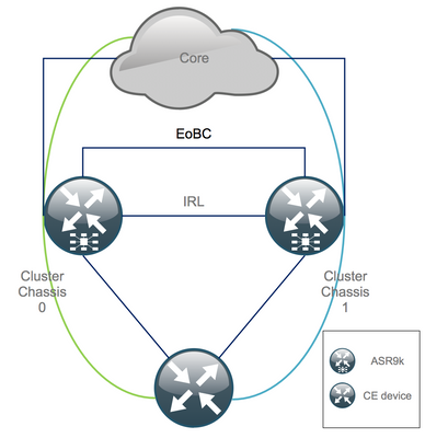
The goal of this section is to provide a brief refresh on cluster setups and concepts necessary to understand the next sections of this document.
Ethernet Out of Band Channel (EOBC)
The Ethernet Out of Band channel extends the control plane between the two ASR9k chassis and ideally consists of 4 interconnects that build a mesh between Route Switch Processor (RSP) of different chassis. This setup provides additional redundancy in case of EOBC link failure. Unidirectional Link Detection Protocol (UDLD) ensures bi-directional data forwarding and quickly detects link failures. Malfunction of all EOBC links seriously affects the cluster system and can have serious consequences that are presented later in the section Split Node Scenarios.
Inter Rack Links (IRL)
The Inter Rack Links extend the data plane between the two ASR9k chassis. Ideally, only protocol punt and protocol injects packets go across the IRL, except for single-homed services, or during network failures. In theory, all end-systems are dual-homed with a link to both ASR9K chassis. Similar to the EOBC links, UDLD runs on top of the IRL as well to monitor bi-directional forwarding health of the links.
An IRL threshold can be defined to prevent congested IRL from dropping packets in the case of LC failure, for instance. If the number of IRL links fall below the configured threshold for that chassis, all interfaces of the chassis are error-disabled and shut down. This basically isolates the affected chassis and makes sure that all traffic flows through the other chassis.
Note: The default configuration is equivalent to nv edge data minimum 1 backup-rack-interfaces which means that if no IRL is in the forwarding state the backup Designated Shelf Controller (DSC) is isolated.
Split Node Scenarios
In this subsection you can find the different failure scenarios that can be encountered when dealing with ASR9k clusters:
IRL Down
This is the only Split Node scenario which can be expected during declustering, or if one of the chassis falls below the IRL threshold and becomes isolated as a consequence.
EOBC Down
The two chassis of the ASR9k cannot act as one without the extended control-plane provided by the EOBC links. There are periodic beacons that are exchanged over the IRL links so each chassis is aware that the other chassis is up. As a consequence, one of the chassis, usually the chassis with the Backup-DSC, takes itself out of service and reboots. The Backup-DSC chassis remains in the boot loop as long as it receives the beacons of the Primary-DSC chassis over the IRL.
Split Brain
In the Split Brain scenario IRL and EOBC links have gone down and each chassis declares itself as Primary-DSC. Neighboring network devices suddenly see duplicate Router IDs for IGP and BGP which can cause severe issues in the network.
Bundles
Many customers make use of Bundles on the Edge and Core side to simplify the ASR9K cluster setup and to facilitate bandwidth increases in the future. This could cause issues when declustering due to different Bundle members connecting to different chassis. These approaches are possible:
- Create new Bundles for all interfaces connected to Chassis 1 (Backup-DSC).
- Introduce Multichassis Link Aggregation (MCLAG).
L2 Domain
Splitting up the cluster could potentially separate the L2 domain, if there is no switch in the access that interconnects the two stand-alone chassis. In order not to black hole traffic, you need to extend the L2 domain which can be done if you configure L2 local-connects on the previous IRL, Pseudo-Wires (PW) between the chassis, or make use of any other Layer 2 Virtual Private Network (L2VPN) technology. As the bridge domain topology changes with declustering, mind the possible loop creation when you select the L2VPN technology of choice.
Static routing in the access towards a bridge-group virtual interface (BVI) interface on the ASR9K cluster is likely to turn into an Hot Standby Router Protocol (HSRP)-based solution using the previous BVI IP address as virtual IP.
Single-Homed Services
Single-Homed services have an extended down time during the declustering procedure.
Management Access
During the declustering process, there is a short time where both chassis are isolated, at least when transitioning from static routing (BVI) to static routing (HSRP) in order not to have unexpected and asymmetric routing.
You must verify how the console and Out of Band management access work, before to lock yourself out.
ASR9000 declustering procedure
The Initial State
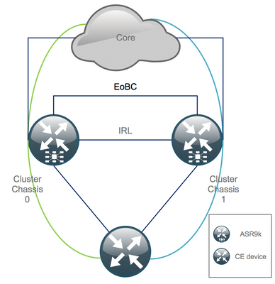
Assume that in the initial state chassis 0 is active, whilst chassis 1 is backup (for the sake of simplicity). In real life it could be the other way around or even RSP1 in chassis 0 could be active.
Check-List Before the Maintenance Window (MW)
- Prepare the new ASR9K chassis 0 and chassis 1 configurations (Admin-Config + Config).
- Prepare the new end system configurations (Customer Edge (CE), Firewall (FW), Switches, etc.).
- Prepare the new core system configurations (P-nodes, Provider Edge (PE) nodes, Route Reflector (RR), etc.).
- Verify the new configurations, store it on the device and remotely on a Trivial File Transfer Protocol (TFTP) server.
- Define reachability tests which must be run before/during/after the MW.
- Collect control-plane outputs for Interior Gateway Protocol (IGP), Border Gateway Protocol (BGP), Multiprotocol Label Switching (MPLS), Label Distribution Protocol (LDP), etc. for before/after comparison.
- Open a pro-active service request with Cisco.
Step 1. Log In Into the ASR9000 Cluster and Verify the Current Configuration
1. Verify the location of Primary – Backup chassis. In this example, the Primary chassis is 0:
RP/0/RSP0/CPU0:Cluster(admin)# show dsc

---------------------------------------------------------

   Node        (     Seq)     Role     Serial# State

---------------------------------------------------------

   0/RSP0/CPU0 ( 1279475)   ACTIVE FOX1441GPND PRIMARY-DSC <<< Primary DSC in Ch1

   0/RSP1/CPU0 ( 1223769)  STANDBY FOX1432GU2Z NON-DSC

   1/RSP0/CPU0 (       0)   ACTIVE FOX1432GU2Z BACKUP-DSC

   1/RSP1/CPU0 ( 1279584)  STANDBY FOX1441GPND NON-DSC
2. Verify that all Line Cards (LC)/RSPs are in “IOS XR RUN” state:
RP/0/RSP0/CPU0:Cluster# sh platform
Node            Type                      State            Config State
-----------------------------------------------------------------------------
0/RSP0/CPU0     A9K-RSP440-TR(Active)     IOS XR RUN       PWR,NSHUT,MON
0/RSP1/CPU0     A9K-RSP440-TR(Standby)    IOS XR RUN       PWR,NSHUT,MON
0/0/CPU0        A9K-MOD80-SE              IOS XR RUN       PWR,NSHUT,MON
0/0/0           A9K-MPA-4X10GE            OK               PWR,NSHUT,MON
0/0/1           A9K-MPA-20X1GE            OK               PWR,NSHUT,MON
0/1/CPU0        A9K-MOD80-TR              IOS XR RUN       PWR,NSHUT,MON
0/1/0           A9K-MPA-20X1GE            OK               PWR,NSHUT,MON
0/2/CPU0        A9K-40GE-E                IOS XR RUN       PWR,NSHUT,MON
1/RSP0/CPU0     A9K-RSP440-TR(Active)     IOS XR RUN       PWR,NSHUT,MON
1/RSP1/CPU0     A9K-RSP440-SE(Standby)    IOS XR RUN       PWR,NSHUT,MON
1/1/CPU0        A9K-MOD80-SE              IOS XR RUN       PWR,NSHUT,MON
1/1/1           A9K-MPA-2X10GE            OK               PWR,NSHUT,MON
1/2/CPU0        A9K-MOD80-SE              IOS XR RUN       PWR,NSHUT,MON
1/2/0           A9K-MPA-20X1GE            OK               PWR,NSHUT,MON
1/2/1           A9K-MPA-4X10GE            OK               PWR,NSHUT,MON
Step 2. Configure Minimum IRL Threshold for the Standby Chassis
The standby chassis is the chassis with the BACKUP-DSC and is taken out of service and declustered first. In this example, the BACKUP-DSC is located in chassis 1.
With this configuration, if the number of IRLs falls below the minimum threshold configured (1 in this case), all interfaces on the specified rack (backup rack – chassis 1 in this case) is shut down:
RP/0/RSP0/CPU0:Cluster(admin-config)# nv edge data min 1 spec rack 1
RP/0/RSP0/CPU0:Cluster(admin-config)# commit
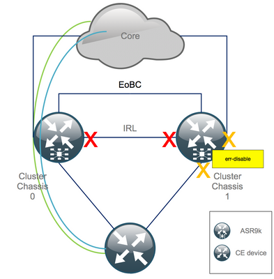
Step 3. Shut Down All IRL and Verify Error-Disable Interfaces on Chassis 1
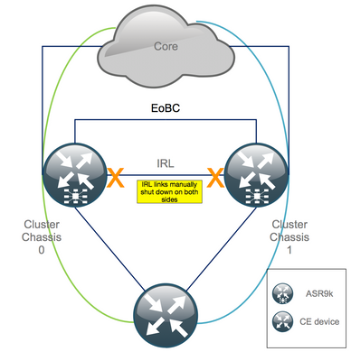
1. Shut all existing IRL. In this example, you can see a manual interface shutdown in both chassis (active Ten0/x/x/x and standby Ten1/x/x/x):
RP/0/RSP0/CPU0:Cluster(config)#

interface Ten0/x/x/x
shut
interface Ten0/x/x/x
 shut
[…]
interface Ten1/x/x/x
 shut
interface Ten1/x/x/x
shut
[…]

commit
2. Verify that all configured IRL are down:
RP/0/RSP0/CPU0:Cluster# show nv edge data forwarding location <Location>
An example of <location> is 0/RSP0/CPU0.
After a shut-down of all IRL, chassis 1 must be fully isolated from the data plane by moving all external interfaces to the error-disabled state.
3. Verify that all external interfaces on chassis 1 are in the err-disabled state and that all traffic flows through chassis 0:
RP/0/RSP0/CPU0:Cluster# show error-disable
Step 4. Shut Down All EOBC Links and Verify Their Status
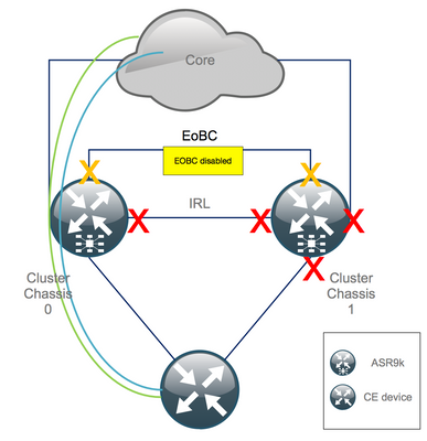
1. Shut EOBC links on all RSPs:
RP/0/RSP0/CPU0:Cluster(admin-config)#
nv edge control control-link disable 0 loc 0/RSP0/CPU0
nv edge control control-link disable 1 loc 0/RSP0/CPU0
nv edge control control-link disable 0 loc 1/RSP0/CPU0
nv edge control control-link disable 1 loc 1/RSP0/CPU0
nv edge control control-link disable 0 loc 0/RSP1/CPU0
nv edge control control-link disable 1 loc 0/RSP1/CPU0
nv edge control control-link disable 0 loc 1/RSP1/CPU0
nv edge control control-link disable 1 loc 1/RSP1/CPU0
commit
2. Verify that all EOBC links are down:
RP/0/RSP0/CPU0:Cluster#
show nv edge control control-link-protocols location 0/RSP0/CPU0
After this step, the Cluster Chassis are fully isolated from each other in terms of control – and data plane. Chassis 1 has all its links in the err-disable state.
Note: From now on, configurations have to be done on chassis 1 through the RSP console and only affect the local chassis!
Step 5. Log In Into the Active RSP of Chassis 1 and Remove Old Configuration
Clear the existing configuration on chassis 1:
RP/1/RSP0/CPU0:Cluster(config)# commit replace
RP/1/RSP0/CPU0:Cluster(admin-config)# commit replace
Note: You need to replace first the configuration for the running-configuration and only afterwards clear the admin running-configuration. This is due to the fact that removing the IRL threshold in the admin running-configuration does “no shut” all external interfaces. This could cause issues due to duplicate router IDs, etc.
Step 6. Boot Chassis 1 Into ROMMON mode
1. Set configuration register to boot into ROMMON:
RP/1/RSP0/CPU0:Cluster(admin)# config-register boot-mode rom-monitor location all
2. Verify the boot variables:
RP/1/RSP0/CPU0:Cluster(admin)# show variables boot
3. Reload both RSPs of chassis 1:
RP/1/RSP0/CPU0:Cluster# admin reload location all
After this step, normally, chassis 1 boots into ROMMON.
Step 7. Unset CLuster Variables on Chassis 1 in ROMMON on Both RSPs
Warning: Field technician must remove all EOBC links before moving on.
Tip: There is also an alternative to set system cluster variables. Check section Appendix 2: Set Cluster variable without booting the system into rommon.
1. The standard procedure requires to connect the console cable to the active RSP on chassis 1, and unset and sync Cluster ROMMON variable:
unset CLUSTER_RACK_ID
sync
2. Reset the configuration registers to 0x102:
confreg 0x102
reset
The active RSP is set.
3. Connect the console cable to the standby RSP of chassis 1. Ideally, all 4 RSPs of the cluster have console access during the maintenance window.
Note: The actions described in this step need to be done on both RSPs of chassis 1. The active RSP must be booted first.
Step 8. Boot Chassis 1 as a Stand-Alone System and Configure It Accordingly
Ideally, the new configuration or several configuration snippets is stored on each ASR9k chassis and loaded after the declustering. The correct configuration syntax must be tested in the lab previously. If not, configure console and MGMT interfaces first, before completing the configuration on chassis 1 either through copy and paste on Virtual Teletype (VTY) or load the config remotely from a TFTP server.
Note: the commands load config and commit keep all interfaces shutdown, which allows for a controlled service ramp-up. load config and commit replace, fully replaces the configuration and brings up the interfaces. Therefore, it is recommended to use the load config and commit.
Adapt the configuration of connected end-systems (FW, Switches, etc) and core devices (P, PE, RR, etc) to chassis 1.
Step 9. Restore Core Services on Chassis 1
- Manually un-shut core interfaces first.
- Verify LDP, Intermediate System to Intermediate System (IS-IS or ISIS), BGP adjacencies/peerings.
- Verify the routing tables and ensure that all prefixes have been exchanged.
Warning: Beware of timers such as ISIS Overload (OL) bit, HSRP delay, BGP Update delay, etc. before moving on to the failover!
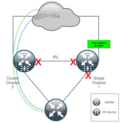
Step 10. Failover - Log In Into the Active RSP of Chassis 0 and Bring All Interfaces Into Error-Disable State
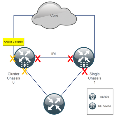
Caution: The next steps cause service disruption. Chassis 1 southbound interfaces are still disabled, whilst chassis 0 is isolated
The default hold-time equals 180s (3x60s) and represents the worst case for BGP convergence. There are several design options and BGP features that allow for much faster convergence time, such as BGP Next-Hop Tracking. Assume that there are different 3rd party vendors present in the core that behave differentely than Cisco IOS XR, you eventually need to speed up BGP convergence manually with a software shut of the BGP neighborships between chassis 0 and the RR, or similar, before you trigger the failover:
RP/0/RSP0/CPU0:Cluster(admin-config)# nv edge data minimum 1 specific rack 0
RP/0/RSP0/CPU0:Cluster(admin-config)# commit
Since all IRL are down, chassis 0 must be isolated and all external interfaces moved into the error-disabled state.
Verify that all external interfaces on chassis 0 are in the err-disabled state:
RP/0/RSP0/CPU0:Cluster# show error-disable
Chassis 1 has been reconfigured as a stand alone box so there must not be any err-disabled interfaces. The only thing left to do on chassis 1 is to bring up the interfaces on the edge.
Step 11. Restore South-Side on Chassis 1
1. no shut all access interfaces.
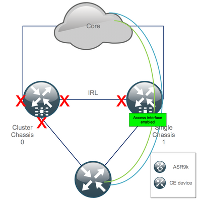
Keep the interconnect link (previous IRL) in shutdown for now.
2. Verify IGP and BGP adjacencies/peerings/DB. While the IGPs and BGP converge, you expect to see some traffic loss on you pings from the remote PE.
Step 12. Log In Into the Active RSP of Chassis 0 and Remove Configuration
Clear the existing configuration on active chassis:
RP/0/RSP0/CPU0:Cluster(config)# commit replace
RP/0/RSP0/CPU0:Cluster(admin-config)# commit replace
Note: you must first replace the configuration for the running-configuration and only afterwards clear the admin running-configuration. This is due to the fact that removing the IRL threshold in the admin running-configuration does no shut all external interfaces. This could cause issues due to duplicate router IDs, etc.
Step 13. Boot Chassis 0 Into ROMMON
1. Set configuration register to boot into ROMMON:
RP/0/RSP0/CPU0:Cluster(admin)# config-register boot-mode rom-monitor location all
2. Verify the boot variables:
RP/0/RSP0/CPU0:Cluster# admin show variables boot
3. Reload both RSPs of Standby Chassis:
RP/0/RSP0/CPU0:Cluster# admin reload location all
After this step, normally, chassis 0 boots into the ROMMON mode.
Step 14. Unset Cluster Variables on Chassis 0 in ROMMON on Both RSPs
1. Connect the console cable to the active RSP on chassis 0.
2. Unset and sync Cluster ROMMON variable:
unset CLUSTER_RACK_ID
sync
3. Reset the configuration registers to 0x102:
confreg 0x102
reset
The active RSP is set.
4. Connect the console cable to the standby RSP on chassis 0.
Note: The actions described in this step need to be done on both RSPs of chassis 1. The active RSP must be booted first.
Step 15. Boot Chassis 0 as a Stand-Alone system and COnfigure It Accordingly
Ideally, the new configuration or several configuration snippets are stored on each ASR9k chassis and loaded after the declustering. The correct configuration syntax must be tested in the lab previously. If not, configure console and MGMT interfaces first, before completing the configuration on chassis 0 either through VTY (Copy & Paste) or load the config remotely from a TFTP server.
Note: the commands load config and commit keep all interfaces shutdown, which allows for a controlled service ramp-up. load config and commit replace, fully replaces the configuration and brings up the interfaces. Therefore, it is recommended to use the load config and commit.
Adapt the configuration of connected end-systems (FW, Switches, etc) and core devices (P, PE, RR, etc) to chassis 0.
Step 16. Restore Core Services on Chassis 0
- Manually un-shut core interfaces first.
- Verify LDP, ISIS, BGP adjacencies/peerings.
- Verify that routing tables and ensure that all prefixes have been exchanged.
Warning: Beware of timers such as ISIS OL-Bit, HSRP delay, BGP Update delay, etc. before moving on to the failover!
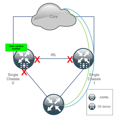
Step 17. Restore South-Side on Chassis 0
1. no shut all access interfaces.
2. Verify IGP and BGP adjacencies/peerings/DB
3. Ensure that Inter Chassis link (previous IRL) is enabled, if needed for L2 extension, etc.
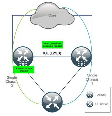
Appendix 1: Single Chassis Configuration
General Configuration Changes
This router configuration needs to be modified on one of the chassis:
- Loopback Interface Addresses.
- Interface numbering (e.g. Te1/x/x/x -> Te0/x/x/x).
- Interface descriptions.
- Interface addressing (when splitting up existing bundles).
- New BVIs (when L2 domain is dual-homed).
- L2 extension (when L2 domain is dual-homed).
- HSRP for static routing in access.
- BGP/Open Shortest Path First (OSPF)/LDP Router ID.
- BGP Route-Distinguishers.
- BGP Peerings.
- OSPF network type.
- Simple Network Management Protocol (SNMP) IDs, etc.
- Access Control List (ACL), Prefix-Sets, Routing Protocol for LLN (Low-Power and Lossy Networks) (RPL), etc.
- Hostname.
Bundle Overview
Ensure all bundles are reviewed and applied to the new dual PE setup. Perhaps you do not need bundles anymore and dual homed customer-premises equipment (CPE) devices fit your setup or you need MCLAG on PE devices and keep bundles towards CPEs.
Appendix 2: Set Cluster Variable Without Booting the System into ROMMON
There is also an alternative for setting the cluster variables. Cluster variables can be set upfront using this procedure:
RP/0/RSP0/CPU0:xr#run
Wed Jul  5 10:19:32.067 CEST

# cd /nvram:

# ls
cepki_key_db               classic-rommon-var         powerup_info.puf           sam_db                     spm_db
classic-public-config      license_opid.puf           redfs_ocb_force_sync       samlog                     sysmgr.log.timeout.Z

# more classic-rommon-var
  PS1 = rommon ! > , IOX_ADMIN_CONFIG_FILE = , ACTIVE_FCD = 1, TFTP_TIMEOUT = 6000, TFTP_CHECKSUM = 1, TFTP_MGMT_INTF = 1, TFTP_MGMT_BLKSIZE = 1400, TURBOBOOT = , ? =
0, DEFAULT_GATEWAY = 127.1.1.0, IP_SUBNET_MASK = 255.0.0.0, IP_ADDRESS = 127.0.1.0, TFTP_SERVER = 127.1.1.0, CLUSTER_0_DISABLE = 0, CLUSTERSABLE = 0, CLUSTER_1_DISABLE
 = 0, TFTP_FILE = disk0:asr9k-os-mbi-5.3.4/0x100000/mbiasr9k-rp.vm, BSS = 4097, BSI = 0, BOOT = disk0:asr9k-os-mbi-6.1.3/0x100000/mbiasr9k-rp.vm,1;, CLUSTER_NO_BOOT =
, BOOT_DEV_SEQ_CONF = , BOOT_DEV_SEQ_OPER = , CLUSTER_RACK_ID = 1, TFTP_RETRY_COUNT = 4, confreg = 0x2102

# nvram_rommonvar CLUSTER_RACK_ID 0   <<<<<<< to set CLUSTER_RACK_ID=0

# more classic-rommon-var
  PS1 = rommon ! > , IOX_ADMIN_CONFIG_FILE = , ACTIVE_FCD = 1, TFTP_TIMEOUT = 6000, TFTP_CHECKSUM = 1, TFTP_MGMT_INTF = 1, TFTP_MGMT_BLKSIZE = 1400, TURBOBOOT = , ? =
0, DEFAULT_GATEWAY = 127.1.1.0, IP_SUBNET_MASK = 255.0.0.0, IP_ADDRESS = 127.0.1.0, TFTP_SERVER = 127.1.1.0, CLUSTER_0_DISABLE = 0, CLUSTERSABLE = 0, CLUSTER_1_DISABLE
 = 0, TFTP_FILE = disk0:asr9k-os-mbi-5.3.4/0x100000/mbiasr9k-rp.vm, BSS = 4097, BSI = 0, BOOT = disk0:asr9k-os-mbi-6.1.3/0x100000/mbiasr9k-rp.vm,1;, CLUSTER_NO_BOOT =
, BOOT_DEV_SEQ_CONF = , BOOT_DEV_SEQ_OPER = , TFTP_RETRY_COUNT = 4, CLUSTER_RACK_ID = 0, confreg = 0x2102

#exit
RP/0/RSP0/CPU0:xr#
Reload the router and it boots it as a standalone box. With this step, you can skip to boot the router from ROMMON.
Revision History
| Revision | Publish Date | Comments |
|---|---|---|
1.0 |
05-Apr-2019 |
Initial Release |
Contributed by
- Robert VerlicAdvanced Services
Contact Cisco
- Open a Support Case

- (Requires a Cisco Service Contract)
 Feedback