Introduction
This document describes how to migrate two Cisco Aggregation Services Router (ASR) 9000 (9K) single-chassis systems to a Network Virtualization (nV) Edge system.
Prerequisites
Requirements
In order to cluster two routers together, there are several requirements that must be met.
Software
You must have Cisco IOS® XR Release 4.2.1 or later.
Note: nV Edge software is integrated into the mini package.
Hardware
Chassis:
- ASR 9006 and 9010 that started in Release 4.2.1
- ASR 9001 support that started in Release 4.3.0
- ASR 9001-S and 9922 support that started in Release 4.3.1
- ASR 9904 and 9912 support that started in Release 5.1.1
Note: Identical chassis types must be used for nV Edge.
Line Card (LC) and Route Switch Processor (RSP):
- Dual RSP440 for 9006/9010/9904
- Dual Route Processor (RP) for 9912/9922
- Single RSP for 9001/9001-S
- Typhoon-based LC or SPA Interface Processor (SIP)-700
Note: RSP-4G, RSP-8G, Trident-based LCs, Integrated Service Module (ISM), and Virtualized Services Module (VSM) are not supported
Note: Only Typhoon-based LCs can support Inter-Rack Link (IRL) links.
Control Links (Ethernet Out of Band Control (EOBC)/Cluster ports) supported optics:
- Small Form-Factor Pluggabble (SFP)-GE-S, Release 4.2.1
- GLC-SX-MMD, Release 4.3.0
- GLC-LH-SMD, Release 4.3.0
Data Links / IRL supported optics:
- Optics support is as per LC support
- 10G IRL support that started in Release 4.2.1
- 40G IRL support that started in Release 5.1.1
- 100G IRL support that started in Release 5.1.1
Note: There is no 1G IRL support.
Note: See the Cisco ASR 9000 Transceiver Modules - Line Card Support Data Sheet for LC optics support.
Note: IRL mixed-mode is not supported; all IRLs must be the same speed.
Components Used
The example in this document is based upon two 9006 routers with an RSP440 that run XR Release 4.2.3.
The information in this document was created from the devices in a specific lab environment. All of the devices used in this document started with a cleared (default) configuration. If your network is live, make sure that you understand the potential impact of any command.
Example Migration
Terminology
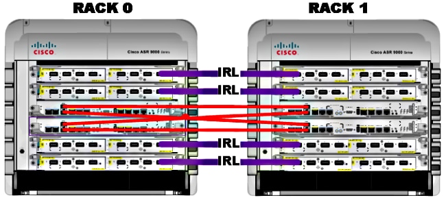
The IRLs are the data plane connection between the two routers in the cluster.
The control link or EOBC ports are the control plane connection between the two routers.
Network Diagram

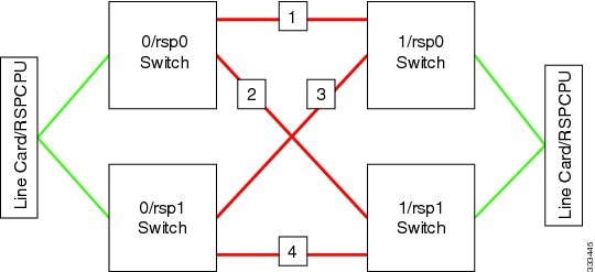
Note: The Control links are cross-connected as shown here.

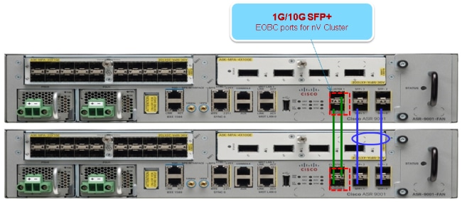
For the 9001, there are two cluster ports (pictured in green) that act as the 10G EOBC links. Any 10G port can be used for for IRL links including the on-board SFP+ ports (pictured in blue) or a 10G port in a Modular Port Adapter (MPA).

Migration
Note: Do not cable control links until Step 10.
- Turboboot or upgrade to the desired XR software release on both routers (minimum of Release 4.2.1).
- Ensure that the XR software is up to date with Software Maintenance Upgrades (SMUs) as well as the Field Programmable Device (FPD) firmware.
- Determine the serial number of each chassis. You need this information in later steps.
RP/0/RSP0/CPU0:ASR9006#admin show inventory chass
NAME: "chassis ASR-9006-AC-E", DESCR: "ASR 9006 AC Chassis with PEM Version 2"
PID: ASR-9006-AC-V2, VID: V01, SN: FOX1613G35U
- On Rack 1 only, configure the router config-register to use rom-monitor boot mode.
admin config-register boot-mode rom-monitor location all
- Power off Rack 1.
- On Rack 0, configure the cluster serial numbers acquired in Step 3 from each router:
admin
config
nv edge control serial FOX1613G35U rack 0
nv edge control serial FOX1611GQ5H rack 1
commit
- Reload Rack 0.
- Power on rack 1 and apply these commands to both RSP 0 and RSP 1.
unset CLUSTER_RACK_ID
unset CLUSTER_NO_BOOT
unset BOOT
confreg 0x2102
sync
- Power off Rack 1.
- Connect the control link cables as shown in the figure in the Network Diagram section.
- Power on Rack 1.
The RSPs on Rack 1 sync all of the packages and files from Rack 0.
Expected output on Rack 1 during boot up

Cisco IOS XR Software for the Cisco XR ASR9K, Version 4.2.3
Copyright (c) 2013 by Cisco Systems, Inc.
Aug 16 17:15:16.903 : Install (Node Preparation): Initializing VS Distributor...
Media storage device /harddisk: was repaired. Check fsck log at
/harddisk:/chkfs_repair.log
Could not connect to /dev/chan/dsc/cluster_inv_chan:
Aug 16 17:15:42.759 : Local port RSP1 / 12 Remote port RSP1 /
12 UDLD-Bidirectional
Aug 16 17:15:42.794 : Lport 12 on RSP1[Priority 2] is selected active
Aug 16 17:15:42.812 : Local port RSP1 / 13 Remote port RSP0 /
13 UDLD-Bidirectional
Aug 16 17:15:42.847 : Lport 13 on RSP1[Priority 1] is selected active
Aug 16 17:16:01.787 : Lport 12 on RSP0[Priority 0] is selected active
Aug 16 17:16:20.823 : Install (Node Preparation): Install device root from dSC
is /disk0/
Aug 16 17:16:20.830 : Install (Node Preparation): Trying device disk0:
Aug 16 17:16:20.841 : Install (Node Preparation): Checking size of device disk0:
Aug 16 17:16:20.843 : Install (Node Preparation):    OK
Aug 16 17:16:20.844 : Install (Node Preparation): Cleaning packages on device disk0:
Aug 16 17:16:20.844 : Install (Node Preparation):    Please wait...
Aug 16 17:17:42.839 : Install (Node Preparation):    Complete
Aug 16 17:17:42.840 : Install (Node Preparation): Checking free space on disk0:
Aug 16 17:17:42.841 : Install (Node Preparation):    OK
Aug 16 17:17:42.842 : Install (Node Preparation): Starting package and meta-data sync
Aug 16 17:17:42.846 : Install (Node Preparation): Syncing package/meta-data contents:
/disk0/asr9k-9000v-nV-px-4.2.3
Aug 16 17:17:42.847 : Install (Node Preparation):    Please wait...
Aug 16 17:18:42.301 : Install (Node Preparation):    Completed syncing:
/disk0/asr9k-9000v-nV-px-4.2.3
Aug 16 17:18:42.302 : Install (Node Preparation): Syncing package/meta-data contents:
/disk0/asr9k-9000v-nV-supp-4.2.3
Aug 16 17:18:42.302 : Install (Node Preparation):    Please wait...
Aug 16 17:19:43.340 : Install (Node Preparation):    Completed syncing:
/disk0/asr9k-9000v-nV-supp-4.2.3
Aug 16 17:19:43.341 : Install (Node Preparation): Syncing package/meta-data contents:
/disk0/asr9k-px-4.2.3.CSCuh52959-1.0.0
Aug 16 17:19:43.341 : Install (Node Preparation):    Please wait...
Aug 16 17:20:42.501 : Install (Node Preparation):    Completed syncing:
/disk0/asr9k-px-4.2.3.CSCuh52959-1.0.0
Aug 16 17:20:42.502 : Install (Node Preparation): Syncing package/meta-data contents:
/disk0/iosxr-routing-4.2.3.CSCuh52959-1.0.0
- Configure the data link ports as nV Edge ports from Rack 0 (the dSC):
interface TenGigE0/0/1/3
nv
 edge
  interface
!
interface TenGigE1/0/0/3
nv
 edge
  interface
!
interface TenGigE0/1/1/3
nv
 edge
  interface
!
interface TenGigE1/1/0/3
nv
 edge
  interface
interface TenGigE0/2/1/3
nv
 edge
  interface
!
interface TenGigE1/2/0/3
nv
 edge
  interface
!
interface TenGigE0/3/1/3
nv
 edge
  interface
!
interface TenGigE1/3/0/3
nv
 edge
  interface
Verify
- Verify the data plane:
show nv edge data forwarding location all
<Snippet>
-----------------node0_RSP0_CPU0------------------

nV Edge Data interfaces in forwarding state: 4

TenGigE0_0_1_3                  <-->  TenGigE1_0_0_3
TenGigE0_1_1_3                  <-->  TenGigE1_1_0_3
TenGigE0_2_1_3                  <-->  TenGigE1_2_0_3
TenGigE0_3_1_3                  <-->  TenGigE1_3_0_3
<Snippet>
In this output, the IRLs should be in the Forwarding state.
- Verify the Control Plane:
show nv edge control control-link-protocols location 0/RSP0/CPU0
<Snippet>
Port enable administrative configuration setting: Enabled
Port enable operational state: Enabled
Current bidirectional state: Bidirectional
Current operational state: Advertisement - Single neighbor detected
Priority lPort             Remote_lPort      UDLD STP
======== =====             ============      ==== ========
0        0/RSP0/CPU0/0     1/RSP0/CPU0/0     UP   Forwarding
1        0/RSP0/CPU0/1     1/RSP1/CPU0/1     UP   Blocking
2        0/RSP1/CPU0/0     1/RSP1/CPU0/0     UP   On Partner RSP
3        0/RSP1/CPU0/1     1/RSP0/CPU0/1     UP   On Partner RSP
From this output, the Current bidirectional state should be Bidirectional and only one of the ports should be in the Forwarding state.
- Verify the Cluster Status:
RP/0/RSP0/CPU0:ASR9006#admin show dsc
---------------------------------------------------------
           Node  (     Seq)     Role       Serial State
---------------------------------------------------------
    0/RSP0/CPU0  (       0)   ACTIVE  FOX1613G35U PRIMARY-DSC
    0/RSP1/CPU0  (10610954)  STANDBY  FOX1613G35U NON-DSC
    1/RSP0/CPU0  (  453339)  STANDBY  FOX1611GQ5H NON-DSC
    1/RSP1/CPU0  (10610865)   ACTIVE  FOX1611GQ5H BACKUP-DSC
This command displays both the dSC (inter-rack) status and the redundancy role (intra-rack) for all RSPs in the system.
This example has these:
- RSP0 on Rack 0 is the primary-dSC and the active RSP for the rack
- RSP1 on Rack 0 is a non-dSC and the standby RSP for the rack
- RSP0 on Rack 1 is a non-dSC and the standby RSP for the rack
- RSP1 on Rack 1 is the backup-dSC and the active RSP for the rack
Note: The dSC role is used for tasks that only need to be done once in the system, such as when you apply the configuration or perform installation activities.
Note: Which RSP is in which state depends on how the racks and RSPs were booted.
Optional Optimizations
Link Aggregation Group (LAG) & Bridge Virtual Interface (BVI) Optimizations
System MAC Address Pool
In order to prevent Layer 2 disruptions, you can manually configure the system MAC address pool. If there is a primary rack failure, this additional step ensures that the logical LAG bundles or BVI interfaces continue to communicate with the same MAC address and do not generate a new one from the active rack MAC address pool.
- Identify the MAC address range from the primary rack default dynamic pool:
RP/0/RSP0/CPU0:ASR9006#admin show ethernet mac-allocation detail
Minimum pool size: Unlimited
Pool increment: 0
Maximum free addresses: Unlimited
Configured pool size: 0 (0 free)
Dynamic pool size: 1286 (1241 free)
Total pool size: 1286 (1241 free)
Number of clients: 1
Configured pools:
Dynamic pools:
 6c9c.ed3e.24d8 - 6c9c.ed3e.29dd
- Manually configure a logical MAC address pool for the cluster. You can use the same dynamic MAC addresses from the command output of the previous step. The pool range is 1286 addresses:
admin
configure
ethernet mac-allocation pool base 6c9c.ed3e.24d8 range 1286
- Apply a supress-flap delay in order to prevent the bundle manager process from flapping LAG link during failover.
Int bundle-ether 1
lacp switchover suppress-flaps 15000
Static MAC Pinning
Systems that use IOS XR software versions earlier than Version 5.1.1 do not have the option to manually define the cluster system MAC address pool feature. Cisco recommends that you manually configure the system and interface MAC addresses for these deployments.
- Identify the MAC addresses that are in use:
show lacp system-id
show int bundle-ether 1
show interface BVI 1
- Manually configure the MAC addresses. You should use the same MAC addresses from the command output in the previous step.
lacp system mac 8478.ac2c.7805
!
interface bundle-ether 1
mac-address 8478.ac2c.7804
- Apply a supress-flap delay in order to prevent the bundle manager process from flapping LAG link during failover.
Int bundle-ether 1
lacp switchover suppress-flaps 15000
Layer 3 Equal-Cost Multi-Path (ECMP) Optimizations
- Bidirectional Forwarding Detection (BFD) and Non-Stop Forwarding (NSF) for Fast Convergence
router isis LAB
nsf cisco
!
interface TenGigE0/0/1/1
  bfd minimum-interval 50
  bfd multiplier 3
  bfd fast-detect ipv4
!
interface TenGigE1/0/1/1
  bfd minimum-interval 50
  bfd multiplier 3
  bfd fast-detect ipv4
- Loop Free Alternate Fast Reroute (LFA-FRR) for Fast Convergence
In order to change the Cisco Express Forwarding (CEF) tables before the Routing Information Base (RIB) is able to reconverge, you can use LFA-FRR in order to further reduce any traffic loss in a failover situation.
router isis Cluster-L3VPN
 <snip>
 interface Loopback0
 address-family ipv4 unicast
 !
 !
 interface TenGigE0/1/0/5
 address-family ipv4 unicast
   fast-reroute per-link
Note: LFA-FRR can work with ECMP paths - one path in the ECMP list can back up the other path in the ECMP list.
nV IRL Threshold Monitor
If the number of IRL links available for forwarding drops below a certain threshold, then the IRLs that remain might become congested and cause inter-rack traffic to be dropped.
In order to prevent traffic drops or traffic blackholes, one of three preventative actions should be taken.
- Shut down all interfaces on the backup-dSC.
- Shut down selected interfaces.
- Shut down all interfaces on a specific rack.
RP/0/RSP0/CPU0:ios(admin-config)#nv edge data minimum <minimum threshold> ?
backup-rack-interfaces   Disable ALL interfaces on backup-DSC rack
selected-interfaces   Disable only interfaces with nv edge min-disable config
specific-rack-interfaces   Disable ALL interfaces on a specific rack
Backup-rack-interfaces Configuration
With this configuration, if the number of IRLs drops below the minimum threshold configured, all of the interfaces on whichever chassis hosts the backup-DSC RSP will be shut down.
Note: The backup-DSC RSP can be on either of the chassis.
Selected-interfaces Configuration
With this configuration, if the number of IRLs drops below the minimum threshold configured, the interfaces on any of the racks that are explicitly configured to be brought down will be shut down.
The interfaces chosen for such an event can be explicitly configured via this configuration:
interface gigabitEthernet 0/1/1/0
 nv edge min-disable
Specific-rack-interfaces Configuration
With this configuration, if the number of IRLs drops below the minimum threshold configured, all of the interfaces on the specified rack (0 or 1) will be shut down.
Default Configuration
The default configuration is the equivalent of having configured nv edge data minimum 1 backup-rack-interfaces. This means that if the number of IRLs in the forwarding state drops below 1 (at least 1 forwarding IRL), then all of the interfaces on whichever rack has the backup-DSC will get shut down. All traffic on that rack stops being forwarded.
Common Errors
This section covers common error messages encountered when nV Edge is deployed.
EOBC Errors
PLATFORM-DSC_CTRL-3-MULTIPLE_PRIMARY_DSC_NODES : Primary DSC state declared
by 2 nodes: 0/RSP1/CPU0 1/RSP0/CPU0 . Local state is BACKUP-DSC
This message is caused by unsupported SFPs on the EOBC ports. This can also be triggered by mismatched FPD firmware versions on the two routers. Make sure that FPDs are upgraded prior to the migration.
PLATFORM-CE_SWITCH-6-BADSFP : Front panel nV Edge Control Port 0 has unsupported
SFP plugged in. Port is disabled, please plug in Cisco support 1Gig SFP for port
to be enabled
This message appears if an unsupported optic is inserted. The optic should be replaced with a supported EOBC Cisco optic.
Front Panel port 0 error disabled because of UDLD uni directional forwarding.
If the cause of the underlying media error has been corrected, issue this CLI
to being it up again. clear nv edge control switch error 0 <location> <location>
is the location (rsp) where this error originated
This message appears if a particular control Ethernet link has a fault and is flapping too frequently. If this happens, then this port is disabled and will not be used for control link packet forwarding.
PLATFORM-CE_SWITCH-6-UPDN : Interface 12 (SFP+_00_10GE) is up
PLATFORM-CE_SWITCH-6-UPDN : Interface 12 (SFP+_00_10GE) is down
These messages appear whenever the Control Plane link physical state changes. This is similar to a data port up/down notification. These messages also appear anytime an RSP reloads or boots. These messages are not expected during normal operation.
IRL Errors
PLATFORM-NVEDGE_DATA-3-ERROR_DISABLE : Interface 0x40001c0 has been uni
directional for 10 seconds, this might be a transient condition if a card
bootup / oir etc.. is happening and will get corrected automatically without
any action. If its a real error, then the IRL will not be available fo forwarding
inter-rack data and will be missing in the output of show nv edge data
forwarding cli
On bootup, this message might be seen. In regular production, this means that the IRL will be unavailable for forwarding inter-rack data. In order to determine the interface, enter the show im database ifhandle <interface handle> command. The link will restart Unidirectional Link Detection (UDLD) every 10 seconds until it comes up.
PLATFORM-NVEDGE_DATA-6-IRL_1SLOT : 3 Inter Rack Links configured all on one slot.
Recommended to spread across at least two slots for better resiliency
All of the IRL links are present on the same LC. For resiliency, IRLs should be configured on at least two LCs.
INFO: %d Inter Rack Links configured on %d slots. Recommended to spread across maximum 5 slots for better manageability and troubleshooting
The total number of IRLs in the system (maximum 16) is recommended to be spread across two to five LCs.
PLATFORM-NVEDGE_DATA-6-ONE_IRL : Only one Inter Rack Link is configured. For
Inter Rack Link resiliency, recommendation is to have at least two links spread
across at least two slots
It is recommended to have at least two IRL links configured for resiliency reasons.
Related Information


 Feedback