Introduction
This document describes the basic principles of coherent optical modulation schemes used in Dense Wavelength Division Multiplexed (DWDM) networks.
Background Information
A modulation scheme continuously alters the property or properties of a waveform. In this case, it is light, in order to encode the binary information into the waveform. Modern optical networks use a variety of modulation schemes in order to transport the data across hundreds to thousands of kilometers.
Properties of Light
DWDM networks utilize several properties of light in order to efficiently encode the information.
- Wavelength or frequency - each channel in a DWDM network uses a specific wavelength in the C-band, between approximately 1527 nm and 1565 nm. Each signal can provide varying bandwidth depending on the baud rate and modulation scheme.
- Phase - the angle of a waveform typically measured in radians. Changing the phase translates the period of the waveform in time.
- Amplitude - a measure of the total power of a signal in decibel-milliwatts (dBm).
- Polarization - electromagnetic waves have two primary polarization states defined by the electric and magnetic fields. Each polarization can contain information encoded by a modulation scheme. Some Cisco optical products use the notation Coherent Polarization-Multiplexed (CP) or Polarization Multiplexed (PM) in order to identify the use of polarization in the modulation.
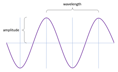 Wavelength and amplitude
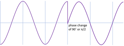 Phase modulation
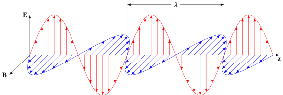 Tranverse polarization of light
Problem
Electrical transmission of data has significant distance limitations compared to optical transmission. Legacy optical encoding schemes using on/off signaling such as Non-Return to Zero (NRZ) suffer from the effects of chromatic dispersion (CD), limiting the effective distance without the use of dispersion compensation units (DCU). In order to effectively transfer data across many kilometers at rates in excess of 10 Gbps, transceivers must use coherent modulation schemes.
Solution
Changing the phase and/or amplitude of a wave encodes information as a symbol, a single unit of transmission containing one or more bits. The value of the symbol depends on the phase and amplitude measured at the receiver. All of the listed schemes can use polarization multiplexing in order to increase the data rate.
Phase Shift Keying (PSK)
PSK modulation shifts the phase of the signal in order to encode a bit or bits. As the phase of the signal can change as it traverses the fiber, the receiver measures the difference in phase between successive symbols to more accurately determine their value. This is called Differential Phase Shift Keying (DPSK).
Binary Phase Shift Keying (BPSK)
BPSK changes the phase of the signal by π radians or 180 degrees in order to encode either a 0 or a 1. The notable difference between the phases results in low Optical Signal to Noise Ratio (OSNR) requirements and signals using this modulation can travel potentially thousands of kilometers. The low number of bits per symbol limits the data rate of BPSK signals to around 100 Gbps.
 Constellation diagram of BPSK modulation
Quadrature Phase Shift Keying
QPSK changes the phase between successive symbols by π/2 radians or 90 degrees. The smaller change in phase increases information density to two bits per symbol as QPSK has four possible states.
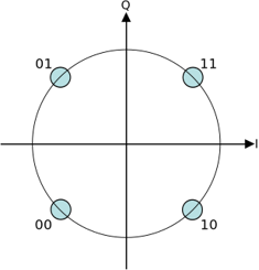 Constellation diagram of QSPK modulation
Quadrature Amplitude Modulation (QAM)
In order to further increase the number of bits per symbol, the transmitter can change the amplitude of the signal in addition to the phase. The number of points in the constellation (symbols) defines the type of QAM.
8-QAM
Eight possible states give three bits per symbol for this modulation scheme.
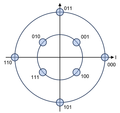 Constellation diagram of 8-QAM
16-QAM
At baud rates around 30 Gbaud, 16-QAM has a data rate of 200 Gbps. Increasing to 60 Gbaud gives rates up to 400 Gbps. Smaller changes in phase and amplitude increase the OSNR requirements and limit its range to a few hundred kilometers.
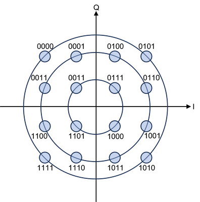 Constellation diagram of 16-QAM
32-QAM and 64-QAM
These two high-order modulation schemes use five and six bits per symbol, respectively, enabling transmission rates up to 600 Gbps. The high OSNR requirements of 64-QAM limit the effective range to less than 200 km.
 Constellation diagram of 32-QAM and 64-QAM
Polarization Multiplexing (PM)
All of the listed modulation schemes use polarization multiplexing in order to encode the transverse polarizations independently, doubling the data rate but introducing potential impairments such as Polarization Dependent Loss (PDL) and Polarization Mode Dispersion (PMD). With this technique, the data rate approximately equals the baud rate times the bits per symbol times two.
|
Modulation
|
Description
|
Bits per Symbol
|
Typical Data Rates (Gbps)
|
Example PIDs*
|
|
BPSK
|
Binary Phase Shift Keying
|
1
|
100
|
NCS1K4-1.2T-K9
|
|
QPSK
|
Quadrature Phase Shift Keying
|
2
|
100, 200
|
NCS2K-100G-CK-C
|
|
8-QAM
|
8-state Quadrature Amplitude Modulation
|
3
|
100, 200
|
NCS1K4-2-QDD-C-K9, QDD-400G-ZRP-S
|
|
16-QAM
|
16-state Quadrature Amplitude Modulation
|
4
|
200, 300, 400
|
ONS-CFP2-WDM, QDD-400G-ZRP-S, NCS2K-100G-CK-C
|
|
32-QAM
|
32-state Quadrature Amplitude Modulation
|
5
|
400, 500
|
NCS1K4-1.2T-K9
|
|
64-QAM
|
64-state Quadrature Amplitude Modulation
|
6
|
500, 600
|
NCS1K4-1.2T-K9
|
* Many PIDs support multiple modulation types. This does not represent an exhaustive list.
Optical Performance Monitoring
Cisco optical transceivers measure several different performance statistics related to coherent modulation. This section gives a brief definition of each.
- Differental Group Delay (DGD) - the difference in propagation time of the two polarization modes from transmitter to receiver measured in picoseconds.
- Chromatic Dispersion (CD) - different wavelengths travel at faster or slower rates through a waveguide (fiber). The change in propagation time per unit spectrum is measured in picosecond-nanometers (ps-nm) and accrues linearly as the signal traverses the fiber. The amount of chromatic dispersion tolerated at the receiver varies greatly depending strongly on the modulation scheme. Transceivers with a lower tolerance for dispersion require dispersion compensation units to remove this effect before reaching the receiver. Fiber types can have significantly different CD coefficients.
- Optical Signal to Noise Ratio (OSNR) - the difference between the signal energy and noise energy in dB as measured at the receiver. The OSNR value required to maintain signal integrity depends primarily on the modulation scheme used.
- Polarization Mode Dispersion (PMD) - this quantity relates to DGD and represents the total accrued difference in propagation time between the polarization modes measured in picoseconds.
- Second Order Polarization Mode Dispersion (SOPMD) - similar to chromatic dispersion, the effect of polarization mode dispersion depends on the wavelength. SOPMD characterizes this dependency with unit picoseconds squared (ps^2).
- Polarization Change Rate (PCR) - the average rate at which the polarization states change as the signal traverses the fiber measured in multiples of radians per second.
- Polarization Dependent Loss (PDL) - the effective attenuation in dB due to changes in the polarization states across the fiber.


 Feedback