Conversion of a Point-to-Point (1+1) Configuration to a Two-Fiber BLSR
Available Languages
Contents
Introduction
This document describes the procedure to upgrade a point-to-point (1+1) configuration (with two nodes) to a two-fiber bidirection line switched ring (BLSR) in an ONS 15454 network.
Prerequisites
Requirements
Cisco recommends that you have knowledge of these topics:
-
CISCO ONS 15454
Components Used
The information in this document is based on these software and hardware versions:
-
CISCO ONS 15454 version 4: All
-
CISCO ONS 15454 version 3: 3.3.0 and later
The information in this document was created from the devices in a specific lab environment. All of the devices used in this document started with a cleared (default) configuration. If your network is live, make sure that you understand the potential impact of any command.
Conventions
Refer to Cisco Technical Tips Conventions for more information on document conventions.
Background Information
This document uses a lab setup with two nodes (Node1 and Node2) (see Figure 1).
Figure 1 – Topology 
The current setup is a point-to-point (1+1) configuration. The line capacity is OC-48. The working/active and protect/standby ports reside on slot 5 and slot 6 respectively (see Figure 2).
Figure 2 – Point-to-Point (1+1) Configuration 
There are currently two circuits (see Figure 3).
Figure 3 – Two Circuits 
Convert Point-to-Point (1+1) to BLSR
Complete these steps in order to convert a point-to-point (1+1) configuration to a two-fiber BLSR ring:
-
Log into one of the two nodes.
-
Check the Alarms and Conditions tabs to ensure that there are no active alarms or conditions for the network. Resolve any network-related alarms before you proceed.
-
Click the Circuits tab (see arrow A in Figure 4).
Figure 4 – Export CTC Data: Circuits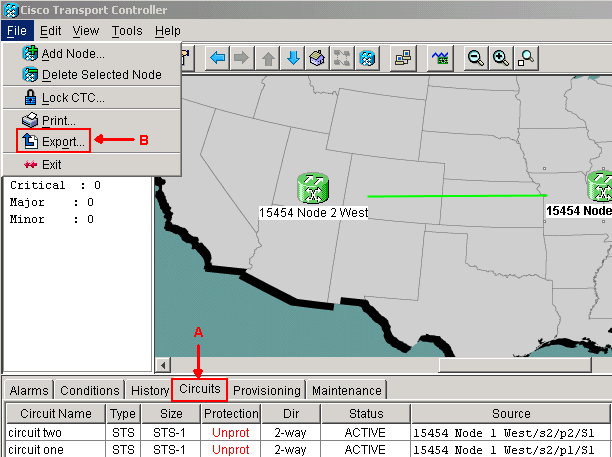
-
Export the CTC (circuits) data for reference, because you need to delete some circuits and create those circuits again later. Complete these steps:
-
Select File > Export (see arrow B in Figure 4).
-
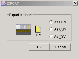
Select a data format in the EXPORT dialog box (see Figure 5). You have three options:
-
As HTML—This option saves the data as a simple HTML table file without graphics. You can view or edit the file with applications such as Netscape Navigator, Microsoft Internet Explorer, or other applications that have the capability to open HTML files.
-
As CSV—This option saves the CTC table as comma-separated values (CSV).
-
As TSV—This option saves the CTC table as tab-separated values (TSV).
-
-
Navigate to a directory where you want to store the file.
-
Click OK.
-
-
Right-click a span adjacent to the logged in node, and click Circuits from the shortcut menu (see Figure 6).
Figure 6 – Select Circuits from the Shortcut Menu
The Circuits on Span window appears (see Figure 7).
Figure 7 – Circuits on Span
-
Ensure that the total number of active Synchronous Transport Signal (STS) circuits does not exceed 50 percent of the span bandwidth. Use the circuit list that you exported in Step 4 to note any circuits that fall into the upper 50 percent of bandwidth on the span. You need to delete these circuits and create them again later in the procedure.
In the Circuit column, a block titled Unused appears (see Figure 7). This number must exceed 50 percent of the span bandwidth. For an OC-48, you must not provision more than 24 STSs on the span. For an OC-12, you must not provision more than 6 STSs on the span.
-
Repeat Steps 3 and 4 for each node involved in the point-to-point to BLSR conversion.
-
Ensure that the 1+1 working slot is active at both ends of the span that you want to convert to BLSR. Note down which slots work, and the protect port for reference in Step 12. Complete these steps:
-
Click Maintenance > Protection in the Node view.
-
Verify whether the working slot/port in the Selected Group pane appears as Working/Active under the Selected Group section (see Figure 2).
-
-
Delete a protection group at each node that supports the point-to-point span. Complete these steps:
-
Click the Provisioning > Protection tabs in the Node view.
-
Select the protection group you want to delete, and click Delete (see Figure 8).
Figure 8 – Delete a Protection Group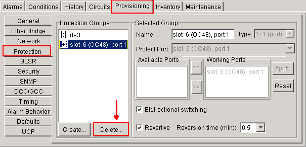
-
Click Yes in the Delete Protection Group confirmation message box.
Figure 9 – Delete Protection Group
-
Repeat Steps (a) through (d) to delete the protection group at each end of the span.
-
-
Verify the fiber from the protect port on one end node to the protect port on the other end node.
-
Create SONET Data Communication Channel (SDCC) terminations on the previous Protect slots that you noted in Step 8. On both node 1 and node 2, execute this procedure:
-
Click Circuits > DCC/GCC in the Node view (see Figure 10).
Figure 10 – Create SDCC Terminations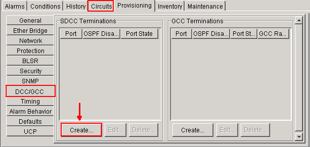
-
Click Create. The Create SDCC Terminations dialog box appears (see Figure 11).
Figure 11 – Create SDCC Terminations Dialog Box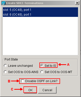
-
Click the ports for SDCC termination. In order to select more than one port, press the SHIFT key or the CTRL key.
-
Click the Set to IS radio button in the Port State area (see arrow A in Figure 11).
-
Ensure that the Disable OSPF on DCC Link check box is not checked (see arrow B in Figure 11).
-
Click OK (see arrow C in Figure 11).
-
-
For circuits you provisioned on an STS that is now part of the protection bandwidth (STSs 7 to 12 for an OC12 BLSR, STSs 25 to 48 for an OC-48 BLSR, and STSs 97 to 192 for an OC-192 BLSR), delete each circuit. Refer to the notations on the circuit list from Step 6.
Note: Deletion of circuits can affect service.
-
Select Provisioning > BLSR in the network view, and click Create BLSR (see Figure 12).
Figure 12 – BLSR Creation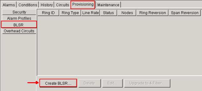
-
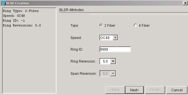
Set the BLSR properties in the BLSR Creation dialog box (see Figure 13).
-
Ring Type: Choose the BLSR ring type, either two-fiber or four-fiber.
-
Speed: Choose the BLSR ring speed
-
Ring ID: Assign a ring ID. The value must be between 0 and 9999.
-
Reversion time (Ring Reversion or Span Reversion): Set the amount of time to pass before the traffic reverts to the original working path after a ring switch. The default value is 5 minutes.
-
-
Click Next. The network graphic appears (see Figure 14).
Figure 14 – BLSR Topology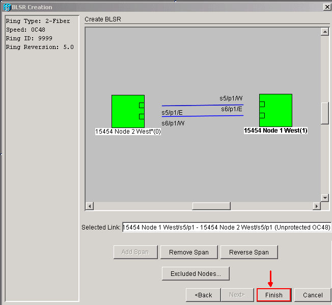
-
Double-click a BLSR span line in the network graphic. If the span line is DCC connected to other BLSR cards that constitute a complete ring, the lines turn blue and the Finish button appears. If the lines do not form a complete ring, double-click span lines until a complete ring forms.
-
Click Finish to complete the two fiber BLSR creation. The BLSR appears (see Figure 15).
Figure 15 – Verification of 2 Fiber BLSR creation
-
Recreate the circuits that you deleted in step 12.
-
In the network view, click Circuits. Under the Protection column, both circuits show 2F-BLSR (see Figure 16). Before the conversion, both circuits show 1+1 (see Figure 3).
Figure 16 – Circuits
Related Information
Revision History
| Revision | Publish Date | Comments |
|---|---|---|
1.0 |
15-Aug-2008 |
Initial Release |
Contact Cisco
- Open a Support Case

- (Requires a Cisco Service Contract)


 Feedback