ONS 15454 and ONS 15327 SONET Compatibility
Available Languages
Contents
Introduction
This document addresses the major differences and compatibility issues between the Cisco ONS 15454 and the Cisco ONS 15327 Synchronous Optical Network (SONET) Add/Drop Multiplexer (ADM) Network Elements (NE). This document encompasses software releases up to Release 4.0 on the ONS 15454 and Release 4.0 on the ONS 15327.
Product Overview and Components
The ONS 15327 is a small, cost-effective device for managed services and high-speed bandwidth aggregation for multiple services when the full capabilities of the ONS 15454 are not required. It supports DS1, DS3, Optical Carrier (OC)-3 (R3.3 and higher), OC-12, OC-48, Ethernet 10/100, and G1000(R4.0) services, and you can deploy in linear, Unidirectional Path Switched Ring (UPSR), Bi-direction line swich (BLSR R3.3) or Path Protected Mesh Network (PPMN) configurations. You may deploy the ONS 15327 along with the ONS 15454 in any of the ONS 15327's supported configurations. Figure 1 shows the ONS 15327 and the ONS 15454:
Figure 1. 15454 and 15327 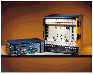
The ONS 15327 is 5.1 inches (13 cm) in height (approximately 1/3rd the height of the ONS 15454), allowing for 12 units in a 7 foot rack. Figure 2 shows the chassis layout and slot assignments for the ONS 15327.
Figure 2. 15327 Chassis and Card Assignments 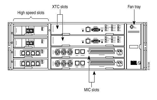
The ONS 15327 is designed for total front panel access and has four high-speed slots, each of which accommodate OC-3, OC-12, OC-48, or Ethernet 10/100/G1000 cards. There are two Common Control and Cross-Connect Cards (XTCs) that combine the functionality of the ONS 15454's Timing Communication Control (TCC) and Cross Connect with Virtual Tributary (XC-VT) cards. The Mechanical Interface Cards (MIC) act as interface cards for power, timing, alarming, and DS-n interfaces. Each of these cards is discussed in further detail below.
Chassis and Fan Tray
The ONS 15327 chassis is oriented with two columns of horizontal slots and a vertical fan tray on the right side.
Figure 3. ONS 15327 Chassis Slot Numbering 
Due to space limitations, there is no LCD display on the ONS 15327. Therefore, you must obtain the IP information and software version either through Cisco Transport Controller (CTC) or via Transaction Language 1 (TL1). For initial turn-up, on-site personnel must use the following to obtain the IP address of the network element:
-
TL1
-
Hyperterminal session
-
Straight-through DB9 cable to the craft port on the XTC card
Mechanical Interface Cards
The ONS 15327 is designed for total front panel access so there are no connectors on the backplane. This is made possible through the use of MICs in Slots 7 and 8. The MICs are (mostly) passive cards that provide interfaces for power, timing, and external alarms, as well as the physical interfaces for DS3s and DS1s. You should think of these cards as connections only, similar to the backplane connectors on the ONS 15454. The MICs do not contain any DS3 or DS1 circuitry and they do not provide protection switching operations. All DS-n functions are managed from the XTC cards, including the DS-n switching.
There are two types of MIC cards, A and B. Both cards have DS1 amphenol cable interfaces, compression-type power connectors, and RJ-45 alarm and timing interfaces. MIC A has the three DS3 transmit connections and is keyed for Slot 8. MIC B has the three receive DS3 interfaces and is keyed for Slot 7. Only one MIC is necessary to operate the 15327, but simplex operation means non-redundant power and timing and no DS3 provisioning.
Figure 4. MIC 28-3-A Card 

The ONS 15327 has redundant -48 V DC power connections on the MICs. The connectors are the compression type, similar to speaker connections on home audio systems. Redundant power is recommended and is possible with the use of two MIC cards.
The timing interface is an RJ-45 connection, rather than the wire wrap connections used on the backplane of the ONS 15454. Each MIC has one timing connection, making redundant timing possible with the use of two MIC cards. Like the ONS 15454, the ONS 15327 supports both Building Integrated Timing Supply (BITS) and line timing.
The ONS 15327 also uses an RJ-45 interface to provide user-provisionable alarms, rather than the separate Alarm Interface Controller (AIC) card on the ONS 15454. Each MIC provides three input contacts and one output contact. The use of two MICs allows for a total of six user-provisionable external input alarms and two external output controls.
The ONS 15327 uses the same DS1 amphenol cable and pinouts as the ONS 15454. You may provision fourteen DS1s on each MIC, making a total of 28 DS1s available for provisioning on each ONS 15327 with the use of two MIC cards, and an XTC-28-3. You may provision fourteen DS1s using the XTC-14 card. Protection switching and all other provisioning functions for the DS1s are performed on the XTC cards. Three DS3s are available on each ONS 15327 node.
The DS3 interfaces are divided between the two MIC cards with the transmit ports on MIC A and the receive ports on MIC B. To provision any DS3 traffic, it is also necessary to have at least one XTC-28-3 card installed. DS3s are not available with the use of XTC-14 cards. DS3 facilities are all clear channel and there is no framing or transmux functionality available on the ONS 15327.
OC-n Cards
The 15327 currently supports:
These cards have identical specifications to the conjugate cards on the ONS 15454. You can install all OCN cards in any of the four high-speed slots on the chassis, Slots 1-4.
Ethernet Cards
The 15327 supports 10/100 Ethernet on a four port card, and Ethernet traffic between the ONS 15327 and ONS 15454 is fully compatible.
Figure 6. E10/100-4 Card 
You may configure Ethernet cards as either stitched (multi-card mode) or unstitched (single-card mode). The following table summarizes the available bandwidth in each configuration. The ONS 15454 Ethernet configurations are shown for comparison.
Table 1. Ethernet Circuit Types (15454 and 15327) 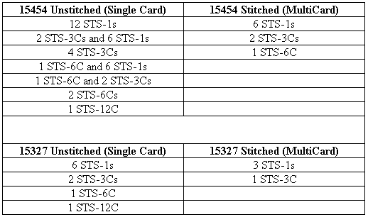
Note: STS represents the Synchronous Transport Signal
You cannot mix traffic types on the same ONS 15327 card. For example, if one STS-3C circuit is provisioned on an unstitched card, the only other traffic that can be provisioned is another STS-3C circuit; STS-1s cannot be provisioned once the STS-3C is provisioned.
G1000-2 Card
The G1000-2 provides two IEEE 802.3-compliant, 1000 Mbps ports for high-capacity customer LAN interconnections. Each port supports full-duplex operation for a maximum bandwidth of 2000 Mbps per port. The G1000-2 card uses standard small-form-factor pluggable (SFP) modules for the optical ports. SFPs are input/output devices that p lug into a Gigabit Ethernet port to link the port to the fiber-optic network. Cisco provides two SFP modules: one for short-reach applications and one for long-reach applications. The short-reach model connects to multimode fiber and the long-reach model requires single-mode fiber.
Figure 7: G1000-2 card faceplate 
XTC Cards
The XTC card is the combination controller and Cross-Connect (XC) matrix card for the ONS 15327. You can think of it as a combination of the TCC/TCC+ and XC/XC-VT cards on the ONS 15454. It performs the following functions:
-
IP address resolution
-
SONET Data Communications Channel (DCC) termination
-
Fault detection and reporting
-
Maintenance of the database for the node
The XTC card also contains the XC matrix for the node and provides the circuitry and protection switching for the DS-n interfaces located on the MIC cards.
Figure 8. XTC-28-3 Card 

The ONS 15327 supports simplex operation of the XTC cards, unlike the ONS 15454, which recommends duplex operation for both the TCC and XC-VT cards. However, for DS-n protection switching, you must deploy two XTC cards.
The ONS 15327 supports DCC terminations on each of the optical interface cards. A single node supports up to four SONET DCCs, enabling each ONS 15327 to support two UPSRs. Currently, Bidirectional Line Switch Ring (BLSR) and DCC tunneling are not supported on the ONS 15327.
There are two types of XTC cards: the XTC-14 supports 14 DS-1s but not DS-3s, and the XTC-28-3 supports 28 DS-1s and three DS-3s. You cannot mix the two types of cards within the same node, but you can within the same network. You can perform Virtual Tributary (VT) tunneling using either type of card.
XTC Matrix
The XTC-XC matrix is identical to the ONS 15454's XC-VT matrix. The XTC matrix is actually comprised of an STS and a VT matrix.
Figure 10. XTC Matrix 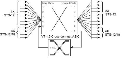
Electrical Protection
The XTC cards contain the circuitry and protection functions for the DS3 and DS1 cards. The DS3 and DS1 interfaces are on the MIC cards. The XTC card in Slot 6 is the designated working card and the XTC in Slot 5 is the designated protect card. Either card can be active and carry traffic.
To provision DS3 and DS1 cards (placing ports in service, loopbacks, and such), you must select the XTC card in Slot 6. You may not perform provisioning on the designated protect XTC in Slot 5. There is a reminder of this at the card level view of Slot 5.
Protection switching is performed with a non-revertive 1:1 protection group formed from the XTC cards. A default protection group, named XTCPROTGRP, is created when two XTC cards are present in a node. You cannot delete, rename, or edit this group. Slot 6 is the working card, by default, and Slot 5 is the protect card. DS-n circuits are automatically protected using this group.
15454 and 15327 Interoperability Issues
Software Compatibility
The ONS 15454 and the ONS 15327 are designed to be operated together in the same network. Consider the following issues regarding Java™ Runtime Environment (JRE) version and CTC files.
JRE Versions
To use CTC in ONS 15327, your computer must have a web browser with the correct Java Runtime Environment (JRE) installed for the software release in use. The correct JRE for each CTC software release is included on the Cisco ONS 15454 software CD and doc CD. If you are running multiple CTC software releases on a network, the JRE installed on the computer must be compatible with the different software releases. Table 4-1 shows JRE compatibility with ONS software releases.
Table 2: JRE Compatibility
| ONS Software Release | JRE 1.2.2 Compatible | JRE 1.3 Compatible |
|---|---|---|
| ONS 15327 Release 1.0 | Yes | No |
| ONS 15327 Release 1.0.1 | Yes | Yes |
| ONS 15327 Release 3.3 | Yes | Yes |
| ONS 15327 Release 3.4 | No | Yes |
| ONS 15327 Release 4.0 | No | Yes |
CTC Fracture
Starting with the ONS 15327 Release 1.0 and the ONS 15454 Release 3.0, the CTC has been fractured into multiple JAR files instead of the single CMS.jar file. This results in two types of CTC files: core and element Java Archive (JAR) files. Core files are common to both the ONS 15327 and the ONS 15454. Element files are unique to the particular product.
Figure 11. CTC Fracture 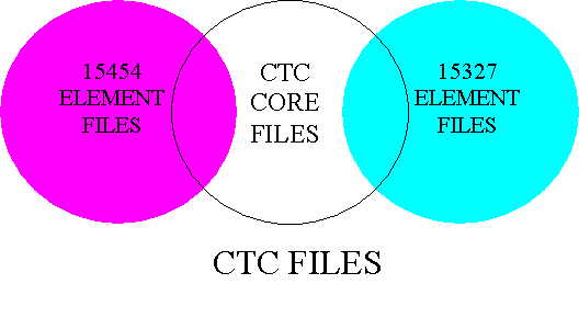
Going forward, software versions are reported separately for the Core and Element loads. Figure 21 is a screen shot of the ONS 15327 option.
Figure 12. CTC Core and Element Software Versions 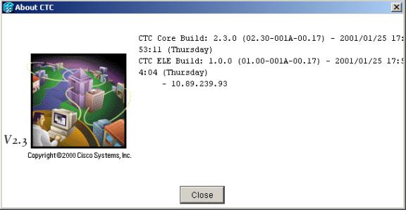
This 15327 (IP Address: 10.89.239.93) is a stand-alone node and demonstrates the fractured nature of the files. The core files that would be common to both the ONS 15327 and the ONS 15454, are part of the core build. These are from Release 2.3.0, an unreleased software load for the ONS 15454. The files that are specific to the ONS 15327 (the element files) are Release 1.0.0. If this ONS 15327 were connected to other ONS 15327s or ONS 15454s, their element versions would appear as well, with the IP addresses of the other nodes listed under the appropriate element builds.
Software Interoperability
In earlier releases, the JRE compatibility and the CTC fracture issues lead to a caveat when operating the ONS 15454 and the ONS 15327 together in the same network. To manage both nodes, launch the CTC from the node running the latest software version. Table 3 illustrates how to determine which node is running the latest software version.
Table 3. Determining From Which Node to Launch CTC 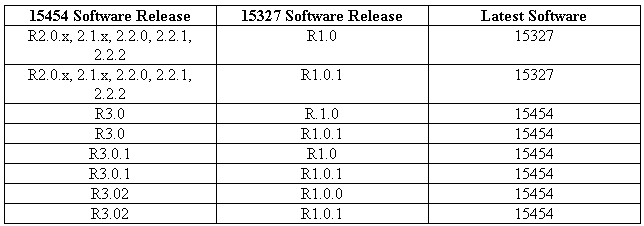
For example, if the ONS 15454 node is running Release 2.2 and the ONS 15327 is running Release 1.0, you should launch the CTC from the ONS 15327 to allow provisioning of both nodes. If the CTC is launched from the ONS 15454, then the following is true:
-
The network shows the ONS 15327 as grayed-out with an IP address.
-
There is no visibility to that node.
-
You cannot provision circuits involving that node.
-
Existing circuits involving that node appear Incomplete rather than Active.
-
No alarms or other information are available from the ONS 15327.
Note: Both the ONS 15327 and ONS 15454 are compatible starting with release 3.3, therefore you can launch CTC for either NE.
VT Mapping
The ONS 15454 uses a non-standard method of describing VT groups and numbers for VT circuit creation. The ONS 15327 organizes the VTs into seven groups of four VTs each, which is a standard grouping method. The following table shows the correlation between the ONS 15454 and ONS 15327 VTs:
Table 4. VT Mapping from 15454 to 15327 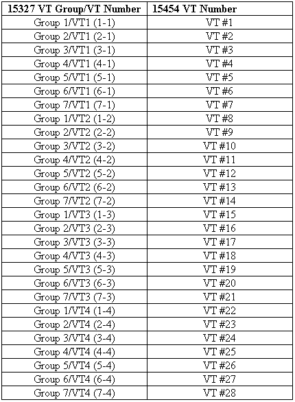
When creating VT circuits between the ONS 15327 and the ONS 15454, you should consider the different numbering schemes, particularly when trying to VT-match.
Related Information
Contact Cisco
- Open a Support Case

- (Requires a Cisco Service Contract)
 Feedback