Use NAT to Hide the Real IP Address of CTC to Establish a Session with ONS 15454
Available Languages
Contents
Introduction
This document provides a sample configuration for Network Address Translation (NAT) to establish a session between Cisco Transport Controller (CTC) and ONS 15454. The configuration hides the real IP address of CTC through NAT when CTC resides inside the firewall.
Note: For this procedure to work, you must ensure that the ports are not blocked or filtered.
Prerequisites
Requirements
Before you attempt this configuration, ensure that you have knowledge of these topics:
-
Cisco ONS 15454
-
Cisco Routers that support NAT
Components Used
The information in this document is based on these software and hardware versions:
-
Cisco ONS 15454 version 5.0 and later
-
Cisco IOS® Software Release 12.1(11) and later
The information in this document was created from the devices in a specific lab environment. All of the devices used in this document started with a cleared (default) configuration. If your network is live, make sure that you understand the potential impact of any command.
Conventions
For more information on document conventions, refer to the Cisco Technical Tips Conventions.
Background Information
Topology
The topology consists of these elements:
-
One Cisco ONS 15454
-
One PC
-
Two Cisco 2600 series routers
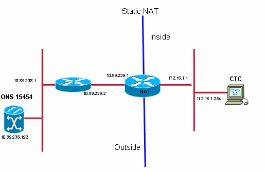
Cisco ONS 15454 resides in the external network, and acts as the server. The PC resides in the internal network, and serves as the CTC client.
Configure
In this section, you are presented with the information to configure the features described in this document.
Note: To find additional information on the commands used in this document, use the Command Lookup Tool (registered customers only) .
Network Diagram
This document uses this network setup:

Configurations
This document uses these configurations:
-
Cisco ONS 15454
-
PC
-
Cisco 2600 series routers
Cisco ONS 15454 Configuration
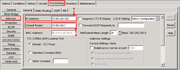
10.89.238.192 is the IP address of the ONS 15454 (see arrow A in Figure 2), and 10.89.238.1 represents the default router (see arrow B in Figure 2).
Figure 2 – ONS 15454 Configuration 
PC Configuration
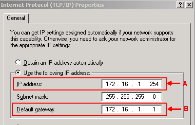
172.16.1.254 is the IP address of the PC (see arrow A in Figure 3), and 172.16.1.1 represents the default gateway (see arrow B in Figure 3). NAT translates the IP address to 10.89.239.100 for security reasons. The Cisco 2600 series router provides the necessary support for NAT and routing.
Figure 3 – PC Configuration 
Router Configuration
Complete these steps to configure NAT support on the routers:
-
Configure the outside interface.
!
interface Ethernet1/1
 ip address 10.89.239.1 255.255.255.0
 ip nat outside
!
-
Configure the inside interface where the PC resides.
interface Ethernet1/2
 ip address 172.16.1.1 255.255.255.0
 ip nat inside
!
-
Configure static NAT.
!
ip nat inside source static 172.16.1.254 10.89.239.100
!
The configuration converts the IP address 172.16.1.254 (inside local) (see arrow B in Figure 4) to 10.89.239.100 (inside global) (see arrow A in Figure 4).
-
Issue the show ip nat translations command on the router.
Figure 4 – IP NAT Translations
Verify
This section provides information you can use to confirm your configuration is working properly.
Verification Procedure
Complete these steps:
-
Run Microsoft Internet Explorer.
-
Type http://10.89.238.192 in the Address bar of the browser window, and press ENTER.
The CTC Login window appears.
-
Type your User Name and Password to log in.
CTC client must successfully establish a session with the ONS 15454.
Troubleshoot
This section provides information you can use to troubleshoot your configuration.
Troubleshooting Commands
Certain show commands are supported by the Output Interpreter Tool (registered customers only) , which allows you to view an analysis of show command output.
Note: Before issuing debug commands, refer to Important Information on Debug Commands.
-
debug ip nat detailed—turns on the IP NAT detailed trace.
The output of the debug ip nat command indicates the address translations. For example, NAT translates 172.16.1.254 to 10.89.239.100 when CTC sends data to ONS 15454 (see arrow A in Figure 5). Similarly, NAT translates 10.89.239.100 to 172.16.1.254 when CTC receives data from ONS 15454 (see arrow B in Figure 5).
Figure 5 – Debug IP NAT Detailed 
Related Information
Revision History
| Revision | Publish Date | Comments |
|---|---|---|
1.0 |
09-Jan-2006 |
Initial Release |
Contact Cisco
- Open a Support Case

- (Requires a Cisco Service Contract)

 Feedback