ONS15454 IP Addressing with Secure Mode Enabled
Available Languages
Download Options
Bias-Free Language
The documentation set for this product strives to use bias-free language. For the purposes of this documentation set, bias-free is defined as language that does not imply discrimination based on age, disability, gender, racial identity, ethnic identity, sexual orientation, socioeconomic status, and intersectionality. Exceptions may be present in the documentation due to language that is hardcoded in the user interfaces of the product software, language used based on RFP documentation, or language that is used by a referenced third-party product. Learn more about how Cisco is using Inclusive Language.
Contents
Introduction:
The document describes the basic configuration IP address assigned to the ONS 15454 node with Secure Mode Enabled in Cisco transport controller (CTC).
Prerequisites:
Cisco recommends the basic knowledge of TCP/IP and Data communication network(DCN) management in network.
Requirements:
OSN15454 Controller cards for ONS device
ONS Platform specific system software
Background Information:
If TCC2P cards are installed, dual IP addressing is available using the secure mode. When secure mode is off (sometimes called repeater mode), the IP address entered in the IP Address field applies to the ONS 15454 backplane LAN port and the TCC2P TCP/IP (LAN) port. When secure mode is on, the IP Address field shows the address assigned to the TCC2P TCP/IP (LAN) port and the Superuser can enable or disable display of the backplane IP address.
The TCC2, TCC2P, TCC3, TNC, TNCE, TSC, and TSCE cards default to repeater mode. In this mode, the front and back Ethernet (LAN) ports share a single MAC address and IP address. TCC2P, TCC3, TNC, TNCE, TSC, and TSCE cards allow you to place a node in secure mode, which prevents a front-access craft port user from accessing the LAN through the backplane port.
Secure Mode Behaviour:
Changing a TCC2P, TCC3, TNC, TNCE, TSC, or TSCE node from repeater mode to secure mode allows you to provision two IP addresses for the ONS 15454 and causes the node to assign the ports different MAC addresses. In secure mode, one IP address is provisioned for the ONS 15454 backplane LAN port, and the other IP address is provisioned for the card Ethernet port. Both addresses reside on different subnets, providing an additional layer of separation between the craft access port and the ONS 15454 LAN. If secure mode is enabled, the IP addresses provisioned for the backplane LAN port and card Ethernet port must follow general IP addressing guidelines and must reside on different subnets from each other.
In secure mode, the IP address assigned to the backplane LAN port becomes a private address, which connects the node to an operations support system (OSS) through a central office LAN or private enterprise network. A Superuser can configure the node to hide or reveal the backplane's LAN IP address in CTC, the routing table, or TL1 autonomous message reports.
In repeater mode, a node can be a GNE or ENE. Placing the node into secure mode automatically turns on SOCKS proxy and defaults the node to GNE status. However, the node can be changed back to an ENE. In repeater mode, an ENE’s SOCKS proxy can be disabled—effectively isolating the node beyond the LAN firewall—but it cannot be disabled in secure mode. The Net/Subnet Mask Length—Type the subnet mask length (decimal number representing the subnet mask length in bits) or click the arrows to adjust the subnet mask length. The subnet mask length is the same for all ONS 15454 nodes in the same subnet. The MAC Address—(Display only) displays the ONS 15454 IEEE 802 MAC address.
In secure mode, the front and back TCP/IP (LAN) ports are assigned different MAC addresses, and the backplane information can be hidden or revealed by a Superuser.
The IP address assigned to the TCC2P TCP/IP (LAN) port must reside on a different subnet from the backplane LAN port and the ONS 15454 default router. Verify that the new TCC2P IP address meets this requirement and is compatible with ONS 15454 network IP addresses.
Procedure to change to secure mode via CTC:
Step 1 Click the Provisioning > Security > Data Comm tabs as shown below:

Step 2 Click Change Mode.
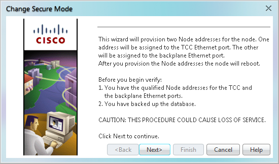
Step 3 Review the information on the Change Secure Mode page, then click Next.
Step 4 On the TCC Ethernet Port page, enter the IP address and subnet mask for the TCC2P TCP/IP (LAN) port. The IP address cannot reside on the same subnet as the backplane LAN port or the ONS 15454 default router and if that is not the case the below error will occur in CTC.
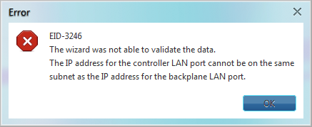
Step 5 Click Next after assuring step-4.
Step 6 If needed, on the Backplane Ethernet Port page, modify the backplane IP address, subnet mask, and default router. (You normally do not modify these fields if no ONS 15454 network changes have occurred.)
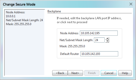
Step 7 Click Next.
Step 8 On the SOCKS Proxy Server Settings page, choose one of the following options:
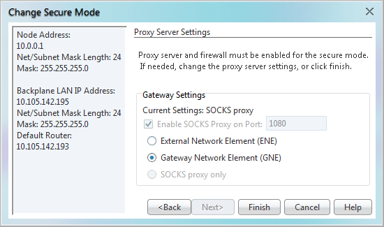
- External Network Element (ENE)—If selected, the CTC computer is only visible to the ONS 15454 where the CTC computer is connected. The CTC computer is not visible to the nodes connected to the DCC. In addition, firewall is enabled, which means that the node prevents IP traffic from being routed between the DCC and the LAN port.
- Gateway Network Element (GNE)—If selected, the CTC computer is visible to other DCC-connected nodes. The node prevents IP traffic from being routed between the DCC and the LAN port.
Note: The SOCKS proxy server is automatically enabled when you enable secure mode.
Step 9 Click Finish.
Within the next 30 to 40 seconds, the TCC2P cards reboot. CTC switches to network view, and the CTC Alerts dialog box appears. In network view, the node changes to grey and a DISCONNECTED condition appears in the Alarms tab.
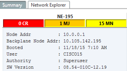
After enabling the secure mode in CTC verify if they have correctly defined for node as shown below for one test node.

Also verify both IP address in CTC node view as shown below.
Secure Node Locked and Unlocked Behaviour:
Secure mode can be locked or unlocked on a node operating in secure mode. The default status is unlocked, and only a Superuser can issue a lock. When secure mode is locked, the node’s configuration (including Ethernet port status) and lock status cannot be changed by any network user. To have a secure node’s lock removed, contact Cisco Technical Support to arrange a Return Material Authorization (RMA) for the shelf assembly. Enabling a lock makes a permanent change to the shelf’s EEPROM.
A node’s configuration lock is maintained if the active TCC2P card’s database is reloaded. For example, if you attempt to load an unlocked node database onto a locked node’s standby TCC2P card for transfer to the active TCC2P card (an action that is not recommended), the unlocked node’s status (via the uploaded database) will not override the node’s lock status. If you attempt to load a locked database onto the standby TCC2P card of an unlocked secure node, the active TCC2P card will upload the database. If the uploaded defaults indicate a locked status, this will cause the node to become locked. If a software load has been customized before a lock is enabled, all lockable provisioning features are permanently set to the customized NE defaults provided in the load and cannot be changed by any user.
Useful notes:
- If both front and backplane access ports are disabled in an ENE and the node is isolated from DCC communication (due to user provisioning or network faults), the front and backplane ports are automatically re-enabled.
- Secure mode can be locked, which prevents the mode from being altered.
- Enabling secure mode causes the TCC2P, TCC3, TNC, TNCE, TSC, and TSCE cards to reboot; the card reboot affects traffic.
- The security mode options are not available in CTC if TCC2 cards or a mix of TCC2 and TCC2P cards are installed.
- Enabling secure mode causes the TCC2P card to reboot; a TCC2P card reboot affects traffic.
- The TCC2 card fails to boot when it is added as a standby card to a node containing an active TCC2P card configured in the secure mode.
Contributed by Cisco Engineers
Contact Cisco
- Open a Support Case

- (Requires a Cisco Service Contract)
 Feedback