Troubleshoot MST on Catalyst 9000 Switches
Available Languages
Download Options
Bias-Free Language
The documentation set for this product strives to use bias-free language. For the purposes of this documentation set, bias-free is defined as language that does not imply discrimination based on age, disability, gender, racial identity, ethnic identity, sexual orientation, socioeconomic status, and intersectionality. Exceptions may be present in the documentation due to language that is hardcoded in the user interfaces of the product software, language used based on RFP documentation, or language that is used by a referenced third-party product. Learn more about how Cisco is using Inclusive Language.
Contents
Introduction
This document describes basic concepts needed to understand how MST works in a topology with either PVST or other regions.
Prerequisites
Requirements
Cisco recommends that you have knowledge of these topics:
- Rapid-PVST (Rapid Per VLAN Spanning Tree)
Components Used
The information in this document is based on these software and hardware versions:
-
Catalyst 9300.
- From 17.3 train onward.
The information in this document was created from the devices in a specific lab environment. All of the devices used in this document started with a cleared (default) configuration. If your network is live, ensure that you understand the potential impact of any command.
Related Products
This document can also be used with these hardware:
-
All Catalyst 9000 Family.
Background Information
Terminology
Before start and apply any kind of troubleshoot, please consider this terminology:
|
Concept |
Description |
|
STP Instance |
An instance is one session that runs in your CPU: On PVST, one VLAN is an instance in. On MST an instance is a group of VLANs. This document would use the term instance based on this meaning. |
|
IST |
IST (Internal Spanning Tree) is also known as Instance 0 or MSTI0: - This is a special instance. The IST is the only spanning tree instance that sends and receives BPDUs. All of the other spanning tree instance information is contained in M-records, which are encapsulated within MSTP BPDUs. Because the MSTP BPDU carries information for all instances. This is the only instance that has timer related parameters.When MST communicates to other regions and versions of spanning tree, the IST or MSTI0’s settings are what are used to communicate. |
|
MSTIs |
MSTIs stands for Multiple Spanning Tree Instances. From 1 to 15 The Cisco implementation supports 16 instances: one IST (instance 0) and 15 MSTIs. |
|
Region |
A group of switches that run MST. All of them have the same MST configuration. |
|
CIST and CST |
- The Common Spanning Tree interconnects the MST regions and single spanning trees. - A Common and Internal Spanning Tree is a collection of the ISTs in each MST region and Common Spanning Tree. |
|
Regional Root |
This is the election process for each instance in a region with the exception of instance 0. It is possible to have a different root in a spanning tree region for each instance if needed. This is done if it is considered the information in the IST BPDU that has the information required to perform a normal spanning tree election. The CIST root bridge was called the IST master in the prestandard implementation. If the CIST root bridge is in the region, the regional root is the CIST root bridge. Otherwise, the regional root is the closest switch to the CIST root in the region. The regional root acts as a root bridge for the IST. |
|
M-Record |
Since there is only one BPDU, and that BPDU reflects the information required to converge instance 0, it is needed another mechanism to form roots for other instances. This is called an M-Record. Inside each M-Record is all of the spanning tree information for an individual instance. |
|
Dispute |
The Dispute mechanism is a built in unidirectional link detection mechanism. This is not available in the original version of 802.1d (RSTP was actually integrated into the 802.1d standard in 2004) or PVST. The dispute mechanism is triggered on receipt of an inferior BPDU that has a designated state and is in a learning and forwarding state.. |
|
Proposal / Agreement |
This Proposal agreement mechanism is one of the most important changes to RSTP. This is what allows rapid spanning tree to actually be rapid. When the inferior switch recognizes this port is not a root bridge and has the best path to the root, it no longer has the proposal bit set, and transitions to Root state and forwarding. |
|
Shared Segments |
RSTP / MST put a half duplex link in a “shared” state. This means that the Proposal Agreement process does not happen. Since the sequence is meant to rapidly bring up P2P links, a premature transition to a forward state could case a loop. This can be seen in the show commands for spanning tree You can enter spanning-tree link-type point-to-point on the interface to force it to be in P2P state, please used it carefully. |
|
Multiple Regions |
•Multiple regions are determined when MST configurations do not match. •The CIST is elected between Regions via the MSTI0 BPDU •Multiple regions appear as one logical switch per region to other devices. |
|
Boundary Port |
These ports are on the limits of the Region, commonly on these ports non-MST BPDUs are received, so MST is not possible on this port. PVST Simulation is the way MST and PVST can work on the same network. |
|
PVST Simulation |
In certain scenarios, like migrations or changes in the topology of a network, more than one STP Flavor are found together and an MST region is connected to another domain. As an example, a network that changes from PVST+ to MST and all the switches cannot be modified at the same time. Also, there is a need to work with MST and PVST+ together. Since PVST+ cannot process MST BPUSs, there is a compatibility mechanism between them, so both protocols can interact. This compatibility mechanism is called PVST simulation. |
|
PVST Simulation Failure |
If the rules stated on PVST simulation are not met |
Restrictions
-
PVST+, Rapid PVST+, and MSTP are supported, but only one version can be active at any time. (For example, all VLANs run PVST+, all VLANs run Rapid PVST+, or all VLANs run MSTP.)
-
VLAN Trunking Protocol (VTP) propagation of the MST configuration is not supported.
Troubleshoot
The goal is to have the MST region to behave like a virtual CST bridge, from the perspective outside the region.
Other switches, either in a different the region or in a PVST domain, see the MST region as only one switch because RootID and Root Path cost are left unchanged.
MST (single region)
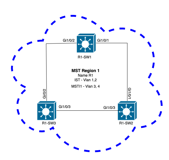
Topology
Configuration
These three attributes must be configured in the same way on all switches under an MST region to converge properly. Commands are applied under MST configuration mode.
- Name
- Revision number
- VLAN to instance mapping
spanning-tree mst configuration
name <region name>
revision <number>
instance <number> vlan <vlan number>
Validate attributes configuration with this command:
show running-config | section span
Example: attributes configuration for switches 1, 2, and 3 in region 1
R1-SW1
R1-SW1#show running-config | section spann
spanning-tree mode mst
spanning-tree extend system-id
spanning-tree mst configuration
 name R1               <---
 revision 1            <---
 instance 1 vlan 3-4   <---
R1-SW2
R1-SW2#show running-config | section spann
spanning-tree mode mst
spanning-tree extend system-id
spanning-tree mst configuration
 name R1
 revision 1
 instance 1 vlan 3-4
R1-SW3
R1-SW3#show running-config | section spann
spanning-tree mode mst
spanning-tree extend system-id
spanning-tree mst configuration
 name R1
 revision 1
 instance 1 vlan 3-4
Validation
During MST migration, you can configure MST parameters without the need to change the STP mode yet.
Follow these recomendations to avoid possible network disruptions due to misconfiguration.
- Check MST configuration before commit.
- Check MST configuration after commit
Check MST configuration before commit.
This check is when spanning-tree mode mst has not been applied yet.
show spanning-tree mst
show current
show spanning-tree mst configuration digest
Note: show current is only available under MST configuration mode (spanning-tree mst configuration submode)
Example: For switch 1 in region 1
Verify STP mode is not in MST mode yet
R1-SW1#show spanning-tree mst
% Switch is not in mst mode   <--
Verify current MST configuration
R1-SW1(config-mst)#show current
Current MST configuration
Name      [R1]
Revision  1     Instances configured 2

Instance  Vlans mapped
--------  ---------------------------------------------------------------------
0         1-2,6-4094
1         3-4
-------------------------------------------------------------------------------
Note: show current is only available under MST configuration mode.
Note: show span mst configuration and show current are equivalent commands.
Verify digest hash
R1-SW1#show spanning-tree mst configuration digest
% Switch is not in mst mode                          <--
Name [R1]
Revision 1 Instances configured 2
Digest 0xA423B8DBB209CCF6560F55618AB58726            <--
Pre-std Digest 0x8C9BE88BBC9B84CB8AED635EE008436A
Note: Digest output lets you know whether or not the switch is already in MST mode. Digest hash does not change, even if the MST mode has not been enabled yet.
Note: Catalyst 9000 switches run the IEEE standard MST protocol. Therefore you must focus on the Digest hash instead of the Pre-std Digest
Check MST configuration after commit
show current
show pending
show spanning-tree mst configuration digest
abort
Note: show pending (as well as show current) is only available under the MST configuration mode
The show current output shows you the MST configuration after exit the MST submode (which is when config change is applied) whereas the show pending output show you the MST configuration that has been recently configured, but not applied.
If for any reason you need to revert the config changes and you are still under the MST submode, then you can apply the abort command which exit from the MST submode without apply the changes.
Note: show pending (as well as show current) is only available under the MST configuration mode
Example: For switch 1 in region 1
Notice that current and pending configurations are the same, this mean no changes have been made.
Digest hash is the same as one validated in the previous output.
R1-SW1(config)#spanning-tree mst configuration
R1-SW1(config-mst)#show current
Current MST configuration
Name      [R1]
Revision  1     Instances configured 2

Instance  Vlans mapped
--------  ---------------------------------------------------------------------
0         1-2,5-4094
1         3-4
-------------------------------------------------------------------------------

R1-SW1(config-mst)#show pending
Pending MST configuration
Name      [R1]
Revision  1     Instances configured 2

Instance  Vlans mapped
--------  ---------------------------------------------------------------------
0         1-2,5-4094
1         3-4
-------------------------------------------------------------------------------

R1-SW1(config-mst)#do show spanning-tree mst configuration digest
Name      [R1]
Revision  1     Instances configured 2
Digest          0xA423B8DBB209CCF6560F55618AB58726   <--
Pre-std Digest  0x8C9BE88BBC9B84CB8AED635EE008436A
New instance is created and VLAN 5 is mapped to it. This time the show current output does not show the new instance recently condigured, but show pending does. This is expected.
Notice that Digest hash has not changed. This is because new config only applies when you exit from the MST configuration mode (spanning-tree mst configuration submode)
 R1-SW1(config-mst)#instance 2 vlan 5       <--
R1-SW1(config-mst)#show current
Current MST configuration
Name      [R1]
Revision  1     Instances configured 2

Instance  Vlans mapped
--------  ---------------------------------------------------------------------
0         1-2,5-4094
1         3-4
-------------------------------------------------------------------------------

R1-SW1(config-mst)#show pending
Pending MST configuration
Name      [R1]
Revision  1     Instances configured 3

Instance  Vlans mapped
--------  ---------------------------------------------------------------------
0         1-2,6-4094
1         3-4
2         5     <--
-------------------------------------------------------------------------------

R1-SW1(config-mst)#do show spanning-tree mst configuration digest
Name      [R1]
Revision  1     Instances configured 2
Digest          0xA423B8DBB209CCF6560F55618AB58726     <--
Pre-std Digest  0x8C9BE88BBC9B84CB8AED635EE008436A
After exit from the MST configuration mode, changes are reflected. Digest hash is also re-calculated to match with the new changes made.
R1-SW1(config-mst)#exit
R1-SW1(config)#spanning-tree mst configuration
R1-SW1(config-mst)#show current
Current MST configuration
Name      [R1]
Revision  1     Instances configured 3

Instance  Vlans mapped
--------  ---------------------------------------------------------------------
0         1-2,6-4094
1         3-4
2         5       <--
-------------------------------------------------------------------------------

R1-SW1(config-mst)#show pending
Pending MST configuration
Name      [R1]
Revision  1     Instances configured 3

Instance  Vlans mapped
--------  ---------------------------------------------------------------------
0         1-2,6-4094
1         3-4
2         5     <--
-------------------------------------------------------------------------------


R1-SW1(config-mst)#do show spanning-tree mst configuration digest
Name      [R1]
Revision  1     Instances configured 3
Digest          0x083305551908B9A2CC50B482DC577B8F     <--
Pre-std Digest  0xA8AC09BDF2942058FAF4CE727C9D258F
These commands are helpful to validate MST parameters and convergency. Also they provide information related to MST timers, cost, and so on.
show spanning-tree pathcost method
show spanning-tree root
show spanning-tree summary
show spanning-tree mst
show spanning-tree interface <interface>
Note: show spanning-tree mst and show spanning-tree are equivalent
Example: For switch 1 in region 1
There are two methods to measure the path cost, short (legacy) and long. It is always preferable to be homogeneous along your layer 2 network. If you run long pathcost method, do it along all your switches wich run on STP.
R1-SW1#show spanning-tree pathcost method
Spanning tree default pathcost method used is long  <--
This output lets you now the path cost method, but also lets you know the switch run standard MST protocol and uses the extended system ID (which is a must when MST is used).
R1-SW1#show spanning-tree summary
Switch is in mst mode (IEEE Standard)               <--
Root bridge for: none
EtherChannel misconfig guard            is enabled
Extended system ID                      is enabled  <--
Portfast Default                        is disabled
PortFast BPDU Guard Default            is disabled
Portfast BPDU Filter Default           is disabled
Loopguard Default                      is disabled
UplinkFast                              is disabled
BackboneFast                            is disabled
Configured Pathcost method used is long             <--

Name                   Blocking Listening Learning Forwarding STP Active
---------------------- -------- --------- -------- ---------- ----------
MST0                         0         0        0          3          3
MST1                         0         0        0          3          3
---------------------- -------- --------- -------- ---------- ----------
2 msts                       0         0        0          6          6
Bridge and root IDs, priorities, costs, port roles and status as well as VLAN mapping can be observed in this output:
R1-SW1#show spanning-tree mst

##### MST0    vlans mapped:   1-2,5-4094
Bridge        address 3473.2db8.be80  priority      32768 (32768 sysid 0)
Root          address f04a.021e.9500  priority      24576 (24576 sysid 0)
              port    Gi1/0/2         path cost     0
Regional Root address f04a.021e.9500  priority      24576 (24576 sysid 0)
                                      internal cost 20000     rem hops 19
Operational   hello time 2 , forward delay 15, max age 20, txholdcount 6
Configured    hello time 2 , forward delay 15, max age 20, max hops    20

Interface                        Role Sts Cost      Prio.Nbr Type
----------------                 ---- --- --------- -------- --------------------------------
Gi1/0/1                          Desg FWD 20000     128.1    P2p
Gi1/0/2                          Root FWD 20000     128.2    P2p
Gi1/0/4                          Desg FWD 20000     128.4    P2p

##### MST1    vlans mapped:   3-4
Bridge        address 3473.2db8.be80  priority      32769 (32768 sysid 1)
Root          address f04a.021e.9500  priority      24577 (24576 sysid 1)
              port    Gi1/0/2         cost          20000     rem hops 19

Interface                        Role Sts Cost      Prio.Nbr Type
----------------                 ---- --- --------- -------- --------------------------------
Gi1/0/1                          Desg FWD 20000     128.1    P2p
Gi1/0/2                          Root FWD 20000     128.2    P2p
Gi1/0/4                          Desg FWD 20000     128.4    P2p
This command shows you the STP roles status, priority, and link type from interface perspective instead of per instance perspective.
R1-SW1#show spanning-tree interface gigabitEthernet 1/0/1

Mst Instance        Role Sts Cost      Prio.Nbr Type
------------------- ---- --- --------- -------- --------------------------------
MST0                Desg FWD 20000     128.1    P2p
MST1                Desg FWD 20000     128.1    P2p

R1-SW1#show spanning-tree interface gigabitEthernet 1/0/2

Mst Instance        Role Sts Cost      Prio.Nbr Type
------------------- ---- --- --------- -------- --------------------------------
MST0                Root FWD 20000     128.2    P2p
MST1                Root FWD 20000     128.2    P2p
Synchronization between regions
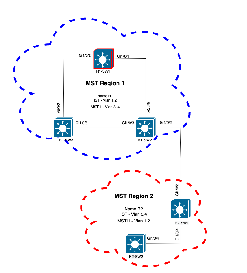
Region 2 has been added to the topology. The purpose is to check the process of how two different regions interact and converge. Only the boundary switches take place in this communication.
Since both ends of the link have the same process of communication. This section focuses on the outputs of show spanning-tree mst of R1-SW2 and two BPDUs taken from a packet capture.
Topology
Validation
This is the initial communication between R1-SW2 from Region 1 and R2-SW1 from Region 2. As soon as a connection is established between both devices, they send a BPDU.
Focus on interface Gi1/0/2 from R2-SW1, which is blocking (BLK) as initial state. Remember that a switch port enters the BLK state at time of election process.
R2-SW1#show spanning-tree mst

MST0
! Output omitted for brevity

Interface           Role Sts Cost      Prio.Nbr Type
------------------- ---- --- --------- -------- --------------------------------
Gi1/0/2             Desg BLK 20000     128.2    P2p
Gi1/0/4             Root FWD 20000     128.4    P2p

MST1
! Output omitted for brevity

Interface           Role Sts Cost      Prio.Nbr Type
------------------- ---- --- --------- -------- --------------------------------
Gi1/0/2             Desg BLK 20000     128.2    P2p
Gi1/0/4             Root FWD 20000     128.4    P2p
In the packet capture it is observed this first BPDU, with the Port Role flags shown as Designated and the Proposal.
This means that the communication already started and both ports started the process of syncronization to establsh an agreement and set the port roles and states. All start with the proposal mechanism.
IEEE 802.3 Ethernet
    Destination: Spanning-tree-(for-bridges)_00 (01:80:c2:00:00:00)
    Source: Cisco_05:d6:02 (f0:4a:02:05:d6:02)
    Length: 121
Logical-Link Control
Spanning Tree Protocol
    Protocol Identifier: Spanning Tree Protocol (0x0000)
    Protocol Version Identifier: Multiple Spanning Tree (3)
    BPDU Type: Rapid/Multiple Spanning Tree (0x02)
    BPDU flags: 0x0e, Port Role: Designated, Proposal
        0... .... = Topology Change Acknowledgment: No
        .0.. .... = Agreement: No
        ..0. .... = Forwarding: No
        ...0 .... = Learning: No
        .... 11.. = Port Role: Designated (3)
        .... ..1. = Proposal: Yes
        .... ...0 = Topology Change: No
    Root Identifier: 24576 / 0 / f0:4a:02:1e:95:00
    Root Path Cost: 20004
    Bridge Identifier: 32768 / 0 / a0:f8:49:10:47:80
    Port identifier: 0x8002
    Message Age: 2
    Max Age: 20
    Hello Time: 2
    Forward Delay: 15
    Version 1 Length: 0
    Version 3 Length: 80
    MST Extension
After BPDUs exchange between switches, the state changes to learning (LRN).
After R2-SW1 receives the first BPDU previously shown, LRN state is the first transitional state after blocking state.
R2-SW1#show spanning-tree mst

MST0
! Output omitted for brevity

Interface           Role Sts Cost      Prio.Nbr Type
------------------- ---- --- --------- -------- --------------------------------
Gi1/0/2             Desg LRN 20000     128.2    P2p
Gi1/0/4             Root FWD 20000     128.4    P2p

MST1
! Output omitted for brevity

Interface           Role Sts Cost      Prio.Nbr Type
------------------- ---- --- --------- -------- --------------------------------
Gi1/0/2             Desg LRN 20000     128.2    P2p
Gi1/0/4             Root FWD 20000     128.4    P2p
Once one of the peer establish an agreement and the synchronization takes place (the neighbor is accepted as the superior path to the root), the links immediately transition to forwarding state.
Here you can observe the BPDU with the Flags set as learning, it also includes the topology change notification flag which is triggered as soon as the port transitions from LRN to forwarding (FWR).
In this state, MST determines whether the port participates in frame forwarding or not (state BLK).
IEEE 802.3 Ethernet
Logical-Link Control
Spanning Tree Protocol
    Protocol Identifier: Spanning Tree Protocol (0x0000)
    Protocol Version Identifier: Multiple Spanning Tree (3)
    BPDU Type: Rapid/Multiple Spanning Tree (0x02)
    BPDU flags: 0x3d, Forwarding, Learning, Port Role: Designated, Topology Change
        0... .... = Topology Change Acknowledgment: No
        .0.. .... = Agreement: No
        ..1. .... = Forwarding: Yes
        ...1 .... = Learning: Yes
        .... 11.. = Port Role: Designated (3)
        .... ..0. = Proposal: No
        .... ...1 = Topology Change: Yes
    Root Identifier: 24576 / 0 / f0:4a:02:1e:95:00
    Root Path Cost: 20004
    Bridge Identifier: 32768 / 0 / a0:f8:49:10:47:80
    Port identifier: 0x8002
    Message Age: 2
    Max Age: 20
    Hello Time: 2
    Forward Delay: 15
    Version 1 Length: 0
    Version 3 Length: 80
    MST Extension
Finally, Switch port enters to forwarding state after traverse all the states involved in creation of network topology.
This would be the last state of the port, with the role designated (Desg) and status FDW.
R2-SW1#show spanning-tree mst

MST0
! Output omitted for brevity

Interface           Role Sts Cost      Prio.Nbr Type
------------------- ---- --- --------- -------- --------------------------------
Gi1/0/2             Desg FWD 20000     128.2    P2p
Gi1/0/4             Root FWD 20000     128.4    P2p


MST1
! Output omitted for brevity

Interface           Role Sts Cost      Prio.Nbr Type
------------------- ---- --- --------- -------- --------------------------------
Gi1/0/2             Desg FWD 20000     128.2    P2p
Gi1/0/4             Root FWD 20000     128.4    P2p
Debugs
These bugs were enabled during communication between R2-SW1 and R1-SW2.
debug spanning-tree mstp roles
debug spanning-tree mstp tc
debug spanning-tree mstp boundary
Example:
R2-SW1#show debugging
Packet Infra debugs:

Ip Address                                               Port
------------------------------------------------------|----------

Multiple Spanning Tree:
  MSTP port ROLES changes debugging is on
  MSTP Topology Change notifications debugging is on
  MSTP port BOUNDARY flag changes debugging is on
Logs observed
%LINK-3-UPDOWN: Interface GigabitEthernet1/0/2, changed state to down
%LINK-3-UPDOWN: Interface GigabitEthernet1/0/2, changed state to up
MST[0]: Gi1/0/2 is now designated port
MST[0]: Gi1/0/2 becomes designated - clearing BOUNDARY flag
MST[1]: Gi1/0/2 is now designated port
MST[0]: port Gi1/0/2 received external tc
MST[0]: port Gi1/0/2 received external tc
MST[1]: port Gi1/0/2 received tc
MST[0]: port Gi1/0/2 received external tc
MST[0]: port Gi1/0/2 received external tc
MST[1]: port Gi1/0/2 received tc
MST[0]: port Gi1/0/2 received external tc
MST[0]: port Gi1/0/2 received external tc
MST[1]: port Gi1/0/2 received tc
MST[0]: port Gi1/0/2 initiating tc
MST[1]: port Gi1/0/2 initiating tc
MST[0]: port Gi1/0/2 received external tc
MST[0]: port Gi1/0/2 received external tc
MST[1]: port Gi1/0/2 received tcsho span
%LINEPROTO-5-UPDOWN: Line protocol on Interface GigabitEthernet1/0/2, changed state to up
MST[0]: port Gi1/0/3 received internal tc
MST[0]: port Gi1/0/3 received internal tc
MST[0]: port Gi1/0/3 received internal tc
PVST Simulation Failure
PVST simulation s the mechanism that MST uses to communicate to non MST switches.
PVST switches does not recognize MST BPDUs because they are simply different. This is why It is important to understand the differences between PVST and MST BPDUs.
PVST BPDUs vs MST BPDUs
Two BPDUs were captured, one for PVST and one for MST, look at the differences between them.
PVST
- PVST sends a BPDU for every VLAN configured on the switch. Therefore have 100 VLANS configured means 100 BPDUs are sent over all the ports to build its own loop free topology.
- PVST is based on the classic STP
Ethernet II, Src: Cisco_06:19:01 (f0:4a:02:06:19:01), Dst: PVST+ (01:00:0c:cc:cc:cd)
    Destination: PVST+ (01:00:0c:cc:cc:cd)
    Source: Cisco_06:19:01 (f0:4a:02:06:19:01)
    Type: 802.1Q Virtual LAN (0x8100)
802.1Q Virtual LAN, PRI: 7, DEI: 0, ID: 3
    111. .... .... .... = Priority: Network Control (7)
    ...0 .... .... .... = DEI: Ineligible
    .... 0000 0000 0011 = ID: 3
    Length: 50
Logical-Link Control
    DSAP: SNAP (0xaa)
    SSAP: SNAP (0xaa)
    Control field: U, func=UI (0x03)
    Organization Code: 00:00:0c (Cisco Systems, Inc)
    PID: PVSTP+ (0x010b)
Spanning Tree Protocol
    Protocol Identifier: Spanning Tree Protocol (0x0000)
    Protocol Version Identifier: Spanning Tree (0)
    BPDU Type: Configuration (0x00)
    BPDU flags: 0x01, Topology Change
        0... .... = Topology Change Acknowledgment: No
        .... ...1 = Topology Change: Yes
    Root Identifier: 32768 / 0 / 68:9e:0b:a0:f5:80
        Root Bridge Priority: 32768
        Root Bridge System ID Extension: 0
        Root Bridge System ID: Cisco_a0:f5:80 (68:9e:0b:a0:f5:80)
    Root Path Cost: 20000
    Bridge Identifier: 32768 / 0 / f0:4a:02:06:19:00
        Bridge Priority: 32768
        Bridge System ID Extension: 0
        Bridge System ID: Cisco_06:19:00 (f0:4a:02:06:19:00)
    Port identifier: 0x8001
    Message Age: 1
    Max Age: 20
    Hello Time: 2
    Forward Delay: 15
    Originating VLAN (PVID): 3
        Type: Originating VLAN (0x0000)
        Length: 2
        Originating VLAN: 3
MST
- MST sends a single BPDU for all the MST instances configured on the switch. This is achieved thanks to the MST extension (M records) which haves the information of all instances.
- MST is based on RSTP, which means that all the intrinsic mechanisms of this protocol were inherited to MST.
- Timers are defined by the IST and affects all other instances within a region
IEEE 802.3 Ethernet
    Destination: Spanning-tree-(for-bridges)_00 (01:80:c2:00:00:00)
    Source: Cisco_b8:be:81 (34:73:2d:b8:be:81)
    Length: 121
Logical-Link Control
    DSAP: Spanning Tree BPDU (0x42)
    SSAP: Spanning Tree BPDU (0x42)
    Control field: U, func=UI (0x03)
Spanning Tree Protocol
    Protocol Identifier: Spanning Tree Protocol (0x0000)
    Protocol Version Identifier: Multiple Spanning Tree (3)
    BPDU Type: Rapid/Multiple Spanning Tree (0x02)
    BPDU flags: 0x0e, Port Role: Designated, Proposal
        0... .... = Topology Change Acknowledgment: No
        .0.. .... = Agreement: No
        ..0. .... = Forwarding: No
        ...0 .... = Learning: No
        .... 11.. = Port Role: Designated (3)
        .... ..1. = Proposal: Yes
        .... ...0 = Topology Change: No
    Root Identifier: 32768 / 0 / 34:73:2d:b8:be:80
        Root Bridge Priority: 32768
        Root Bridge System ID Extension: 0
        Root Bridge System ID: Cisco_b8:be:80 (34:73:2d:b8:be:80)
    Root Path Cost: 0
    Bridge Identifier: 32768 / 0 / 34:73:2d:b8:be:80
        Bridge Priority: 32768
        Bridge System ID Extension: 0
        Bridge System ID: Cisco_b8:be:80 (34:73:2d:b8:be:80)
    Port identifier: 0x8001
    Message Age: 0
    Max Age: 20
    Hello Time: 2
    Forward Delay: 15
    Version 1 Length: 0
    Version 3 Length: 80
    MST Extension
        MST Config ID format selector: 0
        MST Config name: R1
        MST Config revision: 1
        MST Config digest: a423b8dbb209ccf6560f55618ab58726
        CIST Internal Root Path Cost: 0
        CIST Bridge Identifier: 32768 / 0 / 34:73:2d:b8:be:80
            CIST Bridge Priority: 32768
            CIST Bridge Identifier System ID Extension: 0
            CIST Bridge Identifier System ID: Cisco_b8:be:80 (34:73:2d:b8:be:80)
        CIST Remaining hops: 20
        MSTID 1, Regional Root Identifier 32768 / 34:73:2d:b8:be:80
            MSTI flags: 0x0e, Port Role: Designated, Proposal
                0... .... = Topology Change Acknowledgment: No
                .0.. .... = Agreement: No
                ..0. .... = Forwarding: No
                ...0 .... = Learning: No
                .... 11.. = Port Role: Designated (3)
                .... ..1. = Proposal: Yes
                .... ...0 = Topology Change: No
            1000 .... = Priority: 0x8
            .... 0000 0000 0001 = MSTID: 1
            Regional Root: Cisco_b8:be:80 (34:73:2d:b8:be:80)
            Internal root path cost: 0
            Bridge Identifier Priority: 8
            Port identifier priority: 8
            Remaining hops: 20
Topology
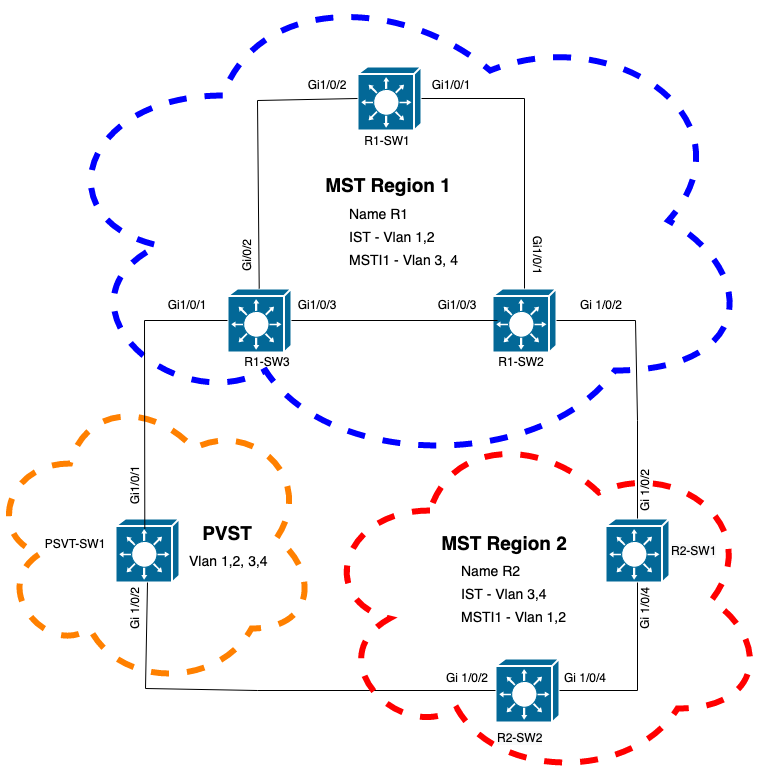
Switch with PVST was added to the network. It interconnects region 1 and 2.
Validation
After PVST switch was connected, boundary port (gi1/0/1) of switch R1-SW3 from region 1 goes to PVST inconsistent and blocks the port.
R1-SW3#show spanning-tree mst

##### MST0    vlans mapped:   1-2,5-4094
Bridge        address f04a.021e.9500  priority      32768 (32768 sysid 0)
Root          address 689e.0ba0.f580  priority      16385 (16384 sysid 1)
              port    Gi1/0/1         path cost     20000
Regional Root this switch
Operational   hello time 2 , forward delay 15, max age 20, txholdcount 6
Configured    hello time 2 , forward delay 15, max age 20, max hops    20

Interface                        Role Sts Cost      Prio.Nbr Type
----------------                 ---- --- --------- -------- --------------------------------
Gi1/0/1                          Root BKN*20000     128.1    P2p Bound(PVST) *PVST_Inc
Gi1/0/2                          Desg FWD 20000     128.2    P2p
Gi1/0/3                          Desg FWD 20000     128.3    P2p

##### MST1    vlans mapped:   3-4
Bridge        address f04a.021e.9500  priority      32769 (32768 sysid 1)
Root          address 3473.2db8.be80  priority      32769 (32768 sysid 1)
              port    Gi1/0/2         cost          20000     rem hops 19

Interface                        Role Sts Cost      Prio.Nbr Type
----------------                 ---- --- --------- -------- --------------------------------
Gi1/0/1                          Mstr BKN*20000     128.1    P2p Bound(PVST) *PVST_Inc
Gi1/0/2                          Root FWD 20000     128.2    P2p
Gi1/0/3                          Altn BLK 20000     128.3    P2p
Note: Similar outputs are observed on R2-SW2 from region 2, which is another boundary port.
.
This happened because any of these rules were broken
- If the root bridge for CIST is within a non-MST region, the spanning-tree priority of VLANs 2 onwards within that domain must be better (lesser) than that of VLAN 1.
- If the root bridge for CIST is within a MST region, VLANs 2 onwards defined in the non-MST domains must have their spanning-tree priorities worse (greater) than that of the CIST root.
Please take a look at the invalid configurations that were set up on the switch to face this issue:
Case 1. PVST switch is the root for VLANS 2-4, however VLANs 2-4 have a worse (greater) priority than VLAN 1. In this case all switches except PVST switch have the default STP priority (32768)
PVST-SW1# show run | inc span
spanning-tree mode pvst
spanning-tree extend system-id
spanning-tree vlan 1 priority 4096    <--
spanning-tree vlan 2-4 priority 16384 <--
spanning-tree mst configuration
Log observed:
%SPANTREE-2-PVSTSIM_FAIL: Blocking root port Gi1/0/1: Inconsitent inferior PVST BPDU received on VLAN 2, claiming root 16386:689e.0ba0.f580
Case 2. PVST switch is not the root for VLANS 1, however VLANs 2-4 have a better(lesser) priority than the root. In this case, root has the default priority 24576. This means the root bridge is not the root for all VLANs
PVST-SW1#show run | inc span
spanning-tree mode pvst
spanning-tree extend system-id
spanning-tree vlan 1 prio 32768       <-- higher priority than the root
spanning-tree vlan 2-4 priority 16384 <--  lower priority than the root
spanning-tree mst configuration
Log observed:
%SPANTREE-2-PVSTSIM_FAIL: Blocking root port Gi1/0/1: Inconsistent inferior PVST BPDU received on VLAN 2, claiming root 40962:689e.0ba0.f580
Once you consider the rules previously mentioned, you can use these valid configurations to delete this issue.
Case 1.
PVST-SW1# show run | inc span
spanning-tree mode pvst
spanning-tree extend system-id
spanning-tree vlan 1 priority 16384  <-- VLAN 1 has a higher priority than all other VLANs
spanning-tree vlan 2-4 priority 4096 <--
spanning-tree mst configuration
Log observed:
%SPANTREE-2-PVSTSIM_OK: PVST Simulation nconsistency cleared on port GigabitEthernet1/0/1.
Case 2.
PVST-SW1#show run | inc span
spanning-tree mode pvst
spanning-tree extend system-id
spanning-tree vlan 1 prio 32768       <-- higher priority than the root
spanning-tree vlan 2-4 priority 40960 <--  higher priority than the root
spanning-tree mst configuration
Log observed:
%SPANTREE-2-PVSTSIM_OK: PVST Simulation nconsistency cleared on port GigabitEthernet1/0/1.
Debugs
Verify the BPDUs with the BPDU debugs if packet capture is not possible.
debug spanning-tree mstp bpdu receive
debug spanning-tree mstp bpdu transmit
Example: For switch 2 in region 2 connected to PVST switch
R2-SW2#debug spanning-tree mstp bpdu receive
MSTP BPDUs RECEIVEd dump debugging is on
R2-SW2#debug spanning-tree mstp bpdu transmit
MSTP BPDUs TRANSMITted dump debugging is on
R2-SW2#debug condition interface gigabitEthernet 1/0/2 <-- interface facing PVST switch

R2-SW2#show logging
! Output omitted for brevity
%LINK-3-UPDOWN: Interface GigabitEthernet1/0/2, changed state to down
%LINK-3-UPDOWN: Interface GigabitEthernet1/0/2, changed state to up
MST[0]:-TX> Gi1/0/2 BPDU Prot:0 Vers:3 Type:2
MST[0]: Role :Desg Flags[P] Age:2 RemHops:19
MST[0]: CIST_root:16385.689e.0ba0.f580 Cost :40000
MST[0]: Reg_root :32768.f04a.0205.d600 Cost :20000
MST[0]: Bridge_ID:32768.a0f8.4910.4780 Port_ID:32770
MST[0]: max_age:20 hello:2 fwdelay:15
MST[0]: V3_len:80 region:R2 rev:1 Num_mrec: 1
MST[1]:-TX> Gi1/0/2 MREC
MST[1]: Role :Desg Flags[MAP] RemHops:20
MST[1]: Root_ID :32769.a0f8.4910.4780 Cost :0
MST[1]: Bridge_ID:32769.a0f8.4910.4780 Port_id:130
%LINEPROTO-5-UPDOWN: Line protocol on Interface GigabitEthernet1/0/2, changed state to up
MST[0]:-TX> Gi1/0/2 BPDU Prot:0 Vers:3 Type:2
MST[0]: Role :Desg Flags[P] Age:2 RemHops:19
MST[0]: CIST_root:16385.689e.0ba0.f580 Cost :40000
MST[0]: Reg_root :32768.f04a.0205.d600 Cost :20000
MST[0]: Bridge_ID:32768.a0f8.4910.4780 Port_ID:32770
MST[0]: max_age:20 hello:2 fwdelay:15
MST[0]: V3_len:80 region:R2 rev:1 Num_mrec: 1
MST[1]:-TX> Gi1/0/2 MREC
MST[1]: Role :Desg Flags[MAP] RemHops:20
MST[1]: Root_ID :32769.a0f8.4910.4780 Cost :0
MST[1]: Bridge_ID:32769.a0f8.4910.4780 Port_id:130
MST[0]:<RX- Gi1/0/2 superior designated BPDU Prot:0 Vers:2 Type:2
MST[0]: Role :Desg Flags[FLTc] Age:0
MST[0]: CIST_root:16385.689e.0ba0.f580 Cost :0
MST[0]: Bridge_ID:16385.689e.0ba0.f580 Port_ID:32770
MST[0]: max_age:20 hello:2 fwdelay:15
P2P Dispute
Topology

Explanation
In this section you can observe a problem with two devices that could not establish an agreement and set the status of the ports properly.
R1-SW1#show spanning-tree mst

##### MST0    vlans mapped:   1-2,5-4094
Bridge        address 3473.2db8.be80  priority      32768 (32768 sysid 0)
Root          address 689e.0ba0.f580  priority      4097  (4096 sysid 1)
              port    Gi1/0/2         path cost     20000
Regional Root address f04a.021e.9500  priority      24576 (24576 sysid 0)
                                      internal cost 20000     rem hops 19
Operational   hello time 2 , forward delay 15, max age 20, txholdcount 6
Configured    hello time 2 , forward delay 15, max age 20, max hops    20

Interface                        Role Sts Cost      Prio.Nbr Type
----------------                 ---- --- --------- -------- --------------------------------
Gi1/0/1                          Desg FWD 20000     128.1    P2p
Gi1/0/2                          Root FWD 20000     128.2    P2p
Gi1/0/4                          Desg BLK 20000     128.2    P2p Dispute

##### MST1    vlans mapped:   3-4
Bridge        address 3473.2db8.be80  priority      32769 (32768 sysid 1)
Root          address f04a.021e.9500  priority      24577 (24576 sysid 1)
              port    Gi1/0/2         cost          20000     rem hops 19

Interface                        Role Sts Cost      Prio.Nbr Type
----------------                 ---- --- --------- -------- --------------------------------
Gi1/0/1                          Desg FWD 20000     128.1    P2p
Gi1/0/2                          Root FWD 20000     128.2    P2p
Gi1/0/4                          Desg BLK 20000     128.2    P2p Dispute
R1-SW1 (root) noticed that a new devices was connected to it. So it sends its BPDU and defines itself as root.
It received a BPDU that specifies that, on the other side on the link, the flags are set as port role: designated, forwarding and learning.
This means that the new switch connected states that has better path to reach the root. However, this is not possible as R1-SW1 is the root and there is no better path to it.
Because both switches could not establish the agreement and set the ports correctly (as both BPDUs show a better path to the root), R1-SW1 assumes that the new switch does not receive its BPDUs and sets the port status to P2P Dispute to avoid unidirectional scenarios that can cause loops.
MST approaches
As observed in this document, MST can be more complicated as long as more switches are added to the network. Due to this, it is important to have different approaches to the same network.
Example:
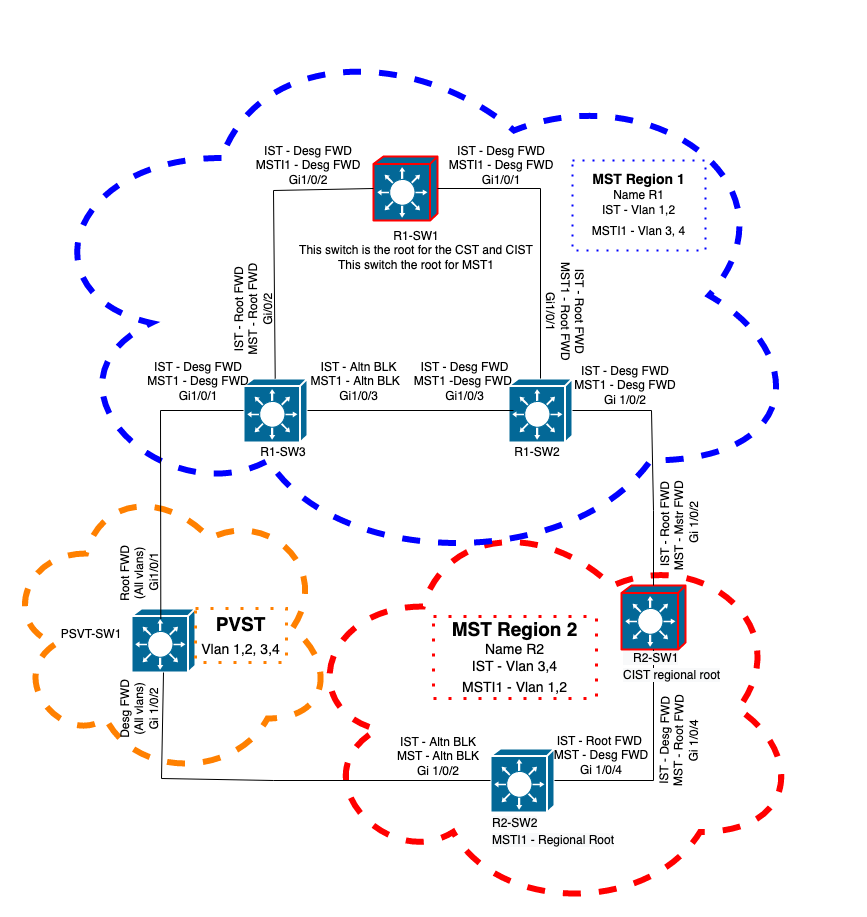
If the issue observed is not within MST region but in a PVST domain, you can have a wider picture and ignore anything inside the MST regions (CST perspective).
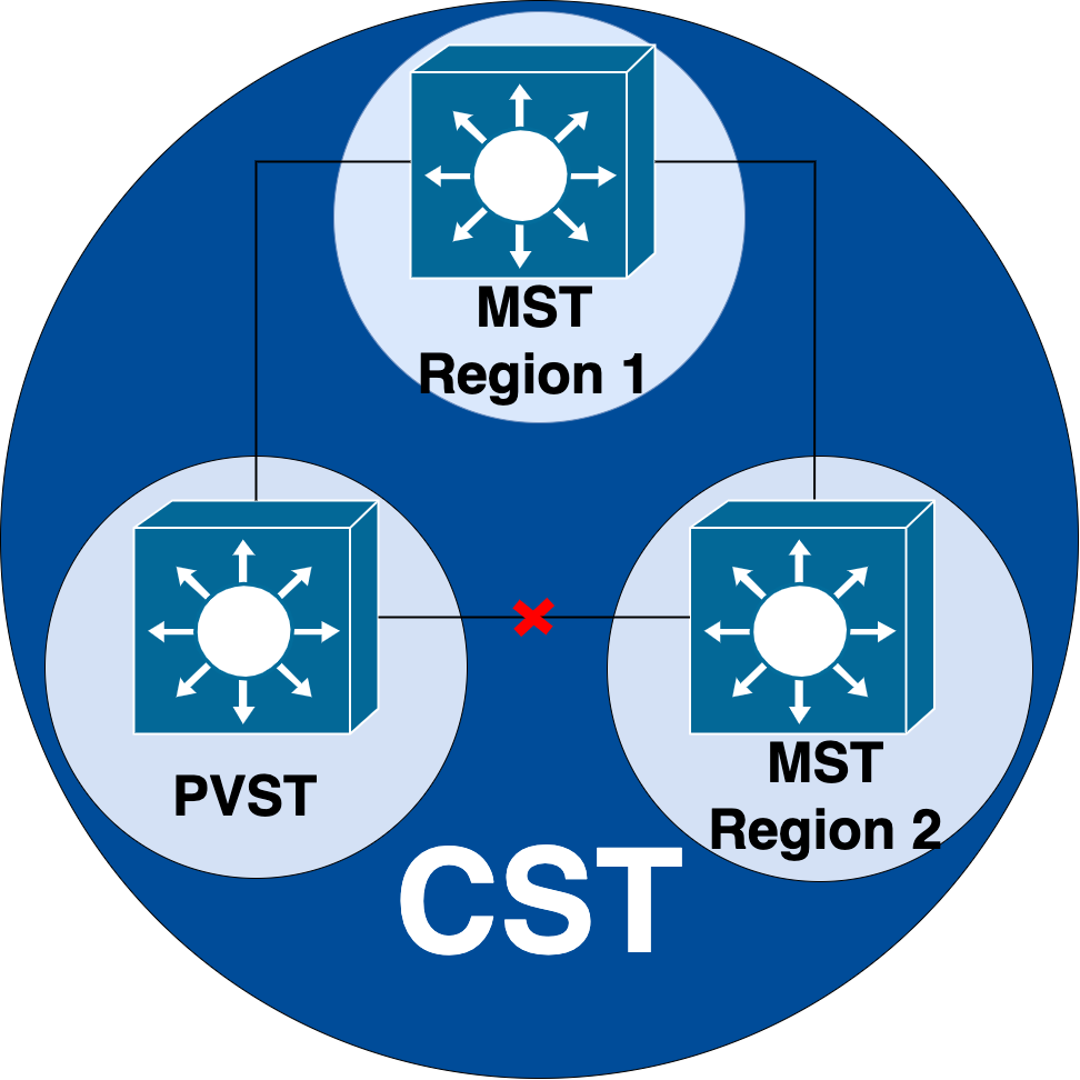
On the other hand if the issue is suspected to be either between MST regions or inside a region, then CIST provides a better perspective.
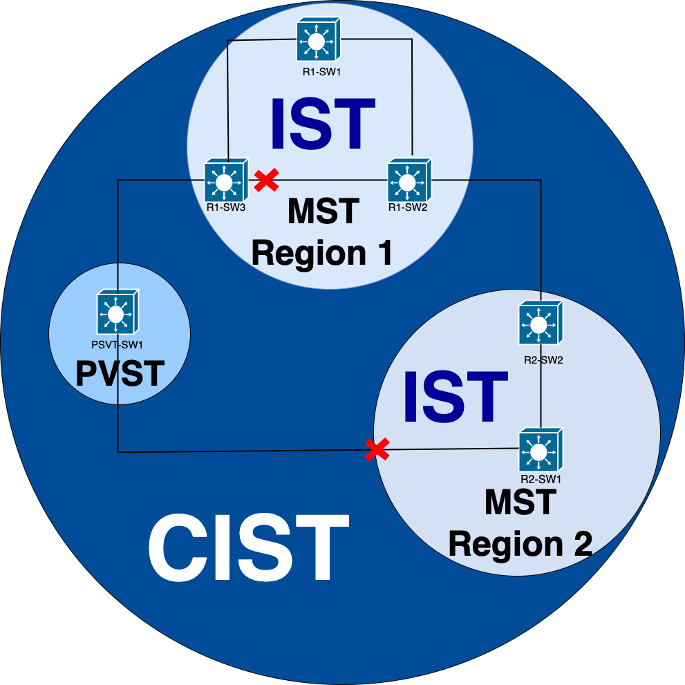
If needed, you can focus on the port roles and status of the switches
Related Information
- Understanding Multiple Spanning Tree Protocol (802.1s)
- Layer 2 Configuration Guide, Cisco IOS XE Amsterdam 17.3.x (Catalyst 9300 Switches)
- Layer 2 and Layer 3 Configuration Guide, Cisco IOS XE Everest 16.5.1a (Catalyst 9300 Switches)
- PVST Simulation n MST Switches
- Cisco bug ID CSCvy02075 - Switch forwards traffic received on ports in blocking BLK state
Revision History
| Revision | Publish Date | Comments |
|---|---|---|
1.0 |
26-Oct-2022 |
Initial Release |
Contributed by Cisco Engineers
- Eduardo Cerezo Alvarez
- Luis Escalante Azcona
Contact Cisco
- Open a Support Case

- (Requires a Cisco Service Contract)
 Feedback