Understanding Issues Related to Inter-VLAN Bridging
Available Languages
Contents
Introduction
Inter-VLAN bridging is the concept of simultaneously bridging multiple VLANs together. Inter-VLAN bridging is occasionally needed in order to bridge non-routable protocols or unsupported routed protocols between multiple VLANs. There are several topology considerations and limitations that must be addressed before you configure inter-VLAN bridging. This document covers these considerations and recommends configuration workarounds.
This list is a brief summary of problems that can arise from inter-VLAN bridging:
-
High CPU utilization on respective inter-VLAN routers
-
Collapsed Spanning-Tree Protocol (STP) where all VLANs belong to a single instance of a STP topology
-
Excessive Layer 2 (L2) flooding of unknown unicast, multicast, and broadcast packets
-
Segmented network topology
A small set of protocols, for example Local-Area Transport (LAT) and Netbeui, cannot be routed. There is a product requirement to allow such protocols to be software bridged between two or more VLANs with bridge groups on a router. When bridging certain protocols together between VLANs, you must provide a mechanism to prevent L2 loop formation when there are multiple connections between the VLANs. STP on the bridge groups involved prevents the formation of loops, but also has these potential problems:
-
Each VLAN's STP could be collapsed into one single STP that encompasses all the VLANs that are bridged together.
-
You lose the ability to place a root bridge on each VLAN. This is needed for proper operation of Uplink Fast.
-
The ability to control at what points in the network links are blocked.
-
It is very likely that a VLAN can become partitioned in the middle of a VLAN. This cuts off access to a portion of a VLAN's router protocols, such as IP. The bridged protocols still work, but take a longer path in this case.
Prerequisites
Requirements
There are no specific requirements for this document.
Components Used
This document is not restricted to specific software and hardware versions.
The information in this document was created from the devices in a specific lab environment. All of the devices used in this document started with a cleared (default) configuration. If your network is live, make sure that you understand the potential impact of any command.
Conventions
Refer to Cisco Technical Tips Conventions for more information on document conventions.
Spanning-Tree Topology Concerns
Inter-VLAN bridging on a router that uses the same STP as the L2 switches results in a single STP instance for every VLAN that is a member of the same bridge. By default, all Catalyst switches and routers run the IEEE STP. Since there is a single instance of STP for all VLANs, several side effects result. For example, a Topology Change Notification (TCN) in one VLAN is propagated to all VLANs. Excessive TCNs can result in excessive unicast flooding. For more information on TCNs, refer to Understanding Spanning-Tree Protocol Topology Changes.
Additional possible side effects are discussed based on this physical topology:
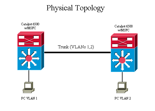
The diagram shown illustrates a physical topology of a typical Layer 3 (L3) network.
Since two VLANs exist, all trunks between the switches and the routers carry both VLAN 1 and VLAN 2. With all Catalyst switches, each VLAN has its own STP topology. For example, the STP for VLAN 1 and VLAN 2 can be illustrated with a logical diagram:
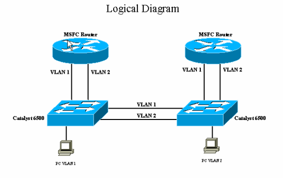
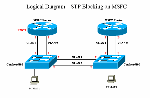
Once the Multilayer Switch Feature Cards (MSFCs) in both Catalyst 6500 are configured for bridging with the IEEE STP, both VLAN 1 and VLAN 2 are bridged together in order to form one single instance of STP. This single instance of STP contains only one STP root. Another way to view the network with the MSFC's bridging is to consider the MSFCs as separate bridges. One instance of STP that involves the MSFCs can result in an undesirable network topology.
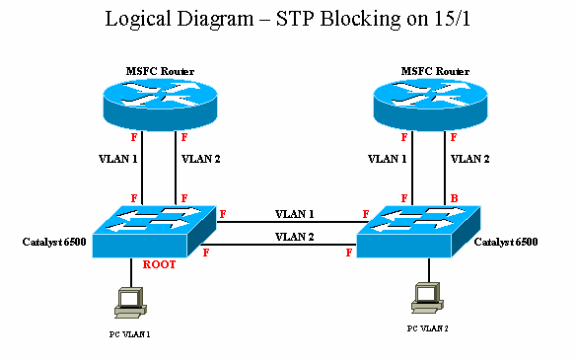
In this diagram, the port that virtually connects the Catalyst 6500 to the MSFC router (port 15/1) is in the STP blocking state for VLAN 2. Since the Catalyst 6500 does not differentiate between a L2 and a L3 packet, all traffic destined for the MSFC is dropped since the port is in the STP blocking state. For example, the PC in VLAN 2, as shown in the diagram, is able to communicate to the MSFC on the switch 1 but not the MSFC on its own switch, switch 2.
In this diagram, the STP PortVLANCost is increased on the trunk between the Catalyst 6500 switches so that the ports that go to the MSFC are in the STP forwarding state. In this situation, the port that goes to switch 1 from switch 2 for VLAN 2 is in the STP blocking state. The STP topology forwards VLAN 2 traffic through the MSFC. Since the MSFC is configured for IP routing, the MSFC only bridges non-IP frames. As a result, the PC in VLAN 2 is not able to communicate to devices in VLAN 2 on the switch 1. This is the case because the port that goes to the switch is in the blocking state, and the MSFC does not bridge any L3 frames.
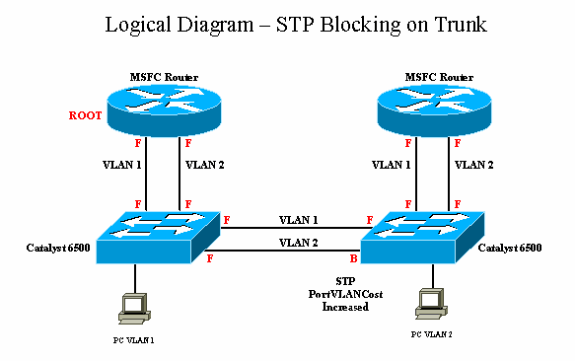
In this diagram, the MSFC blocks on the VLAN 2 connection to switch 2. The MSFC only blocks L2 frames from going out the VLAN 2 connection to the switch and not L3 frames. This is because the MSFC is a L3 device that is able to determine the difference between a frame that needs to be bridged or routed. In this example, there is no network segmentation, and all network traffic flows as desired. Although there is no network segmentation, there is still one single instance of STP for all VLANs.
Recommended Use of Hierarchical Spanning-Tree with VLAN-Bridge Spanning-Tree Protocol
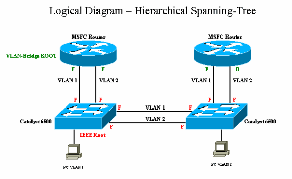
A hierarchical design is the preferred method for how to configure inter-VLAN bridging. A hierarchical design is configured with either the Digital Equipment Corporation (DEC) or VLAN-bridge STP on the MSFC. VLAN-bridge is recommended over DEC. Separate STPs create a two-Layer STP design. In this manner, the individual VLANs maintain their own instance of the IEEE STP. The DEC or VLAN-bridge protocol creates an STP topology that is transparent to the IEEE STP. The protocol also puts the appropriate ports on the MSFC in the blocking state in order to avoid a L2 loop.
The hierarchy is created by the fact that DEC and the VLAN-bridge STP do not propagate IEEE Bridge Port Data Units (BPDUs), but that IEEE STP propagates the DEC and VLAN-Bridge BPDUs.
From this diagram, the MSFCs run VLAN-bridge STP, and the Catalyst 6500 switches run IEEE STP. Since the MSFCs do not pass the IEEE BPDUs from the switch, each VLAN on the switch runs separate instances of IEEE STP. Therefore, all ports on the switch are in a forwarding state. The switches pass the VLAN-bridge BPDUs from the MSFCs. Therefore, a VLAN interface on the non-root MSFC goes to blocking. In this example, there is no network segmentation. All network traffic flows as desired with two different STPs. The MSFC, a L3 device, is able to determine the difference between a frame that needs to bridged or routed.
Spanning-Tree Defaults for VLAN-Bridge, DEC, and IEEE 802.1D Spanning-Tree Protocol
| STP Protocol | Destination Group Address | Data Link Header | Max Age (secs) | Forward Delay (secs) | Hello Time (secs) |
|---|---|---|---|---|---|
| IEEE 802.1D | 01-80-C2-00-00-00 | SAP 0x4242 | 20 | 15 | 2 |
| VLAN-Bridge | 01-00-0C-CD-CD-CE | SNAP cisco, TYPE 0x010c | 30 | 20 | 2 |
| DEC | 09-00-2b-01-00-01 | 0x8038 | 15 | 30 | 1 |
Sample Configuration with VLAN-Bridge Spanning-Tree Protocol on MSFC
Since the VLAN-bridge STP does operate on top of IEEE STP, you must increase the forward delay longer than the time it takes for the IEEE STP to stabilize after a topology change. This ensures that a temporary loop does not occur. In order to support this, the default values for the VLAN-bridge STP parameter are set higher than that of IEEE. An example is shown:
MSFC 1 (Root Bridge)
interface Vlan1
ip address 192.168.75.1 255.255.255.0
bridge-group 1
!
interface Vlan2
ip address 192.168.76.1 255.255.255.0

bridge-group 1
!
bridge 1 protocol vlan-bridge
bridge 1 priority 8192
MSFC 2
interface Vlan1
ip address 192.168.75.2 255.255.255.0
bridge-group 1
!
interface Vlan2
ip address 192.168.76.2 255.255.255.0
bridge-group 1
!
bridge 1 protocol vlan-bridge
Sample Configuration with DEC Spanning-Tree Protocol on MSFC
Since the DEC protocol STP operates on top of IEEE STP, you must increase the forward delay longer than the time it takes for the IEEE STP to stabilize after a topology change. This ensures that a temporary loop does not occur. In order to support this, you must adjust the default values for DEC STP. For DEC STP, the default forward delay is 30. Unlike IEEE or VLAN-bridge STP, DEC STP combines its listen/learn into one timer. Therefore, you must increase the forward delay of DEC to at least 40 seconds on all routers that run DEC STP. An example is shown:
MSFC 1 (Root Bridge)
interface Vlan1
ip address 192.168.75.1 255.255.255.0
bridge-group 1
!
interface Vlan2
ip address 192.168.76.1 255.255.255.0

bridge-group 1
!
bridge 1 protocol dec
bridge 1 priority 8192
bridge 1 forward-time 40
MSFC 2
interface Vlan1
ip address 192.168.75.2 255.255.255.0
bridge-group 1
!
interface Vlan2
ip address 192.168.76.2 255.255.255.0
bridge-group 1
!
bridge 1 protocol dec
bridge 1 forward-time 40
Related Information
Contact Cisco
- Open a Support Case

- (Requires a Cisco Service Contract)
 Feedback