Introduction
This document describes the information contained in the show ip ospf neighbor command output.
Prerequisites
Requirements
Cisco recommends that you have knowledge of these topics:
Components Used
The information in this document is based on the software and hardware versions:
The information in this document was created from the devices in a specific lab environment. All of the devices used in this document started with a cleared (default) configuration. If your network is live, ensure that you understand the potential impact of any command.
Conventions
For more information on document conventions, see the Cisco Technical Tips Conventions.
Background Information
An interface data structure stores information from a network to which it is connected. With this information, an Open Shortest Path First (OSPF) router builds hello packets. These hello packets are exchanged between directly-connected neighbors to learn more about each other. You can use the show ip ospf neighbor command to observe the neighbor data structure. This command displays OSPF-related neighbor information.
Neighbor Data Structure
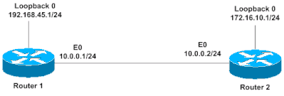
This diagram and show ip ospf neighbor command output are used as an example:

Router2# show ip ospf neighbor

Neighbor ID     Pri    State      Dead Time    Address     Interface
192.168.45.1    1      FULL/DR    00:00:36     10.0.0.1    Ethernet0
The next sections describe the show ip ospf neighbor command output from the previous example.
Neighbor ID
The Neighbor ID is the router ID of the neighbor router. The router ID is the highest IP address or the highest ip address among loopback addresses (if one is configured) on the Cisco router or can be configured manually by "router-id x.x.x.x". In the previous example, Router 1 has a loopback address, 192.168.45.1, which becomes the router ID. Once the router ID is chosen, it cannot changed unless the OSPF process is reset (clear ip ospf process xx) or the router is reloaded. And IP address of router ID does not need to be reachable.
Priority
The Pri field indicates the priority of the neighbor router. The router with the highest priority becomes the designated router (DR). If the priorities are the same, then the router with the highest router ID becomes the DR. By default, priorities are set to 1. A router with a priority of 0 never becomes a DR or a backup designated router (BDR); it is always a DROTHER, that means a router that is neither the DR or the BDR.
State
The State field indicates the functional state of the neighbor router. Refer to OSPF Neighbor States for more information about states. FULL means the router is fully adjacent with its neighbor. The neighbor is the DR, so it is Router 1.
Dead Time
The Dead Time field indicates the amount of time that remains as the router waits to receive an OSPF hello packet from the neighbor before it declares the neighbor is down. On broadcast and point-to-point media, the default dead interval is 40 seconds. On non-broadcast and point-to-multipoint links, the default dead interval is 120 seconds. In the previous example, the Dead Time is 36 seconds before the neighbor 192.168.45.1 is declared down.
Address
The Address field indicates the IP address of the interface to which this neighbor is directly connected. In the case of unnumbered links, this field shows the IP address of the interface to which the neighbor is unnumbered. When OSPF packets are transferred to the neighbor, this address is the destination address. In the previous example the interface IP address of the neighbor is 10.0.0.1.
Interface
The Interface field indicates the interface on which the OSPF neighbor has formed adjacency. In the previous example the neighbor can be reached through Ethernet 0.
Related Information

 Feedback