Why Does the show ip ospf neighbor Command Reveal Neighbors Stuck in Two-Way State?
Available Languages
Contents
Introduction
This document explains why the show ip ospf neighbor command shows neighbors stuck in a two-way state. It also provides configuration tips.
Prerequisites
Requirements
There are no specific requirements for this document.
Components Used
This document is not restricted to specific software and hardware versions.
Conventions
For more information on document conventions, refer to the Cisco Technical Tips Conventions.
How OSPF Forms Its Neighbors
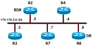
In this topology, all routers are running Open Shortest Path First (OSPF) over the Ethernet network:

This is sample output of the show ip ospf neighbor command on R7 and R8:
R7# show ip ospf neighbor

Neighbor ID     Pri       State           Dead Time   Address         Interface
170.170.3.4       1       2WAY/DROTHER    00:00:34    170.170.3.4     Ethernet0
170.170.3.3       1       2WAY/DROTHER    00:00:34    170.170.3.3     Ethernet0
170.170.3.8       1       FULL/DR         00:00:32    170.170.3.8     Ethernet0
170.170.3.2       1       FULL/BDR        00:00:39    170.170.3.2     Ethernet0

R8# show ip ospf neighbor

Neighbor ID     Pri       State           Dead Time   Address         Interface
170.170.3.4       1       FULL/DROTHER    00:00:37    170.170.3.4     Ethernet0
170.170.3.3       1       FULL/DROTHER    00:00:37    170.170.3.3     Ethernet0
170.170.3.7       1       FULL/DROTHER    00:00:38    170.170.3.7     Ethernet0
170.170.3.2       1       FULL/BDR        00:00:32    170.170.3.2     Ethernet0
Notice that R7 establishes full adjacency only with the Designated Router (DR) and the Backup Designated Router (BDR). All other routers have a two-way adjacency established. This is normal behavior for OSPF.
Whenever a router sees itself in a neighbor hello packet, it confirms bidirectional communication and transitions the neighbor state to two-way. At this point, the routers perform DR and BDR election. Once DR and BDR are elected, a router attempts to form a full adjacency with a neighbor if one of the two routers is the DR or BDR. OSPF routers become fully adjacent with routers with which they have successfully completed the database synchronization process. This is the process by which OSPF routers exchange link-state information to populate their databases with the same information. Again, this database synchronization process is only executed between two routers if one of the two routers is the DR or BDR.
Why Do Routers Only Form Full Adjacencies with the DR or BDR?
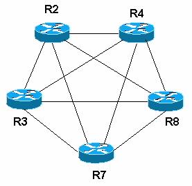
OSPF was designed keeping in focus the requirements of large networks. If all routers formed adjacencies with every other attached router, a large number of link-state advertisements (LSAs) would be sent over the network. If n is the number of routers attached to a broadcast network, there would be n * (n-1) / 2 neighbor pairs. If every pair of neighbors tries to synchronize databases, the amount of LSAs is enormous. In that scenario, a router floods an LSA to all its adjacent neighbors, which in turn floods them to all its adjacent neighbors, and so on. As you can see in this neighbor diagram, if each router has to synchronize databases with each of its neighbors, each router needs to establish four adjacencies:

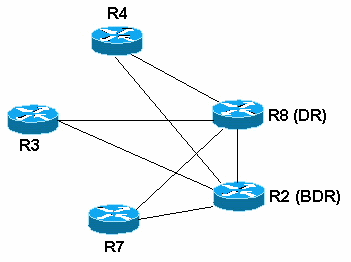
OSPF avoids synchronizing between every pair of routers in the network by using a DR and BDR. In this way, adjacencies are formed only to the DR and BDR, and the number of LSAs sent over the network is reduced. Now, only the DR and BDR have four adjacencies, and all the other routers have two. For this reason, the routers at the hub of the point-to-multipoint network over nonbroadcast multiaccess (NBMA) media should be configured as DR/BDR. Refer to the document Problems with Running OSPF in NBMA Mode over Frame Relay for more information.

Sometimes it is desirable for a router to be configured so that it is not eligible to become the DR or BDR. You can do this by setting the OSPF priority to zero with the ip ospf priority priority# interface subcommand. If two OSPF neighbors both have their OSPF interface priority set to zero, they establish two-way adjacency instead of full adjacency.
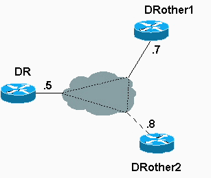
The topology below provides an example. There are three routers connected via Frame Relay. The Frame Relay interfaces are defined as broadcast, but only the router with a connection back to the main network is eligible to be the DR. The other two routers have their interface priorities set to zero, so they are not eligible to become the DR or BDR. Although they do become neighbors, they only reach two-way state.

The neighbor table for this topology looks like this:
DRother1# show ip ospf neighbor
Neighbor ID     Pri   State           Dead Time   Address         Interface
170.170.9.5       1   FULL/DR         00:00:30    170.170.9.5     Serial0.5
170.170.10.8      0   2WAY/DROTHER    00:00:38    170.170.9.8     Serial0.5
DRother1#
Notice that, in the figure above, the DRother1 router establishes a two-way adjacency with the DRother2 router.
Related Information
Revision History
| Revision | Publish Date | Comments |
|---|---|---|
1.0 |
10-Aug-2005 |
Initial Release |
 Feedback