Understand AVB in Catalyst 3K and Catalyst 9000 Series Switches
Available Languages
Download Options
Bias-Free Language
The documentation set for this product strives to use bias-free language. For the purposes of this documentation set, bias-free is defined as language that does not imply discrimination based on age, disability, gender, racial identity, ethnic identity, sexual orientation, socioeconomic status, and intersectionality. Exceptions may be present in the documentation due to language that is hardcoded in the user interfaces of the product software, language used based on RFP documentation, or language that is used by a referenced third-party product. Learn more about how Cisco is using Inclusive Language.
Contents
Introduction
This document describes how to configure and troubleshoot Audio Video Bridging (AVB) in the Catalyst 3650, 3850, 9300, and 9500 platforms.
Background Information
Audio and Video (AV) equipment deployments have traditionally been analog, single-purpose, point-to-point, one-way links. As deployments migrated to digital transmission, they continued to retain the point-to-point, one-way link architecture. This dedicated connection model resulted in a mass of cabling in professional and consumer applications that was hard to manage and operate.
Multiple mechanisms were identified to solve this problem, but all of them were nonstandard, difficult to operate and deploy, or expensive and inflexible. Migration to an Ethernet infrastructure was seen as a means of addressing the needs of professional AV equipment in addition to lowering Total Cost of Ownership (TCO) and enabling transparent integration of new services. However, the deployment mechanism lacked flexibility and interoperability.
To accelerate the adoption of Ethernet-based AV and provide a deployment that is more flexible, IEEE developed the IEEE 802.1 Audio Video Bridging (AVB) standard. This standard defines a mechanism whereby endpoints and the network function as a whole to enable high-quality AV streaming across consumer applications to professional AV deployments over an Ethernet infrastructure.
Hardware/Software Support
AVB is supported on the Cat3K platforms starting from software version Cisco IOS® XE Denali 16.3.x. In Cat9k, the AVB feature was introduced in Fuji-16.8.1a. There have been significant improvements throughout time, so newer software versions include enhancements for the AVB feature.
These platforms support AVB:
| Catalyst 3650/3850 | Catalyst 9300 | Catalyst 9400 | Catalyst 9500 | |
| Supported SKUs/PIDs |
|
|
|
|
Note: At the present time, AVB is supported only on fixed/standalone platforms and not in stacking configuration. Support for modular platforms, like Cat9400, is on the roadmap.
AV Analog Technologies
|
AVB |
DANTE |
CobraNet |
|
|
Standard |
IEEE802.1 (Audio/Video over Ethernet) |
Proprietary (Audio over IP) |
Proprietary (Audio over Ethernet) |
|
Channel Capacity |
Highest channel capacity at >=10Gbps network |
Higher channel capacity at 1Gbps network |
Low channel capacity at 100Mbps network |
|
Clock Synchronization |
IEEE802.1AS gPTP All devices (switch, AVB end point) need to be gPTP capable |
IEEE1588 DANTE enabled devices need to be IEEE1588 capable |
Proprietary |
|
Latency |
<2ms |
<2ms |
<5.33ms High for many applications |
|
Frame/Packet Format |
Layer2 Ethernet frame |
Layer3 IP packet but not routable |
Layer2 Ethernet frame |
|
Configuration & Installation |
Simple (Controller software from different vendors) |
Simple (controller software from DANTE) |
complex |
|
License Fee |
N/A |
Expensive |
Expensive |
|
Network Switch/Router |
Switch needs to support AVB QoS is automatically setup Better QoS feature |
Standard switch QoS is manually setup use of standard Voice over IP (VoIP) Quality of Service (QoS) switch features |
Standard switch QoS is manually setup |
AVB IEEE Standards
IEEE 802.1 Audio Video Bridge (AVB) actually encompasses these four IEEE standards. This means that whenever there is an AVB issue, we have to take into account each of the standards and troubleshoot accordingly:
IEEE802.1AS (gPTP)
- Generalized Precision Time Protocol (gPTP).
- Timing and Synchronization for Time-Sensitive Applications Layer 2 devices.
IEEE802.1Qat (MSRP)
- Multiple Stream Reservation Protocol (MSRP).
- End-to-end traffic admission control system for resource reservation.
IEEE802.1Qav(QoS)
- Forwarding and Queuing for Time-Sensitive Streams (FQTSS).
- AV traffic scheduling and shaping.
IEEE802.1Qak(MVRP)
- Multiple VLAN Registration Protocol.
- Dynamic configuration and sharing of vlan information.
AVB Network Terminology
- AVB Talker: source of AVB stream.
- AVB Bridge/Switch.
- AVB Listener: consumer of AVB stream.
- AVB Stream: stream established between AVB talker and listener.
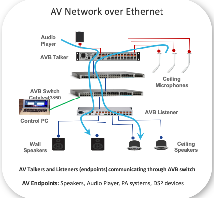
Note: Some AVB end-points can simultaneously act as AVB talker and AVB listener.
AVB Topologies
AVB Domain
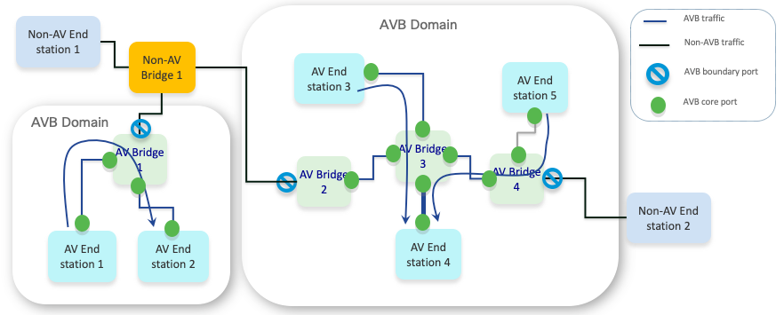
Note: Only one AVB domain is supported per switch.
AVB PTP Domain
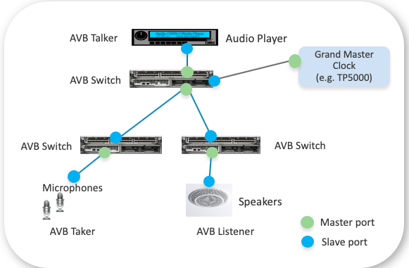
Note: gPTP only supports one domain.
The BMCA is used to select the primary clock on each link, and it ultimately selects the grandmaster clock for the whole gPTP domain. The grandmaster clock is in charge of providing the timing and synchronization for the entire domain. BMCA is used to select the primary and subordinate states of the ports on each link using announce messages. The best clock selected as the primary depends on the quality of the clock (stability) and configurations such as gPTP priority. It runs locally on each port to compare its own local data sets with the received data sets on the announce messages from the neighboring device to determine the best clock on the link.
- Primary: This port is the source of the time on the path.
- Subordinate: This port synchronizes with the device on the path that is in the subordinate state.
A gPTP capable switch determines if a peer is also gPTP capable by measuring peer-to-peer delay which is a delay between directly connected ports with no intervening switch. This delay measurement mechanism uses message types Pdelay_Req, Pdelay_Resp, and Pdelay_Resp_Follow_Up. Based on those message exchanges, the port gPTP capability is decided. Once the primary-subordinate clock hierarchy is established, the clock synchronization process starts.
gPTP is based on IEEE1588v2
- It is similar to BMCA specified in 1588v2, with few simplifications in the state machine
- There is no Pre-primary state (before reaching to Primary state).
- There is no foreign-primary qualification period.
- There is no Uncalibrated state (before reaching to Subordinate state).
|
gPTP |
IEEE1588v2 |
|
|
Transport |
L2 only |
L2/L3 |
|
Mix of systems |
Only time-aware gPTP devices can be in-network |
Can work with a mix of PTP time aware and time unaware devices |
|
Domain |
Only one allowed |
Can be multiple |
|
Best Primary Clock Selection Algorithm |
Simplified state machine |
Pre-primary and Uncalibrated states are present |
|
Types of devices |
AVB endpoints and AVB switches |
Ordinary, Boundary, and Transparent Clocks |
AVB MSRP Domain (QoS)
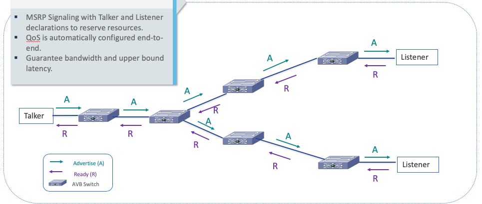
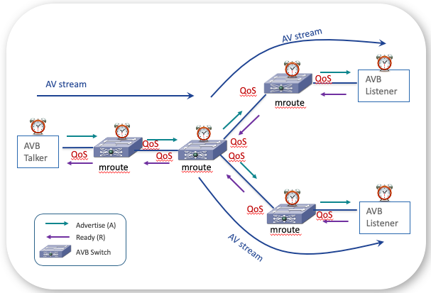
A Talker declaration is forwarded over output ports that can potentially lead to the destination MAC address of the reservation. Listener declarations are only propagated to the port with the associated Talker declaration (that is... based on the matching stream ID). If there is no associated Talker declaration registered on any switch port then Listener declaration is not propagated.
Note: MSRP-aware switches automatically generate de-registration of stale registrations to tear down the AVB sessions.
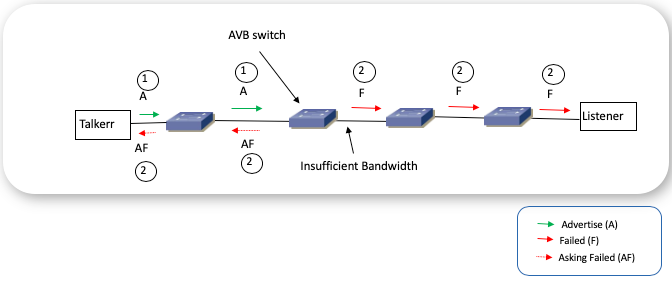
MSRP – Reservation Failure during Advertise Registration
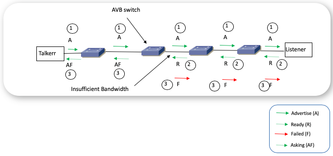
MSRP – Reservation Failure during Ready Registration
MSRP – Talkers States
Talker Advertise: An advertisement for a Stream that has not encountered any bandwidth or other network constraints along the network path from the Talker.
Talker Failed: An advertisement for a Stream that is not available to the Listener because of bandwidth constraints or other limitations somewhere along the path from the Talker.
MSRP – Listener States
Ready: This subtype indicates that there is at least one Listener that both intends to listen and has successfully reserved resources and that there are no Listeners that intend to listen but were unable to reserve resources.
Ready Failed: This subtype indicates that there is at least one Listener that both intends to listen and has successfully reserved resources, but at least one other Listener intends to listen but was unable to reserve resources.
Asking Failed: This subtype indicates that there is at least one Listener that intends to listen but was unable to reserve resources, but there were no Listeners that both intended to listen and were successful at reserving resources.
AVB Architecture – QoS Class of Traffic
8Q policy is supported. Cat3K/Cat9K does not support per-port ingress queueing. Internal queues are fine-tuned for AVB to provide end-to-end preferential treatment for SR class traffic within the switch (low latency).
Control traffic examples: OAM, Signaling, Network Control, InterNetwork Control
| Stream Reservation (SR) Class A | Stream Reservation (SR) Class B | Control Traffic | VoIP |
|
Highest priority worst-case latency 2 milliseconds COS 3 |
2nd Highest priority worst-case latency 50 milliseconds COS 2 |
COS 6,7 |
COS 5 |
| Multimedia | Transactional Data | Bulk/Scavenger Data | Best Effort |
|
COS 4 |
COS - |
COS 1 |
COS 0 |
IEEE802.1Qav – QoS Ingress Remarking
- AVB stream data packets are classified into SRP traffic classes using the PCP (priority control point) of the incoming frame.
- To protect reserved flows, an AVB switch cannot allow a non-AVB participant port to forward best-effort traffic into an SRP class queue.
- To accomplish this protection, ingress re-marking must be done on all non-AVB participant ports (SRP domain Edge ports) to change incoming PCP matching any SRP class into a best-effort PCP.
- Any time any port's SRP Domain status changes (edge vs core) this re-marking must be added or removed.
IEEE802.1Qav – QoS Egress Queue
- SR class traffic is mapped onto egress priority queue that supports credit-based traffic shaper algorithm
- Dynamic configuration of Egress Shaper Rate (for bandwidth reservation) on per class and per port basis for AVB core ports
- For Cat3k, switch generated control traffic (that is... gPTP, MSRP) is in best effort queue in 16.3.1 release. They are in the priority queue in the 16.3.2 release and onwards.
AVB Architecture – Bandwidth Allocation Design
- A maximum of 75% of bandwidth is allocated for SR Class A + SR Class B.
- SR Class A reserves up to 75% of bandwidth.
- SR Class B reserves bandwidth that is not used by SR Class A.
- Bandwidth is allocated on a first come first served basis for AV stream.
- Hardware credit-based shaper to schedule AVB traffic evenly.
AVB MVRP Domain
What is MVRP?
- Multiple VLAN Registration Protocol (MVRP) is an application based on MRP (Multiple Registration Protocol) that supports dynamic registration and de-registration of VLANs on ports in a VLAN-bridged network. It uses MRP to declare the Attributes to be registered in a database on each port of each bridge in a bridged network. The actual Attribute used by MVRP is the VLAN ID. Stations or configured Bridge Ports make (withdraw) declarations if they do (not) need to receive frames for a given VLAN ID. If a VLAN ID is registered on a Bridge Port by MVRP, the Bridge knows that frames for that VLAN ID must be transmitted on that Bridge Port.
- MVRP allows AVB endpoints to make declarations if they need to receive frames for a given VLAN ID.
- MVRP allows AVB endpoints to withdraw declarations if they do not need to receive frames for a given VLAN ID.
When MVRP is Enabled on the Switch
- MVRP VLAN declaration from the end-point triggers VLAN creation on the switches.
- There are three different MVRP registration modes for a port:
Normal - VLANs are dynamically registered/de-registered based on device declarations. This is the default mode for the ports when MVRP is globally enabled (mvrp registration normal).
Fixed - Port ignores all MVRP declarations. VLANs that are statically configured are not dynamically pruned by MVRP. This mode can be configured on a per-port basis on interfaces that are connected to network devices that are not MVRP-aware (mvrp registration fixed).
Forbidden - Port ignores all incoming MVRP messages and prunes VLANs (mvrp registration forbidden).
Note: VTP must be in disabled mode or transparent mode for MVRP to work.
Note: MVRP works with Declaration and Registration events in a bidirectional way, which means that end-points and neighboring bridges in that domain would also need to be MVRP-aware if this feature gets enabled on one of the devices, otherwise the bridge where MVRP is enabled can prune some of the VLANs if it doesn't receive a Declaration/Registration for them, which can lead to potential connectivity issues.
When MVRP is not enabled on the Switch
Manually configure the switches in trunk mode allowing all range of VLANS that are expected to be used by the AVB streams.
AVB Flow – Put Together
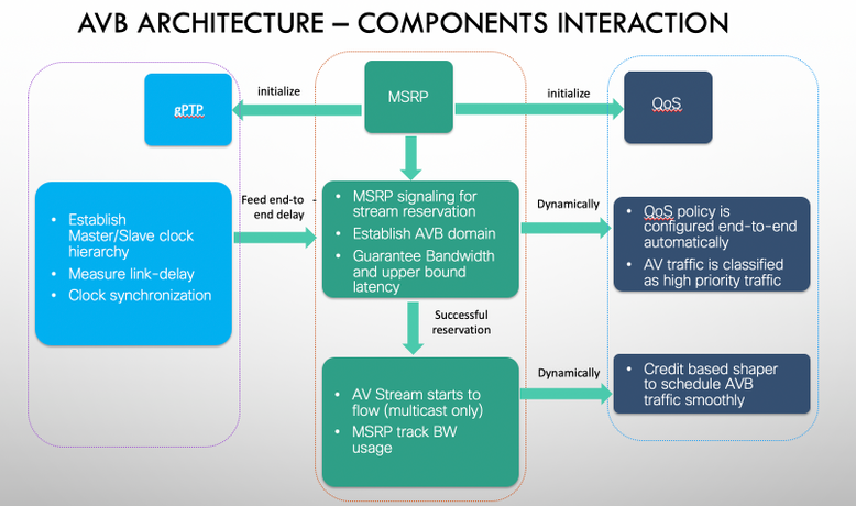
- MSRP initializes gPTP for time synchronization.
- MSRP initializes QoS policy on AVB switchport.
- MSRP Signaling with Talker and Listener declarations to check resources. Guarantee bandwidth and upper bound latency.
- QoS (shaper) is dynamically adjusted. Up to 75% of bandwidth is allocated for SR Class A + SR Class B.
- MSRP adds layer2 multicast entry.
- AV stream starts flowing.
AVB Components Interaction
Troubleshoot AVB in Cat3k and Cat9k Switches
AVB Configuration
How to configure AVB
Step 1. Enable the AVB feature and its corresponding VLAN:
Cat3850# configure terminal
Cat3850(config)# avb
Cat3850(config)# vlan 2
Cat3850(config)# end
Note: Standard VLAN-ID used by AVB is VLAN 2. A different VLAN-ID can be set in the switch for the AVB VLAN using cli avb vlan <vlan-id>. This configuration serves the function of specifying the VLAN to which AVB specific QoS settings are applied via MSRP. If there is a need to use a non-standard VLAN (other than VLAN 2 which is the default) that needs to be set on AVB end-device controller as well so that the AVB end-devices declare to the switch the correct VLAN that is desired for AVB, otherwise, the AVB end-devices can advertise their streams on a different VLAN than the one configured on the switch.
Step 2. Configure the switch interfaces along the AVB connectivity path as dot1q trunk ports:
Cat3850# configure terminal
Cat3850(config)# interface GigabitEthernet1/0/3
Cat3850(config-if)# switchport mode trunk
Cat3850(config-if)# end
Cat3850#
Step 3 (Optional). Enable MVRP on the switch to enable dynamic VLAN propagation.
Cat3850# configure terminal
Cat3850(config)# mvrp global
Cat3850(config)# vtp mode transparent
Cat3850(config)# mvrp vlan create
Cat3850(config)# end
Cat3850#
Step 4 (Optional). Adjust PTP priority on the switch.
Cat3850#configure terminal
Cat3850(config)# ptp priority1 <0-255>
Cat3850(config)# ptp priority2 <0-255>
Cat3850(config)# end
Cat3850#
Configuration Automatically Added by MSRP
Support for hierarchical QoS for AVB was introduced on Cisco XE Denali 16.3.2. AVB Hierarchical QoS policy is a two-level Parent-Child Policy. AVB Parent policy segregates audio, video traffic streams (SR-Class A ,SR-Class B) and Network Control packets from standard best-effort ethernet traffic (Non-SR) and manages streams accordingly.
Note: QoS policies for AVB are automatically created and controlled by MSRP.
Note: The end-user has complete control over child policies that contain Non-SR class attributes and can modify only these child policies, that is...: policy-map AVB-Output-Child-Policy and policy-map AVB-Input-Child-Policy. AVB HQoS child policy configurations are retained even after reload.
Different types of Ingress Policies
Core port for SR Class A and Boundary port for SR Class B (This means that on this port, MSRP received an advertisement only for a class A stream, so all traffic for B is remarked to COS 0, whereas marking for class A stream is preserved).
interface GigabitEthernet1/0/3
 service-policy input AVB-Input-Policy-Remark-B
 service-policy output AVB-Output-Policy-Gi1/0/3

policy-map AVB-Input-Policy-Remark-B
 class AVB-SR-B-CLASS                     <<< Parent Policy dynamycally generated (not user editable)
  set cos 0 (set 0 for boundary & SR class B PCP value for core port)
 class class-default
  service-policy AVB-Input-Child-Policy   <<< Child Policy (user editable)
Core port for SR Class B and Boundary port for SR Class A (This means that on this port, MSRP received an advertisement only for a class B stream, so all traffic for A is remarked to COS 0, whereas marking for class B stream is preserved).
interface GigabitEthernet1/0/4
 service-policy input AVB-Input-Policy-Remark-A
 service-policy output AVB-Output-Policy-Gi1/0/4

policy-map AVB-Input-Policy-Remark-A
 class AVB-SR-A-CLASS                     <<< Parent Policy dynamycally generated (not user editable)
  set cos 0 (set 0 for boundary & SR class A PCP value for core port)
 class class-default
  service-policy AVB-Input-Child-Policy   <<< Child Policy (user editable)
Core port for SR Class A and SR Class B (This means that on this port, MSRP received advertisements for class A and B streams, so the ingress marking for both stream types is preserved).
interface GigabitEthernet1/0/2
 service-policy input AVB-Input-Policy-Remark-None
 service-policy output AVB-Output-Policy-Gi1/0/2

policy-map AVB-Input-Policy-Remark-None
 class class-default
  service-policy AVB-Input-Child-Policy   <<< Child Policy (user editable)
Boundary port for SR Class A and SR Class B (This means that on this port, MSRP did not receive advertisements for any streams, neither class A nor class B streams, so the ingress marking for both stream types is remarked to COS 0).
interface GigabitEthernet1/0/1
 service-policy input AVB-Input-Policy-Remark-AB
 service-policy output AVB-Output-Policy-Gi1/0/1

policy-map AVB-Input-Policy-Remark-AB
 class AVB-SR-A-CLASS                     <<< Parent Policy dynamycally generated (not user editable)
  set cos 0 (set 0 for boundary & SR class A PCP value for core port)
 class AVB-SR-B-CLASS                     <<< Parent Policy dynamycally generated (not user editable)
  set cos 0 (set 0 for boundary & SR class B PCP value for core port)
 class class-default
  service-policy AVB-Input-Child-Policy   <<< Child Policy (user editable)
Input Child Policy (User editable)
policy-map AVB-Input-Child-Policy
class VOIP-DATA-CLASS
 set dscp EF
class MULTIMEDIA-CONF-CLASS
 set dscp AF41
class BULK-DATA-CLASS
 set dscp AF11
class TRANSACTIONAL-DATA-CLASS
 set dscp AF21
class SCAVENGER-DATA-CLASS
 set dscp CS1
class SIGNALING-CLASS
 set dscp CS3
class class-default
 set dscp default
Different types of Egress Policies
The egress policy is also dynamically configured by MSRP on a port basis. MSRP can dynamically reserve a max. of 75% of the port bandwidth for classes A and B. The other 15% is statically reserved for control management traffic and the rest can be assigned on-demand to the different traffic types defined on the AVB-Output-Child-Policy:
policy-map AVB-Output-Policy-Gix/y/z
 class AVB-SR-A-CLASS
  priority level 1 (Shaper value based on stream registration)
 class AVB-SR-B-CLASS
  priority level 2 (Shaper value based on stream registration)
 class CONTROL-MGMT-QUEUE
  priority level 3 percent 15
 class class-default
  bandwidth remaining percent 100
  queue-buffers ratio 80
  service-policy AVB-Output-Child-Policy  <<< Child Policy (user editable)


policy-map AVB-Output-Child-Policy
 class VOIP-PRIORITY-QUEUE
  bandwidth remaining percent 30
  queue-buffers ratio 10
 class MULTIMEDIA-CONFERENCING-STREAMING-QUEUE
  bandwidth remaining percent 15
  queue-limit dscp AF41 percent 80
  queue-limit dscp AF31 percent 80
  queue-limit dscp AF42 percent 90
  queue-limit dscp AF32 percent 90
  queue-buffers ratio 10
 class TRANSACTIONAL-DATA-QUEUE
  bandwidth remaining percent 15
  queue-limit dscp AF21 percent 80
  queue-limit dscp AF22 percent 90
  queue-buffers ratio 10
 class BULK-SCAVENGER-DATA-QUEUE
  bandwidth remaining percent 15
  queue-limit dscp AF11 percent 80
  queue-limit dscp AF12 percent 90
  queue-limit dscp CS1 percent 80
  queue-buffers ratio 15
 class class-default
  bandwidth remaining percent 25
  queue-buffers ratio 25
In this example, Gi1/0/6 is a Core port for SR Class A and Boundary port for SR Class B (this means that on this port, we are only receiving advertisements for class A streams). The bandwidth allocated for AV streams is limited to a maximum 75 percent of the total port bandwidth. Since in this case, the port is auto-negotiating a link speed of 1 Gbps, then max 75% of this bandwidth - 750 Mbps - can be reserved for class A and B streams. In this case. MSRP dynamically reserved 71% for class-A (approx 701 Mbps) and 0% for class-B.
However, when we check the actual QoS-Policy attached to the interface, we can notice that from that 75% of reservable BW, 71% was effectively assigned to Class-A (priority level 1) but in reality, also a small portion of the BW - 1% - was assigned to Class-B (priority level 2). As expected, 15% was assigned to control-mgmt traffic (priority level 3), and the remaining bandwidth got assigned to the user-editable egress child policy:
show msrp port interface Gi1/0/6
Port: Gi1/0/6    Admin: admin up    Oper: up
  MTU: 1500    Bandwidth: 1000000 Kbit/s    DLY: 0 us   mode: Trunk
  gPTP status: Enabled, asCapable
    Residence delay: 20000 ns
    Peer delay: 84 ns (Updated Wed Nov 18 17:35:18.823)
  AVB readyness state: Ready
    Per-class value              Class-A     Class-B
    -------------------------------------------------------
    Tx srClassVID                2           2
    Rx srClassVID                2           0
    Domain State                 Core        Boundary
    VLAN STP State               FWD         FWD
    Reservable BW (Kbit/s)       750000      0
    Reserved BW (Kbit/s)         701504      0
    Applied QOS BW (percent)     71          0


show policy-map interface Gi1/0/6

  Service-policy output: AVB-Output-Policy-Gi1/0/6

  <snip>

    Class-map: AVB-SR-CLASS-A (match-any)
      0 packets
      Match: cos  3
      Priority: 701504 kbps, burst bytes 17537600,   <<< 71% of the reservable BW
      Priority Level: 1

    Class-map: AVB-SR-CLASS-B (match-any)
      0 packets
      Match: cos  2
      Priority: 10000 kbps, burst bytes 250000,   <<< 1% of the reservable BW
      Priority Level: 2
    Class-map: AVB-CONTROL-MGMT-QUEUE (match-any)
      0 packets
      Match: ip dscp cs2 (16)
        0 packets, 0 bytes
        5 minute rate 0 bps
      Match: ip dscp cs3 (24)
        0 packets, 0 bytes
        5 minute rate 0 bps
      Match: ip dscp cs6 (48)
        0 packets, 0 bytes
        5 minute rate 0 bps
      Match: ip dscp cs7 (56)
        0 packets, 0 bytes
        5 minute rate 0 bps
      Match: ip precedence 6
        0 packets, 0 bytes
        5 minute rate 0 bps
      Match: ip precedence 7
        0 packets, 0 bytes
        5 minute rate 0 bps
      Match: ip precedence 3
        0 packets, 0 bytes
        5 minute rate 0 bps
      Match: ip precedence 2
        0 packets, 0 bytes
        5 minute rate 0 bps
      Match: cos  6
        0 packets, 0 bytes
        5 minute rate 0 bps
      Match: cos  7
        0 packets, 0 bytes
        5 minute rate 0 bps
      Priority: 15% (150000 kbps), burst bytes 3750000,  <<<< 15% of the total BW
      Priority Level: 3

    Class-map: class-default (match-any)
      0 packets
      Match: any
      Queueing

      (total drops) 0
      (bytes output) 81167770686
      bandwidth remaining 100%    <<< all remaining BW got assigned to child policy
      queue-buffers ratio 70

      Service-policy : AVB-Output-Child-Policy
     <snip>
Verify AVB Works Properly
You have to break down troubleshooting into five pieces:
1. Did we configure AVB properly in all the switches involved?
2. Check AVB
3. Check MSRP (QoS)
4. Check gPTP
5. Check MVRP
AVB Considerations
<< show avb domain >>
- Number and type of ports for each AVB Stream (Class-A and Class-B)
- Core for a certain class means that a stream advertisement for that SR class was received on that port.
- Boundary means that an advertisement for that SR class was not received on that port.
- Not asCapable means that PTP is not supported on that port
- A port can be Core for both classes at the same time.
- PCP = QoS Priority Code Point
- VID = VLAN-ID used for AVB
Switch#show avb domain
AVB Class-A
    Priority Code Point     : 3
    VLAN                    : 2
    Core ports              : 2
    Boundary ports          : 31

AVB Class-B
    Priority Code Point     : 2
    VLAN                    : 2
    Core ports              : 0
    Boundary ports          : 33

--------------------------------------------------------------------------------
Interface    State       Delay    PCP  VID  Information
--------------------------------------------------------------------------------
     Te1/0/1          up    300ns
   Class-  A        core             3    2
   Class-  B    boundary             0    0
----
     Te1/0/2          up      N/A                    Port is not asCapable
----
     Te1/0/3          up    284ns
   Class-  A        core             3    2
   Class-  B    boundary             0    0
----
     Te1/0/4        down      N/A                        Oper state not up
----
     Te1/0/5        down      N/A                        Oper state not up
----
     Te1/0/6        down      N/A                        Oper state not up
----
<< show avb stream >>
- Relevant info about the stream (stream ID, actual bandwidth, Incoming and Outgoing interfaces).
- A port can simultaneously be sender for some streams and receiver for some others, depending on the AV-endpoint connected to that port.
------------------ show avb stream ------------------


Stream ID:     0090.5E15.965A:65434    Incoming Interface:    Te1/0/1
    Destination  : 91E0.F000.3470   <<<< AVB works with layer-2 multicast (least-significant bit of the first octet is on)
    Class        : A
    Rank         : 1
    Bandwidth    : 8192 Kbit/s

    Outgoing Interfaces:
    ----------------------------------------------------------------------------
    Interface         State      Time of Last Update         Information
    ----------------------------------------------------------------------------
    Te1/0/3           Ready      Wed Jun 13 16:32:36.224

Stream ID:     0090.5E15.96D5:65436    Incoming Interface:    Te1/0/3
    Destination  : 91E0.F000.0770
    Class        : A
    Rank         : 1
    Bandwidth    : 5120 Kbit/s

    Outgoing Interfaces:
    ----------------------------------------------------------------------------
    Interface         State      Time of Last Update         Information
    ----------------------------------------------------------------------------
    Te1/0/1           Ready      Wed Jun 13 16:28:45.114
MSRP Considerations
<< show msrp streams >>
<< show msrp streams brief >>
<< show msrp streams stream-id # >>
- Relevant info for each MSRP phase during MSRP reservation for each stream (Advertise, Fail, Ready, ReadyFail, and so on.).
------------------ show msrp streams ------------------

Legend: R = Registered, D = Declared.
--------------------------------------------------------------------------------
Stream ID                       Talker                  Listener
                          Advertise    Fail       Ready     ReadyFail   AskFail
                           R | D      R | D      R | D      R | D      R | D
--------------------------------------------------------------------------------
0090.5E15.965A:65434        1 | 1      0 | 0      1 | 1      0 | 0      0 | 0
0090.5E15.96D5:65436        1 | 1      0 | 0      1 | 1      0 | 0      0 | 0
0090.5E15.96D5:65534        1 | 1      0 | 0      1 | 1      0 | 0      0 | 0


------------------ show msrp streams brief ------------------

Legend: R = Registered, D = Declared.
--------------------------------------------------------------------------------
Stream ID              Destination         Bandwidth   Talkers   Listeners  Fail
                       Address              (Kbit/s)    R | D      R | D
--------------------------------------------------------------------------------
0090.5E15.965A:65434   91E0.F000.3470     8192          1 | 1      1 | 1    No
0090.5E15.96D5:65436   91E0.F000.0770     5120          1 | 1      1 | 1    No
0090.5E15.96D5:65534   91E0.F000.0770     3584          1 | 1      1 | 1    No
0090.5E1A.33E2:65534   0000.0000.0000     0             0 | 0      1 | 0    Yes <<< Listener is requesting for this stream but no Talker transmit


show msrp streams stream-id 65534 <<< non-working one (ASK Failed).
Legend: R = Registered, D = Declared.
--------------------------------------------------------------------------------
Stream ID                       Talker                  Listener
                          Advertise    Fail       Ready     ReadyFail   AskFail
                           R | D      R | D      R | D      R | D      R | D
--------------------------------------------------------------------------------
0090.5E1A.33E2:65534        0 | 0      0 | 0      0 | 0      0 | 0      1 | 0  <<< Listener request for the stream, but such stream is not transmitted by any talker
<snip>
<< show msrp port bandwidth >>
- How much of the 75% reservable bandwidth that can be used by AV-Streams was actually assigned to the port based on the MSRP negotiation (in this case only 2% for SR-Class A stream).
------------------ show msrp port bandwidth ------------------

--------------------------------------------------------------------------------
Ethernet      Capacity       Assigned       Available       Reserved
Interface     (Kbit/s)        A | B          A | B           A | B
--------------------------------------------------------------------------------
Te1/0/1     1000000          75 | 0         73 | 73          2 | 0
Te1/0/2     1000000          75 | 0         75 | 75          0 | 0
Te1/0/3     1000000          75 | 0         73 | 73          2 | 0
Te1/0/4     1000000          75 | 0         75 | 75          0 | 0
<< show msrp port interface >>
Switch# sh msrp port int te1/0/1
Port: Te1/0/1    Admin: admin up    Oper: up
  MTU: 1500    Bandwidth: 1000000 Kbit/s    DLY: 0 us   mode: Trunk
  gPTP status: Enabled, asCapable
    Residence delay: 20000 ns
    Peer delay: 295 ns (Updated Thu Apr 27 16:49:05.574)
  AVB readyness state: Ready
    Per-class value              Class-A     Class-B
    -------------------------------------------------------
    Tx srClassVID                2           2
    Rx srClassVID                2           0
    Domain State                 Core        Boundary
    VLAN STP State               FWD         FWD
    Reservable BW (Kbit/s)       750000      0
    Reserved BW (Kbit/s)         14720       0
    Applied QOS BW (percent)     2           0


Switch# show msrp port interface gi 1/0/40 det
Port: Gi1/0/40 Admin: admin down Oper: down
Intf handle: 0x30 Intf index: 0x30
Location: 1/40, Handle: 0x1001000100000027
MTU: 1500 Bandwidth: 1000000 Kbit/s DLY: 0 us mode: Other
LastRxMAC: 0:90:5E:1A:F5:92
gPTP status: Enabled
AVB readyness state: Oper state not up
Per-class value Class-A Class-B
    -------------------------------------------------------
    Tx srClassVID                2           2
    Rx srClassVID                2           0
    Domain State                 Boundary    Boundary   <<< Interface is Down hence Boundary.
    VLAN STP State               BLK         BLK
    Reservable BW (Kbit/s)       750000      0
    Reserved BW (Kbit/s)         0           0
    Applied QOS BW (percent)     0           0
  Registered Talker: count 0
  Declared Talker: count 0
  Registered Listener: count 1
      Handle 0x1001000100001F97
          Registered Listener, Listener Fail
          Stream: 0090.5E1B.048D:65534, handle 1001000100001F96
          Port handle 0x1001000100000027, vlan: 0
                MRP: 0/0/60207669/0/0
<< show tech msrp >>
- To collect all relevant MSRP outputs
Switch#show tech msrp

------------------ show clock ------------------

*10:32:56.410 UTC Thu Jun 13 2017

------------------ show version ------------------


Cisco IOS Software [Denali], Catalyst L3 Switch Software (CAT3K_CAA-UNIVERSALK9-M), Version 16.3.2, RELEASE SOFTWARE (fc4)
Technical Support: http://www.cisco.com/techsupport
Copyright (c) 1986-2016 by Cisco Systems, Inc.
Compiled Tue 08-Nov-16 17:31 by mcpre


Cisco IOS-XE software, Copyright (c) 2005-2016 by cisco Systems, Inc.
All rights reserved.  Certain components of Cisco IOS-XE software are
licensed under the GNU General Public License ("GPL") Version 2.0.  The
software code licensed under GPL Version 2.0 is free software that comes
with ABSOLUTELY NO WARRANTY.  You can redistribute and/or modify such
GPL code under the terms of GPL Version 2.0.  For more details, see the
documentation or "License Notice" file accompanying the IOS-XE software,
or the applicable URL provided on the flyer accompanying the IOS-XE
software.
<snip>
QoS Considerations
- AVB networks guarantee bandwidth and minimum bounded latency for time-sensitive audio and video streams.
- AVB defines Class A and Class B as the time-sensitive streams, based on the worst-case latency targets of the traffic from talker to listener (the priority code points to map the traffic to the specific stream, COS 3 for Class A and COS 2 for Class B).
- The latency targets for the two streams are listed here:
- SR-Class A: 2ms
- SR-Class B: 50ms
Note: The sum of the worst-case latency contributions per hop results in an overall end-to-end latency of 2 ms or less for SR-Class A and 50ms or less for SR-Class B. A typical AVB deployment of 7 hops from talker to listener meets these latency requirements.
Note: gPTP is not supported for speeds of 100Mbps or less on mGig platforms. Reason: 100Mbps speed introduces a jitter of more than 50ms.
PTP Considerations
- Check where the Grandmaster Clock is located and run (be aware that Grandmaster clock can be an external device):
<< show ptp brief >>
- In this output Master means that this port is the source of the time (Primary) and Subordinate means that it is receiving the timing from the other end (Faulty means that nothing is connected or the other end does not support PTP). If all the AVB-ports on a switch are Primary, then the switch is the Grandmaster Clock.
Switch#show ptp brief
Interface                       Domain    PTP State
FortyGigabitEthernet1/1/1       0         FAULTY
FortyGigabitEthernet1/1/2       0         FAULTY
TenGigabitEthernet1/0/1         0         MASTER
TenGigabitEthernet1/0/2         0         MASTER
TenGigabitEthernet1/0/3         0         MASTER
TenGigabitEthernet1/0/4         0         FAULTY
TenGigabitEthernet1/0/5         0         FAULTY
TenGigabitEthernet1/0/6         0         FAULTY
TenGigabitEthernet1/0/7         0         FAULTY
TenGigabitEthernet1/0/8         0         FAULTY
TenGigabitEthernet1/0/9         0         FAULTY
<snip>
<< show ptp clock >>
- This output provides Local PTP info.
Switch#show ptp clock
 PTP CLOCK INFO
  PTP Device Type: Boundary clock
  PTP Device Profile: IEEE 802/1AS Profile
  Clock Identity: 0x2C:86:D2:FF:ED:AD:A6:0
  Clock Domain: 0
  Number of PTP ports: 34
  PTP Packet priority: 4
  Priority1: 2
  Priority2: 2
  Clock Quality:
        Class: 248
        Accuracy: Unknown
        Offset (log variance): 16640
  Offset From Master(ns): 0
  Mean Path Delay(ns): 0
  Steps Removed: 0
<< show ptp parent >>
- Provides info about Grandmaster clock identity:
Switch# show ptp parent
 PTP PARENT PROPERTIES
  Parent Clock:
  Parent Clock Identity: 0x2C:86:D2:FF:ED:AD:A6:0
  Parent Port Number: 0
  Observed Parent Offset (log variance): 16640
  Observed Parent Clock Phase Change Rate: N/A

  Grandmaster Clock:
  Grandmaster Clock Identity: 0x2C:86:D2:FF:ED:AD:A6:0  <<< Local switch is the Grandmaster Clock of the domain
  Grandmaster Clock Quality:
        Class: 248
        Accuracy: Unknown
        Offset (log variance): 16640
        Priority1: 2
        Priority2: 2
<< show ptp port >>
<< show platform software fed switch active ptp interface >>
- These outputs display detailed PTP port info, like Neighbor Propagation Delay.
- At first, the Neighbor Propagation Delay is checked, and only if this value is within the permissible range, the link is promoted as AVB capable and the rest of the processes would follow. Else, the link is set to not asCapable state and AVB won’t work.
- Based on network design/requirement the neighbor propagation delay can be manually configured:
ptp neighbor-propagation-delay-threshold
Non-Working Port:
switch#show ptp port gi1/0/32
PTP PORT DATASET: GigabitEthernet1/0/32
  Port identity: clock identity: 0xB0:90:7E:FF:FE:28:3C:0
  Port identity: port number: 32
  PTP version: 2
  Port state: DISABLED
  Delay request interval(log mean): 0
  Announce receipt time out: 3
  Neighbor prop delay(ns): -10900200825022  <<< The is an erroneous reading. Default to 800ns.
  Announce interval(log mean): 0
  Sync interval(log mean): -3
  Delay Mechanism: Peer to Peer
  Peer delay request interval(log mean): 0
  Sync fault limit: 500000000


switch# show platform software fed switch active ptp interface gi1/0/32
Displaying port data for if_id 28
=======================================
Port Mac Address B0:90:7E:28:3C:20
Port Clock Identity B0:90:7E:FF:FE:28:3C:00
Port number 32
PTP Version 2
domain_value 0
Profile Type: : DOT1AS
dot1as capable: FALSE
sync_recpt_timeout_time_interval 375000000 nanoseconds
sync_interval 125000000 nanoseconds
compute_neighbor_rate_ratio: TRUE
neighbor_rate_ratio 0.999968
compute_neighbor_prop_delay: TRUE
neighbor_prop_delay 9223079830310536030 nanoseconds <<< Error reading
port_enabled: TRUE
ptt_port_enabled: TRUE
current_log_pdelay_req_interval 0
pdelay_req_interval 1000000000 nanoseconds
allowed_pdelay_lost_responses 3
is_measuring_delay : TRUE
neighbor_prop_delay_threshold 800 nanoseconds
Port state: : DISABLED
sync_seq_num 29999
num sync messages transmitted  903660
num followup messages transmitted  903628
num sync messages received  0
num followup messages received  0
num pdelay requests transmitted  161245
num pdelay responses received 161245
num pdelay followup responses received  161245
num pdelay requests received  161283
num pdelay responses transmitted  161283
num pdelay followup responses transmitted  160704


Working Port:
switch#show ptp port gi1/0/7
PTP PORT DATASET: GigabitEthernet1/0/7
Port identity: clock identity: 0xB0:90:7E:FF:FE:28:3C:0
Port identity: port number: 7
PTP version: 2
PTP port number: 7
PTP slot number: 1
Port state: MASTER
Delay request interval(log mean): 0
Announce receipt time out: 3
Neighbor prop delay(ns): 154
Announce interval(log mean): 0
Sync interval(log mean): -3
Delay Mechanism: Peer to Peer
Peer delay request interval(log mean): -3
Sync fault limit: 500000000

switch#sh platform software fed switch active ptp interface gi1/0/7
Displaying port data for if_id f
=======================================
Port Mac Address B0:90:7E:28:3C:07
Port Clock Identity B0:90:7E:FF:FE:28:3C:00
Port number 7
PTP Version 2
domain_value 0
Profile Type: : DOT1AS
dot1as capable: TRUE
sync_recpt_timeout_time_interval 375000000 nanoseconds
sync_interval 125000000 nanoseconds
compute_neighbor_rate_ratio: TRUE
neighbor_rate_ratio 1.000000
compute_neighbor_prop_delay: TRUE
neighbor_prop_delay 146 nanoseconds
port_enabled: TRUE
ptt_port_enabled: TRUE
current_log_pdelay_req_interval -3
pdelay_req_interval 0 nanoseconds
allowed_pdelay_lost_responses 3
is_measuring_delay : TRUE
neighbor_prop_delay_threshold 800 nanoseconds
Port state: : MASTER
sync_seq_num 41619
num sync messages transmitted 2748392
num followup messages transmitted 2748387
num sync messages received 0
num followup messages received 35
num pdelay requests transmitted 2746974
num pdelay responses received 2746927
num pdelay followup responses received 2746926
num pdelay requests received 2746348
num pdelay responses transmitted 2746348
num pdelay followup responses transmitted 2746345
MVRP Considerations
- MVRP is optional. Manual configuration of VLANS on the switches is sufficient for AVB (ports in trunk mode, vlan 2 is normally used for AVB).
- If MVRP is enabled on the switch, then VTP must be in disabled or transparent mode for MVRP to work.
!
mvrp global
mvrp vlan create
!
!
<snip>
!
!
vlan 2
avb
!
!
vtp mode transparent
<< show mvrp interface >>
- In this example, we manually configured vlan 17 on switch1. We can see that right after that, we start sending MVRP declarations for that vlan over the trunk interface Gi1/0/1, which is connected to Te1/0/2 of switch2:
switch1(config)#vlan 17
switch1(config-vlan)#exit

switch1(config)#interface vlan 17
switch1(config-if)#

*Nov 10 10:48:40.155: %LINEPROTO-5-UPDOWN: Line protocol on Interface Vlan17, changed state to up >>> configured vlan with interface.

switch1(config)#do sh mvrp interface Gi1/0/1
Port         Status    Registrar State
Gi1/0/1      on              normal

Port         Join Timeout       Leave Timeout   Leaveall Timeout   Periodic
                                                                   Timeout
Gi1/0/1      20                 60              1000               100

Port         Vlans Declared   >>> Switch is sending Declarations for VLAN 17 over Gi1/0/1
Gi1/0/1      1,8,17

Port         Vlans Registered >>> MVRP Registration available only for VLAN 1 and 8
Gi1/0/1      1,8

Port         Vlans Registered and in Spanning Tree Forwarding State
Gi1/0/1      1,8


switch1(config)#do show interfaces trunk

Port        Mode             Encapsulation  Status        Native vlan
Gi1/0/1     on               802.1q         trunking      1

Port        Vlans allowed on trunk
Gi1/0/1     1-4094

Port        Vlans allowed and active in management domain
Gi1/0/1     1-2,8,17,21-33,35-62,64-72,74-82,84-86,88-91,94-95,97-110,112-198,531-544,800-802,900-1000

Port        Vlans in spanning tree forwarding state and not pruned
Gi1/0/1     1,8 >>> Vlan 17 is Pruned because we have not received any Declaration from the neighboring device, hence this vlan is not registered in MVRP yet.
- In the outputs shown previously, we can see that switch1 is sending MVRP Declarations for the recently created vlan 17, but the vlan is not registered in MVRP for that interface yet, hence it is being pruned on that port by the switch. The Registration event for that vlan hasn't been completed on switch1 likely because the neighboring device switch2 is not sending MVRP Declarations for that vlan (either because that vlan doesn't exist on that device or because switch2 is not running MVRP).
- In our case, the neighboring device switch2 is already running MVRP, but SVI for vlan 17 was not created there yet, so it was not sending MVRP Declarations for that vlan. As soon as we created SVI for vlan 17 on switch2, it started sending Declarations for this vlan and the vlan got registered in MVRP on switch1
### switch2

switch2(config)#do show mvrp interface Te1/0/2
Port         Status    Registrar State
Te1/0/2      on              normal

Port         Join Timeout       Leave Timeout   Leaveall Timeout   Periodic
                                                                   Timeout
Te1/0/2      20                 60              1000               100

Port         Vlans Declared
Te1/0/2      1,8    >>> we are not sending Declarations for vlan 17 to switch1

Port         Vlans Registered
Te1/0/2      1,8,17 >>> we see the vlan getting registered and hence in forwarding state on this switch.

Port         Vlans Registered and in Spanning Tree Forwarding State
Te1/0/2      1,8,17


switch2(config)#do show interfaces trunk

Port        Mode             Encapsulation  Status        Native vlan
Te1/0/2     on               802.1q         trunking      1

Port        Vlans allowed on trunk
Te1/0/2     1-4094

Port        Vlans allowed and active in management domain
Te1/0/2     1,8,17

Port        Vlans in spanning tree forwarding state and not pruned
Te1/0/2     1,8,17  >>> vlan 17 is in forwarding state on switch2

switch2(config)#int vlan 17
switch2(config-if)#
*Nov 10 11:32:55.539: %LINEPROTO-5-UPDOWN: Line protocol on Interface Vlan17, changed state to up


### switch1

switch1(config)#do sh mvrp interface Gi1/0/1

Port         Status    Registrar State
Gi1/0/1      on              normal

Port         Join Timeout       Leave Timeout   Leaveall Timeout   Periodic
                                                                   Timeout
Gi1/0/1      20                 60              1000               100

Port         Vlans Declared
Gi1/0/1      1,8,17

Port         Vlans Registered
Gi1/0/1      1,8,17  >>> vlan 17 is now registered on switch1

Port         Vlans Registered and in Spanning Tree Forwarding State
Gi1/0/1      1,8,17  >>> and in FWD state


switch1(config)#do show interfaces trunk

Port        Mode             Encapsulation  Status        Native vlan
Gi1/0/1     on               802.1q         trunking      1

Port        Vlans allowed on trunk
Gi1/0/1     1-4094

Port        Vlans allowed and active in management domain
Gi1/0/1     1-2,8,17,21-33,35-62,64-72,74-82,84-86,88-91,94-95,97-110,112-198,531-544,800-802,900-1000

Port        Vlans in spanning tree forwarding state and not pruned
Gi1/0/1     1,8,17    >>> vlan 17 is in FWD state and no longer pruned
Tip: If the neighboring device does not run or support MVRP, then, on the switch that is already running MVRP, you can configure this line on the port where the neighbor that doesn't support MVRP is connected: 'mvrp registration fixed'. This config ignores all MVRP declarations on that port and all VLANs that are statically configured on that switch won't be dynamically pruned by MVRP on that interface.
List of Commands
--- AVB verification commands ---
#gptp
show ptp brief
show ptp clock
show ptp parent
show ptp port <int_name>
show platform software fed switch active ptp interface <int_name>

#avb
show avb domain
show avb stream

#msrp
show msrp streams
show msrp streams brief
show msrp streams detail
show msrp streams stream-id <stream-id>
show msrp port bandwidth
show msrp port interface <int_name>
show tech msrp

#mvrp
show mvrp summary
show mvrp interface <int_name>

#QoS
show policy-map interface <int_name>
show interface <int_name> counter errors
show platform hardware fed switch active qos queue config interface <int_name>
show platform hardware fed switch active qos queue stats interface <int_name>
show platform hardware fed switch active fwd-asic resource tcam utilization
show tech qos

!!! Starting from Cisco IOS XE Denali 16.3.2, 'show running-config interface' command does not display any details of the AVB policy attached.
!!! You must use 'show policy-map interface' command to display all the details of the AVB policy attached to that port.

#FED QoS
show platform software fed switch active qos policy summary
show platform software fed switch active qos policy target interface <int_name>
Related Information
- Cisco Audio Video Bridging Design and Deployment for Enterprise Networks (White Paper)
https://www.cisco.com/c/dam/en/us/products/collateral/switches/catalyst-3850-series-switches/white-paper-c11-736890.pdf - Audio Video Bridging on Cat3K Switches
https://www.cisco.com/c/dam/en/us/products/collateral/switches/q-and-a-c67-737896.pdf - AVB Product Page
https://www.cisco.com/c/en/us/products/switches/avb.html - AVB Configuration Guide on Denali 16.3.x
https://www.cisco.com/c/en/us/td/docs/switches/lan/catalyst3650/software/release/16-3/configuration_guide/b_163_consolidated_3650_cg/b_163_consolidated_3650_cg_chapter_010.html - AVB Configuration Guide on Everest 16.6.x
https://www.cisco.com/c/en/us/td/docs/switches/lan/catalyst3850/software/release/16-6/configuration_guide/avb/b_166_avb_3850_cg/b_165_avb_3850_cg_chapter_00.html - AVB Configuration Guide on Fuji 16.9.x
https://www.cisco.com/c/en/us/td/docs/switches/lan/catalyst9300/software/release/16-9/configuration_guide/avb/b_169_avb_9300_cg/audio_video___bridging.html - AVB Configuration Guide on Gibraltar 16.10.x
https://www.cisco.com/c/en/us/td/docs/switches/lan/catalyst9300/software/release/16-10/configuration_guide/avb/b_1610_avb_9300_cg/audio_video___bridging.html - Biamp Systems - Enabling AVB on Cisco Catalyst Switches
https://support.biamp.com/Tesira/AVB/Enabling_AVB_on_Cisco_Catalyst_Switches
Revision History
| Revision | Publish Date | Comments |
|---|---|---|
2.0 |
15-Oct-2021 |
Added some additional styling fixes |
1.0 |
14-Dec-2020 |
Initial Release |
Contributed by
- Eduardo CruzCisco Professional Services
- Luis Fernando PastranaCisco TAC Engineer
Contact Cisco
- Open a Support Case

- (Requires a Cisco Service Contract)
 Feedback