Multicast forwarding in vPC based on location of the source
Available Languages
Download Options
Bias-Free Language
The documentation set for this product strives to use bias-free language. For the purposes of this documentation set, bias-free is defined as language that does not imply discrimination based on age, disability, gender, racial identity, ethnic identity, sexual orientation, socioeconomic status, and intersectionality. Exceptions may be present in the documentation due to language that is hardcoded in the user interfaces of the product software, language used based on RFP documentation, or language that is used by a referenced third-party product. Learn more about how Cisco is using Inclusive Language.
Contents
Introduction
This document explains various scenarios of multicast forwarding when a source is positioned in a vPC environment
Prerequisites
Requirements
Cisco recommends that you have knowledge of these topics:
Components Used
The information in this document is based on these software and hardware versions:
- Nexus 7000 running software 8.1(1)
-
Supervisor N7K-SUP2E
-
Line card N7K-M348XP-25L
The information in this document was created from the devices in a specific lab environment. All of the devices used in this document started with a cleared (default) configuration. If your network is live, make sure that you understand the potential impact of any command.
Topology

Configure
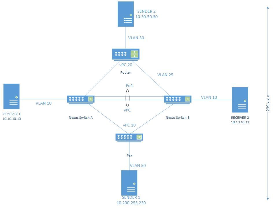
Switch A and Switch B are VPC peers.
Sender1 is connected in VLAN 50 (10.200.255.230, 239.3.0.2)
Sender2 is connected to L3_swicth/Router in VLAN 30 and known to vpc-peer via VLAN 25 (10.30.30.30, 239.3.0.2)
Receiver1 is connected on an orphan port 4/1 on Switch A
Receiver2 is connected on an orphan port 4/1 on Switch B
Switch A

Ip route 10.30.30.0/24 10.25.25.250
ip pim rp-address 10.25.25.250 group-list 224.0.0.0/4
ip pim ssm range 232.0.0.0/8
ip pim pre-build-spt

Switch B

Ip route 10.30.30.0/24 10.25.25.250
ip pim rp-address 10.25.25.250 group-list 224.0.0.0/4
ip pim ssm range 232.0.0.0/8
ip pim pre-build-spt
Source connected to vPC VLAN
Receiver1 is continuously requesting for the traffic from group 239.3.0.2 and register the (*, G) on Switch A in VLAN 10.
Switch B adds the same entry with the help of CFS. The receiver can be connected on orphan or vpc member port in VPC vlan.
Since Sender1 is connected to VPC VLAN traffic sent to VLAN 50 and both Nexus devices adds OIF entry (S, G).
Both Devices forwards the traffic based on PIM internal forwarding algorithm as the sender is connected to the vPC VLAN directly.
Switch A# show ip pim internal vpc rpf-source
PIM vPC RPF-Source Cache for Context "default" - Chassis Role Secondary
Source: 10.200.255.230
  Pref/Metric: 0/0
  Ref count: 1
  In MRIB: yes
  Is (*,G) rpf: no
  Source role: Primary
  Forwarding state: Win-force (forwarding)
Switch B# show ip pim internal vpc rpf-source
PIM vPC RPF-Source Cache for Context "default" - Chassis Role Secondary
Source: 10.200.255.230
  Pref/Metric: 0/0
  Ref count: 1
  In MRIB: yes
  Is (*,G) rpf: no
  Source role: secondary
  Forwarding state: Win-force (forwarding)
OIF also populated to both the vpc peers.
Switch A# show ip mroute

(*, 232.0.0.0/8), uptime: 02:16:01, pim ip
  Incoming interface: Null, RPF nbr: 0.0.0.0
  Outgoing interface list: (count: 0)

(*, 239.3.0.2/32), uptime: 01:42:35, igmp ip pim
  Incoming interface: Vlan10, RPF nbr: 10.10.10.251
  Outgoing interface list: (count: 1)
    Vlan10, uptime: 01:42:35, igmp, (RPF)

(10.200.255.230/32, 239.3.0.2/32), uptime: 02:15:57, ip pim mrib
  Incoming interface: Vlan50, RPF nbr: 10.200.255.230
  Outgoing interface list: (count: 1)
    Vlan10, uptime: 01:42:35, mrib
Switch B# sh ip mroute

(*, 232.0.0.0/8), uptime: 02:03:17, pim ip
  Incoming interface: Null, RPF nbr: 0.0.0.0
  Outgoing interface list: (count: 0)

(*, 239.3.0.2/32), uptime: 01:31:59, igmp ip pim
  Incoming interface: Null, RPF nbr: 0.0.0.0
  Outgoing interface list: (count: 1)
    Vlan10, uptime: 01:31:59, igmp

(10.200.255.230/32, 239.3.0.2/32), uptime: 02:03:13, ip pim mrib
  Incoming interface: Vlan50, RPF nbr: 10.200.255.230
  Outgoing interface list: (count: 1)
    Vlan10, uptime: 01:31:59, mrib
Receiver1 gets the stream and as soon as Receiver2 request for the same group, Receiver 2 also starts receiving it.
Source connected to L3 router
Sender2 is sending the stream to the FHRP which is L3_swicth in VLAN 30, which is also working as the RP in this case.
L3_swicth will forward the stream towards the VPC peer on VPC VLAN 25. This traffic is treated as multicast over L3 and both VPC peer will build the (S, G).
Receiver1 and Receiver2 request for the multicast stream and (*, G) created on both vpc peers.
Since Sender2 stream is received over PIM on SVI 25 and not directly on VPC SVI, Only one device (DR) will be forwarding the traffic based on the PIM internal forwarding algorithm as the Sender 2 is not directly on VPC SVI.
Switch A# show ip pim internal vpc rpf-source
Source: 10.30.30.30
  Pref/Metric: 1/0
  Ref count: 1
  In MRIB: yes
  Is (*,G) rpf: no
  Source role: primary
  Forwarding state: Tie (forwarding)
  MRIB Forwarding state: forwarding
Switch B# sh ip pim internal vpc rpf-source
Source: 10.30.30.30
  Pref/Metric: 1/0
  Ref count: 1
  In MRIB: yes
  Is (*,G) rpf: no
  Source role: secondary
  Forwarding state: Tie (not forwarding)
  MRIB Forwarding state: not forwarding
Hence OIF populated only on DR.
Switch A# show ip mroute
IP Multicast Routing Table for VRF "default"

(*, 232.0.0.0/8), uptime: 02:37:29, pim ip
  Incoming interface: Null, RPF nbr: 0.0.0.0
  Outgoing interface list: (count: 0)

(*, 239.3.0.2/32), uptime: 02:37:26, igmp ip pim
  Incoming interface: Vlan25, RPF nbr: 10.25.25.250
  Outgoing interface list: (count: 1)
    Vlan10, uptime: 02:37:26, igmp

(10.30.30.30/32, 239.3.0.2/32), uptime: 02:37:26, ip mrib pim
  Incoming interface: Vlan25, RPF nbr: 10.25.25.250
  Outgoing interface list: (count: 1)
    Vlan10, uptime: 02:37:26, mrib
Switch B# show ip mroute
(*, 232.0.0.0/8), uptime: 02:38:15, pim ip
  Incoming interface: Null, RPF nbr: 0.0.0.0
  Outgoing interface list: (count: 0)

(*, 239.3.0.2/32), uptime: 02:38:15, igmp ip pim
  Incoming interface: Vlan25, RPF nbr: 10.25.25.250
  Outgoing interface list: (count: 1)
    Vlan10, uptime: 02:38:15, igmp

(10.30.30.30/32, 239.3.0.2/32), uptime: 02:38:15, ip mrib pim
  Incoming interface: Vlan25, RPF nbr: 10.25.25.250
  Outgoing interface list: (count: 1) >>>>>> no OIF
In this case as Receiver1 gets the stream and Receiver 2 will never get the stream due to missing OIF on Switch B.
Source connected between different VRF

Multicast traffic is forwarded to only one receiver in vlan10 connected to primary vpc peer while the receiver connected to the secondary peer does not receive it.
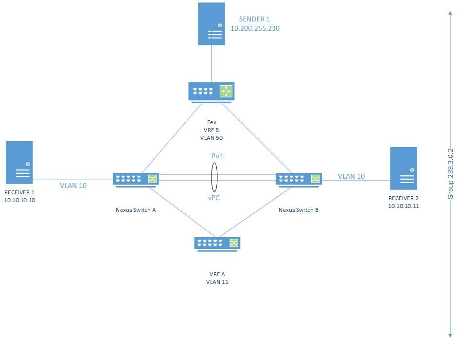
- Multicast sent to fex on vlan 50 (vpc vlan), in this case, both Switch A and Switch B have OIF for VRF B as the source is directly connected to it and it is in vpc vlan.
- This traffic is forwarded to vlan 51 towards the VRF A located in a different VDC and sent to RP.
- This VDC has vlan 11 in VRF A and vlan 51 in default VRF.
- The traffic is now sent to Switch A vlan 11 which is in VRF A.
- Only one of Switch A/Switch B have OIF for the VRF A due to the same limitation mentioned in the Sender 2 connected to L3 router case.
- The Receiver1 connected to the Switch A with OIF gets the Multicast stream.
This is a design limitation.
VPC peer can only have OIF installed in both the switches if the traffic is directly forwarded by the sender in VPC VLAN and not by the PIM.
Hence OIF installed in VRF A as Sender directly connected to the VRF A, but not in VRF B as it is connected via PIM.
To get the OIF on both VPC peers, the sender should directly be connected to the vpc VLAN.
This feature will be implemented later on as part of "L3 over VPC" feature
Reference
Known Defects
Contributed by Cisco Engineers
- Lovkesh SharmaTAC Engineer
Contact Cisco
- Open a Support Case

- (Requires a Cisco Service Contract)
 Feedback