Introduction
This document describes the importance of Border Gateway Protocol (BGP) Weight path attribute in network failover scenarios.
Prerequisites
Requirements
Cisco recommends that you have knowledge of these topics:
- Border Gateway Protocol (BGP)
- Routing Protocols Redistribution
- Cisco Router that runs Cisco IOS®
Components Used
The information in this document is based on a Cisco Router with Cisco IOS® version 15.6(2)
The information in this document was created from the devices in a specific lab environment. All of the devices used in this document started with a cleared (default) configuration. If your network is live, ensure that you understand the potential impact of any command.
Background Information
BGP is commonly used to advertise the network prefixes to the Wan Area Network (WAN) once received via an Interior Gateway protocol (IGP) from the Lan Area Network (LAN) and vice versa. Without the correct configuration in place, BGP can fail to restore the original routing path over the WAN after the network recovers from a link failure.
Routers deployed in failover scenarios can have routes stuck which can cause a redirect of the traffic over the backup path post a failure and recovery network event. This can happen due to the nature of the BGP Weight path attribute.
After a network failure occurs (usually with the WAN link) the network can converge and use the available backup path received via the IGP.
However, upon recovery of the primary path, the Router can still use the backup path and not restore the original route over the WAN link.
Consequences like asymmetric and sub-optimal routing paths can be seen.
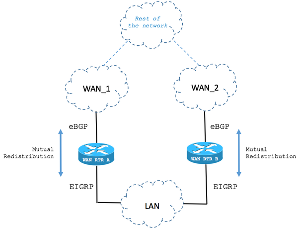
In redundancy scenarios with two WAN Routers, these can run BGP to exchange network prefixes with the WAN. An IGP like Enhanced Interior Gateway Routing Protocol (EIGRP) can be used to exchange network prefixes with the LAN network devices. Mutual Redistribution between these protocols is usually necessary to accomplish full network connectivity.
Note: This document makes use of the terms prefix and route interchangeably.
The high level design of this can be seen in the next topology:

BGP Weight Path Attribute Set in Locally Originated Routes
The next scenario describes the behavior of the BGP Weight Path attribute in fail over cases.
Step 1. Route is received via BGP.
As shown in the image, the Router named WAN RTR receives the 192.168.1.0/24 network via BGP.
With an Administrative Distance (AD) of 20, the route is installed it in the Routing Table.

BGP table:
| WAN_RTR |
WAN_RTR#show ip bgp
<snip>
     Network          Next Hop            Metric LocPrf Weight Path
 *>  192.168.1.0      10.1.2.2                 0             0 2 i
|
Routing Table shows the route installed by BGP:
| WAN_RTR |
WAN_RTR#show ip route
<snip>
B     192.168.1.0/24 [20/0] via 10.1.2.2, 00:00:42
|
Step 2. Route is received via EIGRP.
The BGP session goes down due to link failure. By network convergence, the same route 192.168.1.0/24 is now received via EIGRP.

The key point is that BGP can advertise or redistribute EIGRP routes (with the help of the next Router configuration). If that is the case, the EIGRP route is now added to the BGP table.
Note: BGP Weight path attribute is set to 32768 by default when the Router locally originates network prefixes.
BGP configuration:
| WAN_RTR |
WAN_RTR#show running-config | begin router bgp
<snip>
router bgp 1
 redistribute eigrp 1
 neighbor 10.1.2.2 remote-as 2
!
|
Note: The BGP command network 192.168.1.0 mask 255.255.255.0 can show the same results.
BGP Table:
| WAN_RTR |
WAN_RTR#show ip bgp
<snip>

     Network          Next Hop            Metric LocPrf Weight Path
 *>  192.168.1.0      10.1.3.3            156160         32768 ?
|
Routing Table shows the route installed by EIGRP:
| WAN_RTR |
WAN_RTR#show ip route
<snip>

D     192.168.1.0/24 [90/156160] via 10.1.3.3, 00:00:02, FastEthernet0/1
WAN_RTR#
|
Step 3. Route received via BGP again.
With the EIGRP route now redistributed into BGP and after the original route is received via the BGP once again, there are now 2 entries for the 192.168.1.0/24 network in the BGP table.

BGP Table:
| WAN_RTR |
WAN_RTR#show ip bgp
<snip>

     Network          Next Hop            Metric LocPrf Weight Path
 *   192.168.1.0      10.1.2.2                 0             0 2 i
 *>                   10.1.3.3            156160         32768 ?
|
In the BGP table:
- The entry created in step 2 by the EIGRP route redistributed into BGP can still be seen.
- The original route is added back by means of the BGP session re-established.
From the BGP best path selection point of view:
- The value of the Weight path attribute of the EIGRP route redistributed into BGP is set to 32768 since it is locally originated in the Router from the BGP point of view.
- The value of the Weight path attribute of the original route received via the BGP session with the WAN is 0.
- The first route has the highest Weight and it is therefore elected as best in the BGP table.
- This causes the Routing Table not to converge back to the original state and keep the EIGRP route entry.
Note: The BGP Weight Path attribute is the first path attribute BGP checks in the election of the best path in the BGP table on Cisco IOS Routers. BGP prefers the path for the entry with the highest Weight. Weight is a Cisco-specific parameter and it is only locally significant in the Router where it is configured. More information via BGP Best Path Selection Algorithm.
Routing Table:
| WAN_RTR |
WAN_RTR#show ip route
<snip>
D     192.168.1.0/24 [90/156160] via 10.1.3.3, 00:08:55, FastEthernet0/1
|
Modify the BGP Weight Path Attribute
The default value of the BGP Weight path attribute can be modified in the configured per BGP peer with the use of the weight command or a route-map.
The next commands set the Weight path attribute to 40000 for all routes received from the BGP peer.
Example 1
| Use of weight command |
router bgp 1
 neighbor 10.1.2.2 weight 40000
|
Example 2
| Use of route-map command to set the Weigh Path attribute |
route-map FROM-WAN permit 10
 set weight 40000
!
router bgp 1
 neighbor 10.1.2.2 route-map FROM-WAN in
!
clear ip bgp * soft in
|
Example 3
| Use of route-map command to set the Weigh Path attribute for certain routes |
ip prefix-list NETWORKS permit 192.168.1.0/24
!
route-map FROM-WAN permit 10
 match ip address prefix NETWORKS
 set weight 40000
route-map FROM-WAN permit 100
!
router bgp 1
 neighbor 10.1.2.2 route-map FROM-WAN in
!
clear ip bgp * soft in
|
With the value of the Weight path attribute increased, the original routes received via BGP take precedence as seen in the next case:
Step 1. Route is received via BGP.
BGP Table shows that routes received via BGP have now a Weight value of 40000 instead of zero.
BGP Table:
| WAN_RTR |
WAN_RTR#show ip bgp
<snip>

     Network          Next Hop            Metric LocPrf Weight Path
 *>  192.168.1.0      10.1.2.2                 0         40000 2 i

WAN_RTR#
|
Routing Table:
| WAN_RTR |
WAN_RTR#show ip route
<snip>
B     192.168.1.0/24 [20/0] via 10.1.2.2, 00:09:53
|
Step 2. Route is received via EIGRP.
Locally originated routes still have a value of 32768 in the BGP Table.
BGP Table:
| WAN_RTR |
WAN_RTR#show ip bgp
<snip>
     Network          Next Hop            Metric LocPrf Weight Path
 *>  192.168.1.0      10.1.3.3            156160         32768 ?
|
Routing Table:
| WAN_RTR |
WAN_RTR#show ip route
<snip>
D     192.168.1.0/24 [90/156160] via 10.1.3.3, 00:01:41, FastEthernet0/1
|
Step 3. Route received via BGP again.
With Weight 40000, the routes received via BGP are now elected over the locally originated ones. This makes the network properly converge back to its original state.
BGP Table:
| WAN_RTR |
WAN_RTR#show ip bgp
<snip>
     Network          Next Hop            Metric LocPrf Weight Path
 *>  192.168.1.0      10.1.2.2                 0         40000 2 i
|
Routing Table:
| WAN_RTR |
WAN_RTR#show ip route
<snip>
B     192.168.1.0/24 [20/0] via 10.1.2.2, 00:00:25
|
Real Case Scenario
Take as an example the next scenario:
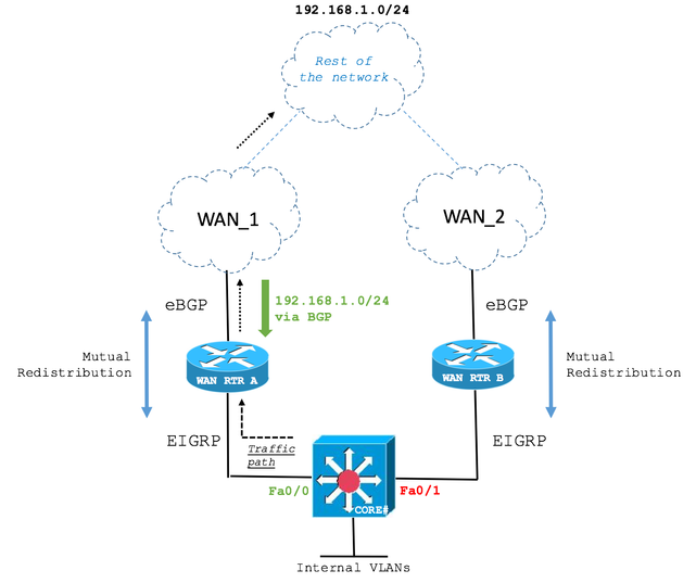
Step 1. Original network state.

The CORE Layer 3 Switch receives the 192.168.1.0/24 route via EIGRP from WAN RTR A and WAN RTR B. The path over WAN RTR A is elected.
The next output shows how the CORE Switch maintains an EIGRP adjacency with both WAN Routers and that WAN RTR A is elected to reach the 192.168.1.0/24 network.
| CORE |
CORE#show ip eigrp neighbors
EIGRP-IPv4 Neighbors for AS(1)
H   Address                 Interface              Hold Uptime   SRTT   RTO  Q  Seq
                                                   (sec)         (ms)       Cnt Num
0   10.1.2.2  (WAN_RTR_A)   Fa0/0                    10 00:05:15   79  1066  0  10
1   10.1.3.3  (WAN_RTR_B)   Fa0/1                    12 00:06:22   76   456  0  5


CORE#show ip route
<snip>
D EX  192.168.1.0/24 [170/28416] via 10.1.2.2, 00:00:32, FastEthernet0/0


CORE#show ip eigrp topology
EIGRP-IPv4 Topology Table for AS(1)/ID(10.10.10.10)
<snip>
P 192.168.1.0/24, 1 successors, FD is 28416, tag is 4
        via 10.1.2.2 (28416/2816), FastEthernet0/0
        via 10.1.3.3 (281856/2816), FastEthernet0/1
|
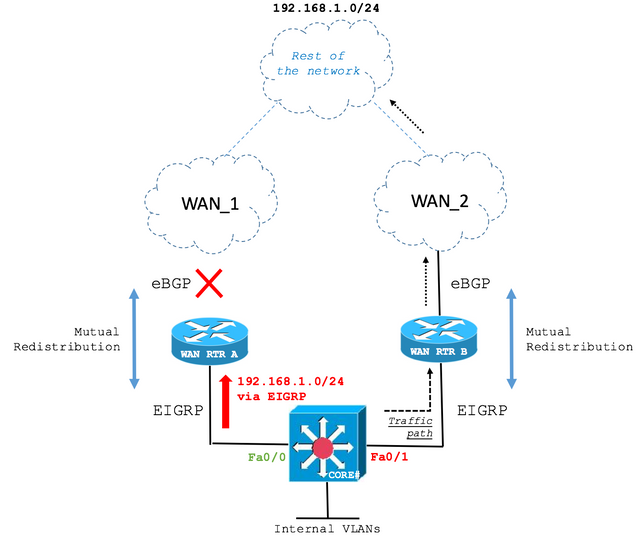
Step 2. Primary WAN link failure.

In case of a link failure, the CORE Switch now installs the route via the second best EIGRP path which is WAN RTR B.
| CORE |
CORE#show ip route
<snip>
D EX  192.168.1.0/24 [170/281856] via 10.1.3.3, 00:00:05, FastEthernet0/1


CORE#show ip eigrp topology
EIGRP-IPv4 Topology Table for AS(1)/ID(10.10.10.10)
<snip>
P 192.168.1.0/24, 1 successors, FD is 28416, tag is 4
        via 10.1.3.3 (281856/2816), FastEthernet0/1
|
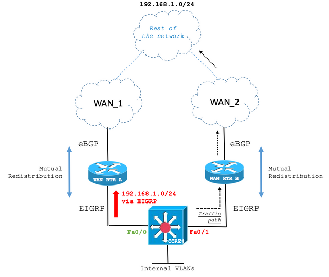
Step 3. Restoration of the primary WAN link.

The primary WAN link has been restored. However, the CORE Switch still routes over the backup path as seen on the next output:
| CORE |
CORE#show ip route
<snip>
D EX  192.168.1.0/24 [170/281856] via 10.1.3.3, 00:06:09, FastEthernet0/1


CORE#show ip eigrp topology
EIGRP-IPv4 Topology Table for AS(1)/ID(10.10.10.10)
<snip>
P 192.168.1.0/24, 1 successors, FD is 28416, tag is 4
        via 10.1.3.3 (281856/2816), FastEthernet0/1
|
The reason for this behavior lies on the BGP Weight path attribute as has been discussed.
In the current state, WAN RTR A shows the route in the Roting Table via EIGRP and in the BGP table redistributed from EIGRP because of the highest value of Weight path attribute wins over the Weight value of the route received via BGP from the re-established WAN link.
| WAN_RTR_A |
WAN_RTR_A#show ip bgp
<snip>
    Network          Next Hop            Metric LocPrf Weight Path
*   192.168.1.0      10.2.4.4                 0             0 4 i
*>                   10.1.2.1            284416         32768 ?


WAN_RTR_A#show ip bgp summary
BGP router identifier 10.20.20.20, local AS number 2
<snip>
Neighbor        V           AS MsgRcvd MsgSent   TblVer  InQ OutQ Up/Down  State/PfxRcd
10.2.4.4        4            4      12      12       16    0    0 00:03:54   (UP) 4


WAN_RTR_A#show ip route
<snip>
D EX  192.168.1.0/24 [170/284416] via 10.1.2.1, 00:08:22, FastEthernet0/0
|
The behavior covered in this document has been widely seen in the field. Network topologies and initial symptoms can differ from the example covered. However, the root cause can be and is often as described in this document. It is important to verify if the configurations and scenario meet the variables for this condition to arise in your network deployment.


 Feedback