Understand Virtual Port Channel (vPC) Enhancements
Available Languages
Download Options
Bias-Free Language
The documentation set for this product strives to use bias-free language. For the purposes of this documentation set, bias-free is defined as language that does not imply discrimination based on age, disability, gender, racial identity, ethnic identity, sexual orientation, socioeconomic status, and intersectionality. Exceptions may be present in the documentation due to language that is hardcoded in the user interfaces of the product software, language used based on RFP documentation, or language that is used by a referenced third-party product. Learn more about how Cisco is using Inclusive Language.
Contents
Introduction
This document describes common Virtual Port Channel (vPC) enhancements configured on Cisco Nexus switches in a vPC domain.
Prerequisites
Requirements
Cisco recommends that you understand basic information surrounding the use case, configuration, and implementation of Virtual Port Channel (vPC). For more information about this feature, refer to one of these applicable documents:
- Cisco Nexus 9000 Series NX-OS Interfaces Configuration Guide, Release 10.5(x)
- Cisco Nexus 9000 Series NX-OS Interfaces Configuration Guide, Release 10.4(x)
- Cisco Nexus 9000 Series NX-OS Interfaces Configuration Guide, Release 10.3(x)
- Cisco Nexus 9000 Series NX-OS Interfaces Configuration Guide, Release 10.2(x)
- Cisco Nexus 9000 Series NX-OS Interfaces Configuration Guide, Release 10.1(x)
- Cisco Nexus 9000 Series NX-OS Interfaces Configuration Guide, Release 9.3(x)
- Cisco Nexus 9000 Series NX-OS Interfaces Configuration Guide, Release 9.2(x)
- Cisco Nexus 9000 Series NX-OS Interfaces Configuration Guide, Release 7.x
- Cisco Nexus 7000 Series NX-OS Interfaces Configuration Guide 8.x
- Cisco Nexus 7000 Series NX-OS Interfaces Configuration Guide 7.x
- Design and Configuration Guide: Best Practices for Virtual Port Channels (vPC) on Cisco Nexus 7000 Series Switches
Components Used
The information in this document was created from the devices in a specific lab environment. All of the devices used in this document started with a cleared (default) configuration. If your network is live, ensure that you understand the potential impact of any command.
Background Information
Since the inception of Cisco NX-OS on Cisco Nexus data center switches, the Virtual Port Channel (vPC) feature has received numerous enhancements that improve the reliability of vPC-connected devices during failure scenarios and optimize forwarding behavior of both vPC peer switches. Understanding the purpose of each enhancement, the change in behavior that the enhancement introduces, and the failure scenarios that the enhancement solves can help you understand why and when an enhancement can be configured within a vPC domain to help best satisfy business needs and requirements.
Applicable Hardware
The procedure covered in this document is applicable to all vPC-capable Cisco Nexus data center switches.
vPC Peer Switch
This section describes the vPC Peer Switch enhancement, which is enabled with the peer-switch vPC domain configuration command.
Overview
In many environments, a pair of Nexus switches in a vPC domain are aggregation or core switches acting as the boundary between Layer 2 switched Ethernet domains and Layer 3 routed domains. Both switches are configured with multiple VLANs and are responsible for routing inter-VLAN east-west traffic as well as north-south traffic. In these environments, the Nexus switches also typically act as root bridges from a Spanning Tree Protocol perspective.
Normally, one vPC peer is configured as the root bridge of the Spanning Tree by setting its Spanning Tree priority to a low value, such as 0. The other vPC peer is configured with a slightly higher Spanning Tree priority, such as 4096, which allows it to take over the role of root bridge within the Spanning Tree if the vPC peer acting as the root bridge fails. With this configuration, the vPC peer acting as the root bridge originates Spanning Tree Bridge Protocol Data Units (BPDUs) with a Bridge ID containing its system MAC address.
However, if the vPC peer acting as the root bridge fails and causes the other vPC peer to take over as the Spanning Tree root bridge, the other vPC peer originates Spanning Tree BPDUs with a Bridge ID containing its system MAC address, which is different from the original root bridge system MAC address. Depending on how downstream bridges are connected, the impact of this change varies and is described in these subsections.
Redundantly-Connected Non-vPC Bridges
Non-vPC-connected bridges that are connected to both vPC peer with redundant links (such that one link is in a Blocking state from a Spanning Tree Protocol perspective) that detect the change in the BPDU (and, therefore, the change in root bridge) observe a change in Root Port. Other Designated Forwarding interfaces immediately transition to a Blocking state, then traverse the Spanning Tree Protocol finite state machine (Blocking, Learning, and Forwarding) with pauses in between equivalent to the configured Spanning Tree Protocol Forward Delay timer (15 seconds by default).
The change in Root Port and subsequent traversal of the Spanning Tree Protocol finite state machine can cause a significant amount of disruption within the network. The vPC Peer Switch enhancement was introduced primarily to prevent network disruption caused by this issue if one of the vPC peers were to go offline. With the vPC Peer Switch enhancement, the non-vPC-connected bridge still has a single redundant link that is in a Blocking state, but immediately transitions that interface to a Forwarding state if the existing Root Port goes down due to link failure. The same process happens when the offline vPC peer comes back online - the interface with the lowest cost to the root bridge seizes the Root Port role, and the redundant link immediately transitions to a Blocking state. The only data plane impact that is observed is the unavoidable loss of packets in-flight that were traversing the vPC peer as it went offline.
vPC-Connected Bridges
vPC-connected bridges in the Spanning Tree domain detect the change in the BPDU (and, therefore, the change in root bridge) and flush dynamically-learned MAC addresses from their local MAC address tables. This behavior is inefficient and unnecessary in topologies with vPC-connected devices that are not reliant on Spanning Tree Protocol for a loop-free topology. vPCs are viewed as a single logical interface from a Spanning Tree Protocol perspective just like normal port-channels, so the loss of a vPC peer is similar to the loss of a single link within a port-channel member. In either scenario, the spanning tree does not change, so the flush of dynamically-learned MAC addresses from bridges in the spanning tree domain (the purpose of which is to allow Ethernet flood-and-learn behavior to re-learn MAC addresses on newly-forwarding interfaces of the spanning tree) is unnecessary.
Furthermore, the flush of dynamically-learned MAC addresses can potentially be disruptive. Consider a scenario where two hosts have a largely unidirectional UDP-based flow (such as a TFTP client sending data to a TFTP server). In this flow, data mostly flows from the TFTP client to the TFTP server - rarely does the TFTP server send a packet back towards the TFTP client. As a result, after a flush of dynamically-learned MAC addresses in the Spanning Tree domain, the TFTP server MAC is not learned for some time. This means the TFTP client data sent towards the TFTP server is flooded throughout the VLAN, as the traffic is unknown-unicast traffic. This can cause large data flows to travel to unintended places within the network and can cause performance issues if it flows through oversubscribed sections of the network.
The vPC Peer Switch enhancement was introduced to prevent this inefficient and unnecessary behavior from occurring in the event that the vPC peer acting as the Spanning Tree root bridge for one or more VLANs is reloaded or powered off.
To enable the vPC Peer Switch enhancement, both vPC peers must have identical Spanning Tree Protocol configuration (including Spanning Tree priority values for all vPC VLANs) and be the Root Bridge for all vPC VLAN. Once these prerequisites are met, the peer-switch vPC domain configuration command must be configured to enable the vPC Peer Switch enhancement.
Note: The vPC Peer Switch enhancement is only supported on a vPC domain which contains the root for all VLANs.
Once the vPC Peer Switch enhancement is enabled, both vPC peers begin originating identical Spanning Tree BPDUs with a Bridge ID containing the vPC system MAC address that is shared by both vPC peers. If a vPC peer is reloaded, the Spanning Tree BPDU that is originated by the remaining vPC peer does not change, so other bridges in the Spanning Tree domain do not see any change in the root bridge and do not react sub-optimally to the change in the network.
Caveats
The vPC Peer Switch enhancement has some caveats you must be aware of prior to configuring it in a production environment.
Spanning Tree Priority Values Must Match Between vPC Peers
Before enabling the vPC Peer Switch enhancement, Spanning Tree priority configuration for all vPC VLANs must be modified so that it is identical between both vPC peers.
Consider the configuration here, where N9K-1 is configured to be the Spanning Tree root bridge for VLANs 1, 10, and 20 with a priority of 0. N9K-2 is the secondary Spanning Tree root bridge for VLANs 1, 10, and 20 with a priority of 4096.
N9K-1# show running-config spanning-tree
spanning-tree vlan 1,10,20 priority 0
interface port-channel1
  spanning-tree port type network

N9K-2# show running-config spanning-tree
spanning-tree vlan 1,10,20 priority 4096
interface port-channel1
  spanning-tree port type network
Prior to enabling the vPC Peer Switch enhancement, you must modify the Spanning Tree priority configuration for VLANs 1, 10, and 20 on N9K-2 to match the Spanning Tree priority configuration for the same VLANs on N9K-1. An example of this modification is shown here.
N9K-2# configure terminal
Enter configuration commands, one per line. End with CNTL/Z.
N9K-2(config)# spanning-tree vlan 1,10,20 priority 0
N9K-2(config)# end
N9K-2# show running-config spanning-tree
spanning-tree vlan 1,10,20 priority 0
interface port-channel1
  spanning-tree port type network

N9K-1# show running-config spanning-tree
spanning-tree vlan 1,10,20 priority 0
interface port-channel1
  spanning-tree port type network
vPC Peer Switch Affect On Non-vPC VLANs
Consider the topology here:
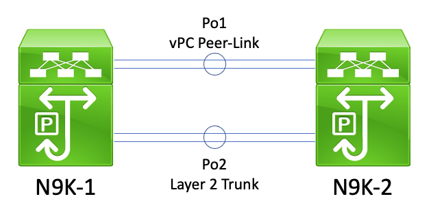
In this topology, two vPC peers (N9K-1 and N9K-2) have two Layer 2 trunks between them - Po1, and Po2. Po1 is the vPC Peer-Link carrying vPC VLANs, while Po2 is a Layer 2 trunk carrying all non-vPC VLANs. If the Spanning Tree priority values for non-vPC VLANs carried across Po2 are identical on N9K-1 and N9K-2, then each vPC peer originates Spanning Tree BPDU frames sourced from the vPC system MAC address, which is identical on both switches. As a result, N9K-1 appears to receive its own Spanning Tree BPDU on Po2 for each non-vPC VLAN, even though N9K-2 is the switch that originated the Spanning Tree BPDU. From a Spanning Tree perspective, N9K-1 places Po2 in a Blocking state for all non-vPC VLANs.
This is expected behavior. To prevent this behavior from occurring or to work around this issue, both vPC peers must be configured with different Spanning Tree priority values on all non-vPC VLANs. This allows one vPC peer to become the root bridge for the non-vPC VLAN and transition the Layer 2 trunk between vPC peers to a Designated Forwarding state. Similarly, the remote vPC peer transitions the Layer 2 trunk between vPC peers to a Designated Root state. This allows traffic in non-vPC VLANs to flow across both vPC peers through the Layer 2 trunk.
Configuration
An example of how to configure the vPC Peer Switch feature can be found here.
In this example, N9K-1 is configured to be the Spanning Tree root bridge for VLANs 1, 10, and 20 with a priority of 0. N9K-2 is the secondary Spanning Tree root bridge for VLANs 1, 10, and 20 with a priority of 4096.
N9K-1# show running-config vpc
<snip>
vpc domain 1
  role priority 150
  peer-keepalive destination 10.122.190.196

interface port-channel1
  vpc peer-link

N9K-2# show running-config vpc
<snip>
vpc domain 1
  peer-keepalive destination 10.122.190.195

interface port-channel1
  vpc peer-link

N9K-1# show running-config spanning-tree
spanning-tree vlan 1,10,20 priority 0
interface port-channel1
  spanning-tree port type network

N9K-2# show running-config spanning-tree
spanning-tree vlan 1,10,20 priority 4096
interface port-channel1
  spanning-tree port type network
First, N9K-2's Spanning Tree priority configuration must be changed to be identical to N9K-1's. This is a requirement in order for the vPC Peer Switch feature to function as expected. If N9K-2's system MAC address is lower than N9K-1's system MAC address, then N9K-2 usurps the role of root bridge for the Spanning Tree domain, which causes other bridges in the Spanning Tree domain to flush their local MAC address tables for all affected VLANs. An example of this phenomenon is shown here.
N9K-1# show spanning-tree vlan 1

VLAN0001
  Spanning tree enabled protocol rstp
  Root ID    Priority    1
             Address     689e.0baa.dea7
             This bridge is the root
             Hello Time  2  sec  Max Age 20 sec  Forward Delay 15 sec

  Bridge ID  Priority    1      (priority 0 sys-id-ext 1)
             Address     689e.0baa.dea7
             Hello Time  2  sec  Max Age 20 sec  Forward Delay 15 sec

Interface        Role Sts Cost      Prio.Nbr Type
---------------- ---- --- --------- -------- --------------------------------
Po1              Desg FWD 1         128.4096 (vPC peer-link) Network P2p
Po10             Desg FWD 1         128.4105 (vPC) P2p
Po20             Desg FWD 1         128.4115 (vPC) P2p

N9K-2# show spanning-tree vlan 1

VLAN0001
  Spanning tree enabled protocol rstp
  Root ID    Priority    1
             Address     689e.0baa.dea7
             Cost        1
             Port        4096 (port-channel1)
             Hello Time  2  sec  Max Age 20 sec  Forward Delay 15 sec

  Bridge ID  Priority    4097   (priority 4096 sys-id-ext 1)
             Address     689e.0baa.de07
             Hello Time  2  sec  Max Age 20 sec  Forward Delay 15 sec

Interface        Role Sts Cost      Prio.Nbr Type
---------------- ---- --- --------- -------- --------------------------------
Po1              Root FWD 1         128.4096 (vPC peer-link) Network P2p
Po10             Desg FWD 1         128.4105 (vPC) P2p
Po20             Desg FWD 1         128.4115 (vPC) P2p

N9K-2# configure terminal
Enter configuration commands, one per line. End with CNTL/Z.
N9K-2(config)# spanning-tree vlan 1,10,20 priority 0
N9K-2(config)# end
N9K-2# show spanning-tree vlan 1

VLAN0001
  Spanning tree enabled protocol rstp
  Root ID    Priority    1
             Address     689e.0baa.de07
             This bridge is the root
             Hello Time  2  sec  Max Age 20 sec  Forward Delay 15 sec

  Bridge ID  Priority    1      (priority 0 sys-id-ext 1)
             Address     689e.0baa.de07
             Hello Time  2  sec  Max Age 20 sec  Forward Delay 15 sec

Interface        Role Sts Cost      Prio.Nbr Type
---------------- ---- --- --------- -------- --------------------------------
Po1              Desg FWD 1         128.4096 (vPC peer-link) Network P2p
Po10             Desg FWD 1         128.4105 (vPC) P2p
Po20             Desg FWD 1         128.4115 (vPC) P2p
Next, we can enable the vPC Peer Switch feature through the peer-switch vPC domain configuration command. This changes the Bridge ID within Spanning Tree BPDUs originated by both vPC peers, which causes other bridges in the Spanning Tree domain to flush their local MAC address tables for all affected VLANs.
N9K-1# configure terminal
N9K-1(config)# vpc domain 1
N9K-1(config-vpc-domain)# peer-switch
N9K-1(config-vpc-domain)# end
N9K-1#

N9K-2# configure terminal
N9K-2(config)# vpc domain 1
N9K-2(config-vpc-domain)# peer-switch
N9K-2(config-vpc-domain)# end
N9K-2#
You can verify that the vPC Peer Switch feature is operating as expected by validating both vPC peers claim to be the root bridge for vPC VLANs with the show spanning-tree summary command. This output must also state that the vPC Peer Switch feature is enabled and operational.
N9K-1# show spanning-tree summary
Switch is in rapid-pvst mode
Root bridge for: VLAN0001, VLAN0010, VLAN0020
L2 Gateway STP                           is disabled
Port Type Default                        is disable
Edge Port [PortFast] BPDU Guard Default  is disabled
Edge Port [PortFast] BPDU Filter Default is disabled
Bridge Assurance                         is enabled
Loopguard Default                        is disabled
Pathcost method used                     is short
vPC peer-switch                          is enabled (operational)
STP-Lite                                 is disabled

Name                   Blocking Listening Learning Forwarding STP Active
---------------------- -------- --------- -------- ---------- ----------
VLAN0001                     0         0        0          3          3
VLAN0010                     0         0        0          3          3
VLAN0020                     0         0        0          3          3
---------------------- -------- --------- -------- ---------- ----------
3 vlans                      0         0        0          9          9

N9K-2# show spanning-tree summary
Switch is in rapid-pvst mode
Root bridge for: VLAN0001, VLAN0010, VLAN0020
L2 Gateway STP                           is disabled
Port Type Default                        is disable
Edge Port [PortFast] BPDU Guard Default  is disabled
Edge Port [PortFast] BPDU Filter Default is disabled
Bridge Assurance                         is enabled
Loopguard Default                        is disabled
Pathcost method used                     is short
vPC peer-switch                          is enabled (operational)
STP-Lite                                 is disabled

Name                   Blocking Listening Learning Forwarding STP Active
---------------------- -------- --------- -------- ---------- ----------
VLAN0001                     0         0        0          3          3
VLAN0010                     0         0        0          3          3
VLAN0020                     0         0        0          3          3
---------------------- -------- --------- -------- ---------- ----------
3 vlans                      0         0        0          9          9
Use the show spanning-tree vlan {x} command to view more detailed information about a specific VLAN. The switch holding the Primary or Operational Primary vPC role has all of its interfaces in a Designated Forwarding state. The switch holding the Secondary or Operational Secondary vPC role has all of its interfaces in a Designated Forwarding state except for the vPC Peer-Link, which is in a Root Forwarding state. Note that the vPC system MAC address displayed in the output of show vpc role is identical to the Root Bridge ID and Bridge ID of each vPC peer.
N9K-1# show vpc role

vPC Role status
----------------------------------------------------
vPC role                        : primary
Dual Active Detection Status    : 0
vPC system-mac                  : 00:23:04:ee:be:01
vPC system-priority             : 32667
vPC local system-mac            : 68:9e:0b:aa:de:a7
vPC local role-priority         : 150
vPC local config role-priority  : 150
vPC peer system-mac             : 68:9e:0b:aa:de:07
vPC peer role-priority          : 32667
vPC peer config role-priority   : 32667

N9K-1# show spanning-tree vlan 1

VLAN0001
  Spanning tree enabled protocol rstp
  Root ID    Priority    1
             Address     0023.04ee.be01
             This bridge is the root
             Hello Time  2  sec  Max Age 20 sec  Forward Delay 15 sec

  Bridge ID  Priority    1      (priority 0 sys-id-ext 1)
             Address     0023.04ee.be01
             Hello Time  2  sec  Max Age 20 sec  Forward Delay 15 sec

Interface        Role Sts Cost      Prio.Nbr Type
---------------- ---- --- --------- -------- --------------------------------
Po1              Desg FWD 1         128.4096 (vPC peer-link) Network P2p
Po10             Desg FWD 1         128.4105 (vPC) P2p
Po20             Desg FWD 1         128.4115 (vPC) P2p

N9K-2# show vpc role

vPC Role status
----------------------------------------------------
vPC role                        : secondary
Dual Active Detection Status    : 0
vPC system-mac                  : 00:23:04:ee:be:01
vPC system-priority             : 32667
vPC local system-mac            : 68:9e:0b:aa:de:07
vPC local role-priority         : 32667
vPC local config role-priority  : 32667
vPC peer system-mac             : 68:9e:0b:aa:de:a7
vPC peer role-priority          : 150
vPC peer config role-priority   : 150

N9K-2# show spanning-tree vlan 1

VLAN0001
  Spanning tree enabled protocol rstp
  Root ID    Priority    1
             Address     0023.04ee.be01
             This bridge is the root
             Hello Time  2  sec  Max Age 20 sec  Forward Delay 15 sec

  Bridge ID  Priority    1      (priority 0 sys-id-ext 1)
             Address     0023.04ee.be01
             Hello Time  2  sec  Max Age 20 sec  Forward Delay 15 sec

Interface        Role Sts Cost      Prio.Nbr Type
---------------- ---- --- --------- -------- --------------------------------
Po1              Root FWD 1         128.4096 (vPC peer-link) Network P2p
Po10             Desg FWD 1         128.4105 (vPC) P2p
Po20             Desg FWD 1         128.4115 (vPC) P2p
Finally, we can use the Ethanalyzer control plane packet capture utility on either vPC peer to confirm that both vPC peers are originating Spanning Tree BPDUs with a Bridge ID and Root Bridge ID containing the vPC system MAC address shared between both vPC peers.
N9K-1# ethanalyzer local interface inband display-filter stp limit-captured-frames 0
<snip>
Capturing on inband
2021-05-13 01:59:51.664206 68:9e:0b:aa:de:d4 -> 01:80:c2:00:00:00 STP RST. Root = 0/1/00:23:04:ee:be:01  Cost = 0  Port = 0x9000

N9K-2# ethanalyzer local interface inband display-filter stp limit-captured-frames 0
<snip>
Capturing on inband
2021-05-13 01:59:51.777034 68:9e:0b:aa:de:34 -> 01:80:c2:00:00:00 STP RST. Root = 0/1/00:23:04:ee:be:01  Cost = 0  Port = 0x9000
Impact
The impact of enabling the vPC Peer Switch enhancement varies depending on whether other bridges in the Spanning Tree domain are connected to both vPC peers via a vPC, or if they are redundantly connected to both vPC peers without a vPC.
Redundantly-Connected Non-vPC Bridges
If a non-vPC-connected bridge with redundant links to both vPC peers (such that one link is in a Blocking state from a Spanning Tree Protocol perspective) detects a change in the Spanning Tree root bridge advertised in Spanning Tree BPDUs, the Root Port of the bridge can change between the two redundant interfaces. In turn, this can cause other Designated Forwarding interfaces to immediately transition to a Blocking state, then traverse the Spanning Tree Protocol finite state machine (Blocking, Learning, and Forwarding) with pauses in between equivalent to the configured Spanning Tree Protocol Forward Delay timer (15 seconds by default). The change in Root Port and subsequent traversal of the Spanning Tree Protocol finite state machine can cause a significant amount of disruption within the network.
It is worth mentioning that this impact occurs whenever the vPC peer that is presently the root bridge for the Spanning Tree domain goes offline (such as in the event of power failure, hardware failure, or a reload). This behavior is not specific to the vPC Peer Switch enhancement - enabling the vPC Peer Switch enhancement simply causes similar behavior as a vPC peer going offline from a Spanning Tree perspective.
vPC-Connected Bridges
If a vPC-connected bridge detects a change in the Spanning Tree root bridge advertised in Spanning Tree BPDUs, the bridge flushes dynamically-learned MAC addresses from its MAC address table. While configuring the vPC Peer Switch feature, you can observe this behavior under these two scenarios:
- When Spanning Tree priority values are configured to match between both vPC peers, the Spanning Tree root bridge can change from one vPC peer to another if the vPC peer that was previously not the root bridge has a lower system MAC address than the vPC peer that was previously the root bridge. An example of this scenario is shown in the vPC Peer Switch Configuration section of this document.
- When the vPC Peer Switch feature is enabled through the peer-switch vPC domain configuration command, both vPC peers begin operating as root bridges of the Spanning Tree domain. Both vPC peers begin originating identical Spanning Tree BPDUs asserting themselves as the root bridge of the Spanning Tree domain.
In most scenarios and topologies, no data plane impact is observed as a result of either of these two scenarios. However, for a short period of time, data plane traffic is flooded within a VLAN due to unknown unicast flooding, as the destination MAC address of frames are not learned on any switchport as a direct result of the flush of dynamically-learned MAC addresses. In some topologies, this can cause brief periods of performance issues or packet loss if data plane traffic is flooded to oversubscribed network devices within the VLAN. This can also cause issues with bandwidth-intensive unidirectional traffic flows or silent hosts (hosts that primarily receive packets and rarely send packets), as this traffic is flooded within the VLAN for an extended period of time instead of being switched directly to the destination host as normal.
It is worth mentioning that this impact is related to the flush of dynamically-learned MAC addresses from the MAC address table of bridges within the affected VLAN. This behavior is not specific to the vPC Peer Switch enhancement or a change in root bridge - it can also be caused by a Topology Change Notification generated due to a non-edge port coming up within the VLAN.
Example Failure Scenarios
Redundantly-Connected Non-vPC Bridges Restarting Finite State Machine
Consider the topology here:
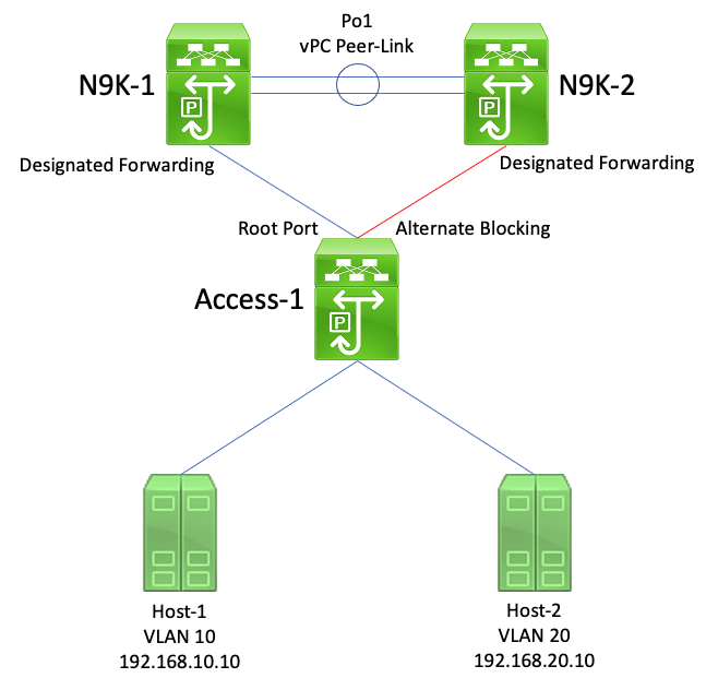
In this topology, N9K-1 and N9K-2 are vPC peers in a vPC domain. N9K-1 is configured with a Spanning Tree priority value of 0 for all VLANs, making N9K-1 the root bridge for all VLANs. N9K-2 is configured with a Spanning Tree priority value of 4096 for all VLANs, making N9K-2 the secondary root bridge for all VLANs. Access-1 is a switch that is redundantly connected to both N9K-1 and N9K-2 through Layer 2 switchports. These switchports are not bundled into a port-channel, so Spanning Tree Protocol places the link connected to N9K-1 in a Designated Root state and the link connected to N9K-2 in an Alternate Blocking state.
Consider a failure scenario where N9K-1 goes offline due to a hardware failure, power failure, or a reload of the switch. N9K-2 asserts itself as the root bridge for all VLANs by advertising Spanning Tree BPDUs using its system MAC address as the bridge ID. Access-1 sees a change in the root bridge ID. Furthermore, its Designated Root port transitions to a down/down state, which means the new Designated Root port is the link that was in an Alternate Blocking state facing N9K-2.
This change in Designated Root ports causes all non-edge Spanning Tree ports to step through the Spanning Tree Protocol finite state machine (Blocking, Learning, and Forwarding) with pauses in between equivalent to the configured Spanning Tree Protocol Forward Delay timer (15 seconds by default). This process can be extremely disruptive to the network.
In the same failure scenario with the vPC Peer Switch enhancement enabled, both N9K-1 and N9K-2 transmit identical Spanning Tree BPDUs using the shared vPC system MAC address as the bridge ID. If N9k-1 fails, N9K-2 continues transmitting this same Spanning Tree BPDU. As a result, Access-1 immediately transitions the Alternate Blocking link towards N9K-2 to a Designated Root state and begin forwarding traffic across the link. Furthermore, the fact that the Spanning Tree root bridge ID does not change prevents non-edge ports from stepping through the Spanning Tree Protocol finite state machine, which reduces the amount of disruption observed in the network.
vPC-Connected Bridges Flushing Dynamically-Learned MAC Addresses
Consider the topology here:
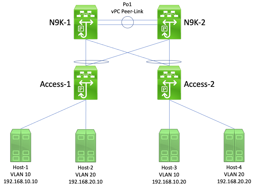
In this topology, N9K-1 and N9K-2 are vPC peers in a vPC domain that perform inter-VLAN routing between VLAN 10 and VLAN 20. N9K-1 is configured with a Spanning Tree priority value of 0 for VLAN 10 and VLAN 20, making N9K-1 the root bridge for both VLANs. N9K-2 is configured with a Spanning Tree priority value of 4096 for VLAN 10 and VLAN 20, making N9K-2 the secondary root bridge for both VLANs. Host-1, Host-2, Host-3, and Host-4 are all continuously communicating with each other.
Consider a failure scenario where N9K-1 goes offline due to a hardware failure, power failure, or a reload of the switch. N9K-2 asserts itself as the root bridge for VLAN 10 and VLAN 20 by advertising Spanning Tree BPDUs using its system MAC address as the bridge ID. Access-1 and Access-2 see a change in the root bridge ID, and although the spanning tree remains the same (meaning, the vPC facing N9K-1 and N9K-2 remains a Designated Root port) both Access-1 and Access-2 flush their MAC address of all dynamically-learned MAC addresses in VLAN 10 and VLAN 20.
In most environments, the flushing of dynamically-learned MAC addresses causes a minimal amount of impact. No packets are lost (aside from those lost as they were transmitted to N9K-1 while it failed), but traffic is temporarily flooded within each broadcast domain as unknown unicast traffic while all switches in the broadcast domain re-learn dynamic MAC addresses.
In the same failure scenario with the vPC Peer Switch enhancement enabled, both N9K-1 and N9K-2 would be transmitting identical Spanning Tree BPDUs using the shared vPC system MAC address as the bridge ID. If N9k-1 fails, N9K-2 continues transmitting this same Spanning Tree BPDU. As a result, Access-1 and Access-2 are unaware that any change in the Spanning Tree topology has taken place - from their perspective, the root bridge Spanning Tree BPDUs are identical, so there is no need to flush dynamically-learned MAC addresses from relevant VLANs. This prevents the flooding of unknown unicast traffic in each broadcast domain in this failure scenario.
vPC Peer Gateway
This section describes the vPC Peer Gateway enhancement, which is enabled with the peer-gateway vPC domain configuration command.
Overview
Nexus switches configured in a vPC domain perform dual-active First Hop Redundancy Protocol (FHRP) forwarding by default. This means that if either vPC peer receives a packet with a destination MAC address belonging to a Hot Standby Router Protocol (HSRP) or Virtual Router Redundancy Protocol (VRRP) group configured on the switch, the switch routes the packet according to its local routing table regardless of its HSRP or VRRP control plane state. In other words, it is expected behavior for a vPC peer in an HSRP Standby or VRRP Backup state to route packets destined to the HSRP or VRRP virtual MAC address.
When a vPC peer routes a packet destined to an FHRP virtual MAC address, it rewrites the packet with a new source and destination MAC address. The source MAC address is the MAC address of the vPC peer Switched Virtual Interface (SVI) within the VLAN that the packet is routed into. The destination MAC address is the MAC address associated with the next-hop IP address for the destination IP address of the packet according to the vPC peer local routing table. In inter-VLAN routing scenarios, the destination MAC address of the packet after the packet has been rewritten is the MAC address of the host that the packet is ultimately destined to.
Some hosts do not follow standard forwarding behavior as an optimization feature. With this behavior, the host does not perform a routing table and/or ARP cache lookup when replying to an incoming packet. Instead, the host flips the source and destination MAC addresses of the incoming packet for the reply packet. In other words, the source MAC address of the incoming packet becomes the destination MAC address of the reply packet, and the destination MAC address of the incoming packet becomes the source MAC address of the reply packet. This behavior differs from a host that follows standard forwarding behavior, which would perform a local routing table and/or ARP cache lookup and set the destination MAC address of the reply packet to the FHRP virtual MAC address.
This non-standard host behavior can violate the vPC Loop Avoidance rule if the reply packet generated by the host is addressed to one vPC peer, but egresses the vPC towards the other vPC peer. The other vPC peer receives the packet destined to a MAC address owned by its vPC peer and forwards the packet out of the vPC Peer-Link towards the vPC peer that owns the MAC address present in the destination MAC address field of the packet. The vPC peer that owns the MAC address attempts to route the packet locally. If the packet needs to egress a vPC, then the vPC peer drops this packet for violating the vPC Loop Avoidance rule. As a result, you can observe connectivity issues or packet loss for some flows sourced from or destined to a host utilizing this non-standard behavior.
The vPC Peer Gateway enhancement was introduced to eliminate the packet loss introduced by hosts utilizing this non-standard behavior. This is done by allowing one vPC peer to locally route packets destined to the MAC address of the other vPC peer such that packets destined to the remote vPC peer do not need to egress the vPC Peer-Link in order to be routed. In other words, the vPC Peer Gateway enhancement allows one vPC peer to route packets "on behalf of" the remote vPC peer. The vPC Peer Gateway enhancement can be enabled with the peer-gateway vPC domain configuration command.
Caveats
Flapping of Unicast Routing Protocol Adjacencies over vPCs or vPC VLANs
If dynamic unicast routing protocol adjacencies are formed between two vPC peers and a vPC-connected router or a router connected through a vPC orphan port, the routing protocol adjacencies can start flapping continuously after enabling the vPC Peer Gateway enhancement if the Routing/Layer 3 over vPC enhancement is not configured immediately afterwards. These failure scenarios are described in detail in the Unicast Routing Protocol Adjacencies over a vPC with vPC Peer Gateway Example Failure Scenario and Unicast Routing Protocol Adjacencies over a vPC VLAN with vPC Peer Gateway sections of this document.
To resolve this issue, enable the Routing/Layer 3 over vPC enhancement with the layer3 peer-router vPC domain configuration command immediately after enabling the vPC Peer Gateway enhancement with the peer-gateway vPC domain configuration command.
Automatic Disabling of ICMP and ICMPv6 Redirects
When the vPC Peer Gateway enhancement is enabled, the generation of ICMP and ICMPv6 Redirect packets is automatically disabled on all vPC VLAN SVIs (that is, any SVI associated with a VLAN that is trunked across the vPC Peer-Link). The switch does this by configuring no ip redirects and no ipv6 redirects on all vPC VLAN SVIs. This prevents a switch from generating ICMP Redirect packets in response to packets that ingress the switch, but have a destination MAC and IP address of the switch vPC peer.
If ICMP or ICMPv6 Redirect packets are necessary in your environment within a specific VLAN, you need to exclude this VLAN from taking advantage of the vPC Peer Gateway enhancement using the peer-gateway exclude-vlan <vlan-id> vPC domain configuration command.
Note: The peer-gateway exclude-vlan <vlan-id> vPC domain configuration command is not supported on Nexus 9000 Series switches.
Configuration
An example of how to configure the vPC Peer Gateway feature can be found here.
In this example, N9K-1 and N9K-2 are vPC peers in a vPC domain. Both vPC peers have an HSRP group configured for VLAN 10. N9K-1 is the HSRP Active router with a priority of 150, while N9K-2 is the HSRP Standby router with the default priority of 100.
N9K-1# show running-config vpc
<snip>
vpc domain 1
  role priority 150
  peer-keepalive destination 10.82.140.43

interface port-channel1
  vpc peer-link

N9K-2# show running-config vpc
<snip>
vpc domain 1
  peer-keepalive destination 10.82.140.42

interface port-channel1
  vpc peer-link

N9K-1# show running-config interface vlan 10
<snip>
interface Vlan10
  no shutdown
  ip address 192.168.10.2/24
  hsrp 10
    preempt
    priority 150
    ip 192.168.10.1

N9K-2# show running-config interface vlan 10
<snip>
interface Vlan10
  no shutdown
  ip address 192.168.10.3/24
  hsrp 10
    ip 192.168.10.1

N9K-1# show hsrp interface vlan 10 brief
*:IPv6 group   #:group belongs to a bundle
                     P indicates configured to preempt.
                     |
 Interface   Grp  Prio P State    Active addr      Standby addr     Group addr
  Vlan10      10   150  P Active   local            192.168.10.3     192.168.10.1    (conf)

N9K-2# show hsrp interface vlan 10 brief
*:IPv6 group   #:group belongs to a bundle
                     P indicates configured to preempt.
                     |
 Interface   Grp  Prio P State    Active addr      Standby addr     Group addr
  Vlan10      10   100    Standby  192.168.10.2     local            192.168.10.1    (conf)
N9K-1's VLAN 10 SVI has a MAC address of 00ee.ab67.db47, and N9K-2's VLAN 10 SVI has a MAC address of 00ee.abd8.747f. The HSRP virtual MAC address for VLAN 10 is 0000.0c07.ac0a. In this state, the VLAN 10 SVI MAC address of each switch and the HSRP virtual MAC address is present in the MAC address table of each switch. The VLAN 10 SVI MAC address of each switch and the HSRP virtual MAC address has the Gateway (G) flag present, which indicates that the switch locally routes packets destined to this MAC address.
Note that N9K-1's MAC address table does not have the Gateway flag present for N9K-2's VLAN 10 SVI MAC address. Similarly, N9K-2's MAC address table does not have the Gateway flag present for N9K-1's VLAN 10 SVI MAC address.
N9K-1# show mac address-table vlan 10
Legend:
        * - primary entry, G - Gateway MAC, (R) - Routed MAC, O - Overlay MAC
        age - seconds since last seen,+ - primary entry using vPC Peer-Link,
        (T) - True, (F) - False, C - ControlPlane MAC, ~ - vsan
   VLAN     MAC Address      Type      age     Secure NTFY Ports
---------+-----------------+--------+---------+------+----+------------------
G   10     0000.0c07.ac0a   static   -         F      F    sup-eth1(R)
G   10     00ee.ab67.db47   static   -         F      F    sup-eth1(R)
*   10     00ee.abd8.747f   static   -         F      F    vPC Peer-Link(R)

N9K-2# show mac address-table vlan 10
Legend:
        * - primary entry, G - Gateway MAC, (R) - Routed MAC, O - Overlay MAC
        age - seconds since last seen,+ - primary entry using vPC Peer-Link,
        (T) - True, (F) - False, C - ControlPlane MAC, ~ - vsan
   VLAN     MAC Address      Type      age     Secure NTFY Ports
---------+-----------------+--------+---------+------+----+------------------
G   10     0000.0c07.ac0a   static   -         F      F    vPC Peer-Link(R)
*   10     00ee.ab67.db47   static   -         F      F    vPC Peer-Link(R)
G   10     00ee.abd8.747f   static   -         F      F    sup-eth1(R)
We can enable the vPC Peer Gateway enhancement through the peer-gateway vPC domain configuration command. This allows the switch to locally route received packets with a destination MAC address belonging to their vPC peer MAC address learned on the vPC Peer-Link. This is done by setting the Gateway flag on the vPC peer MAC address within the MAC address table of the switch.
N9K-1# configure terminal
Enter configuration commands, one per line. End with CNTL/Z.
N9K-1(config)# vpc domain 1
N9K-1(config-vpc-domain)# peer-gateway
N9K-1(config-vpc-domain)# end
N9K-1#

N9K-2# configure terminal
Enter configuration commands, one per line. End with CNTL/Z.
N9K-2(config)# vpc domain 1
N9K-2(config-vpc-domain)# peer-gateway
N9K-2(config-vpc-domain)# end
N9K-2#
You can verify the vPC Peer Gateway enhancement is operating as expected by validating the Gateway flag is present in the MAC Address Table for the vPC Peer's MAC.
N9K-1# show mac address-table vlan 10
Legend:
        * - primary entry, G - Gateway MAC, (R) - Routed MAC, O - Overlay MAC
        age - seconds since last seen,+ - primary entry using vPC Peer-Link,
        (T) - True, (F) - False, C - ControlPlane MAC, ~ - vsan
   VLAN     MAC Address      Type      age     Secure NTFY Ports
---------+-----------------+--------+---------+------+----+------------------
G   10     0000.0c07.ac0a   static   -         F      F    sup-eth1(R)
G   10     00ee.ab67.db47   static   -         F      F    sup-eth1(R)
G   10     00ee.abd8.747f   static   -         F      F    vPC Peer-Link(R)

N9K-2# show mac address-table vlan 10
Legend:
        * - primary entry, G - Gateway MAC, (R) - Routed MAC, O - Overlay MAC
        age - seconds since last seen,+ - primary entry using vPC Peer-Link,
        (T) - True, (F) - False, C - ControlPlane MAC, ~ - vsan
   VLAN     MAC Address      Type      age     Secure NTFY Ports
---------+-----------------+--------+---------+------+----+------------------
G   10     0000.0c07.ac0a   static   -         F      F    vPC Peer-Link(R)
G   10     00ee.ab67.db47   static   -         F      F    vPC Peer-Link(R)
G   10     00ee.abd8.747f   static   -         F      F    sup-eth1(R)
Impact
The impact of enabling the vPC Peer Gateway enhancement can vary depending on the surrounding topology and the behavior of connected hosts as described in these sub-sections. If neither of these sub-sections apply to your environment, then enabling the vPC Peer Gateway enhancement is not disruptive and does not have impact on your environment.
Flapping of Unicast Routing Protocol Adjacencies over vPCs or vPC VLANs
If dynamic unicast routing protocol adjacencies are formed between two vPC peers and a vPC-connected router or a router connected through a vPC orphan port, the routing protocol adjacencies can start flapping continuously after enabling the vPC Peer Gateway enhancement if the Routing/Layer 3 over vPC enhancement is not configured immediately afterwards. These failure scenarios are described in detail in the Unicast Routing Protocol Adjacencies over a vPC with vPC Peer Gateway Example Failure Scenario and Unicast Routing Protocol Adjacencies over a vPC VLAN with vPC Peer Gateway sections of this document.
To resolve this issue, enable the Routing/Layer 3 over vPC enhancement with the layer3 peer-router vPC domain configuration command immediately after enabling the vPC Peer Gateway enhancement with the peer-gateway vPC domain configuration command.
Automatic Disabling of ICMP and ICMPv6 Redirects
When the vPC Peer Gateway enhancement is enabled, the generation of ICMP and ICMPv6 Redirect packets is automatically disabled on all vPC VLAN SVIs (that is, any SVI associated with a VLAN that is trunked across the vPC Peer-Link). The switch does this by configuring no ip redirects and no ipv6 redirects on all vPC VLAN SVIs. This prevents a switch from generating ICMP Redirect packets in response to packets that ingress the switch, but have a destination MAC and IP address of the switch vPC peer.
If ICMP or ICMPv6 Redirect packets are necessary in your environment within a specific VLAN, you need to exclude this VLAN from taking advantage of the vPC Peer Gateway enhancement using the peer-gateway exclude-vlan <vlan-id> vPC domain configuration command.
Note: The peer-gateway exclude-vlan <vlan-id> vPC domain configuration command is not supported on Nexus 9000 Series switches.
Example Failure Scenarios
vPC-Connected Hosts with Non-Standard Forwarding Behavior
Consider the topology here:
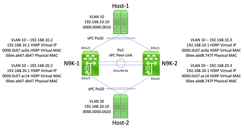
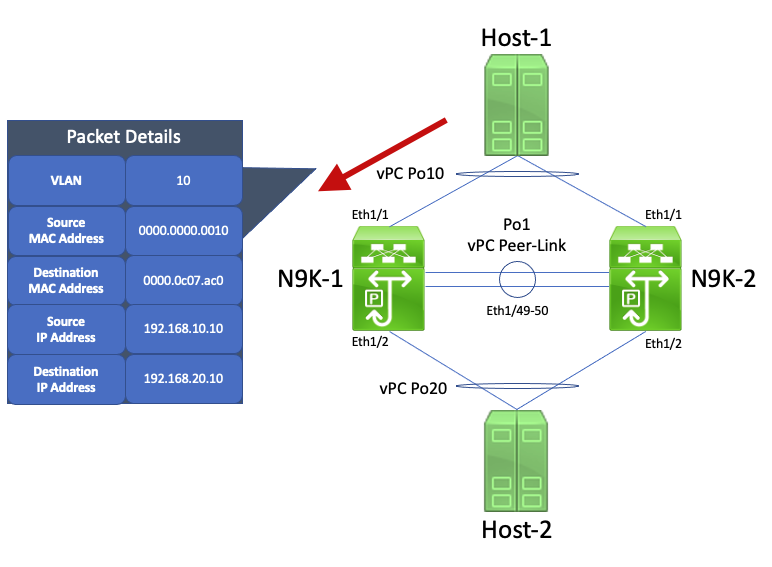
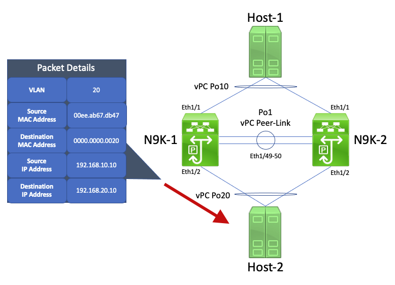
In this topology, N9K-1 and N9K-2 are vPC peers in a vPC domain that perform inter-VLAN routing between VLAN 10 and VLAN 20. Interface Po1 is the vPC Peer-Link. A host named Host-1 is connected via vPC Po10 to N9K-1 and N9K-2 in VLAN 10. Host-1 owns an IP address of 192.168.10.10 with a MAC address of 0000.0000.0010. A host named Host-2 is connected via vPC Po20 to N9K-1 and N9K-2 in VLAN 20. Host-2 owns an IP address of 192.168.20.10 with a MAC address of 0000.0000.0020.
N9K-1 and N9K-2 both have SVIs in VLAN 10 and VLAN 20 with HSRP activated under each SVI. N9K-1's VLAN 10 interface has an IP address of 192.168.10.2, and N9K-1's VLAN 20 interface has an IP address of 192.168.20.2. Both of N9K-1's SVIs have a physical MAC address of 00ee.ab67.db47. N9K-2's VLAN 10 interface has an IP address of 1921.68.10.3, and N9K-2's VLAN 20 interface has an IP address of 192.168.20.3. Both of N9K-2's SVIs have a physical MAC address of 00ee.abd8.747f. The HSRP virtual IP address for VLAN 10 is 192.168.10.1, and the HSRP virtual MAC address is 0000.0c07.ac0a. The HSRP virtual IP address for VLAN 20 is 192.168.20.1, and the HSRP virtual MAC address is 0000.0c07.ac14.
Consider a scenario where Host-1 sends an ICMP Echo Request packet to Host-2. After Host-1 resolves ARP for its default gateway (the HSRP virtual IP address), Host-1 follows standard forwarding behavior and generates an ICMP Echo Request packet with a source IP address of 192.168.10.10, a destination IP address of 192.168.20.10, a source MAC address of 0000.0000.0010, and a destination MAC address of 0000.0c07.ac0a. This packet egresses towards N9K-1. A visual example of this is shown here.
N9K-1 receives this packet. Since this packet is destined to the HSRP virtual MAC address, N9K-1 is able to route this packet according to its local routing table regardless of its HSRP control plane state. This packet is routed from VLAN 10 into VLAN 20. As part of routing the packet, N9K-1 performs packet rewrite by re-addressing the source and destination MAC address fields of the packet. The new source MAC address of the packet is the physical MAC address associated with N9K-1's VLAN 20 SVI (00ee.ab67.db47), and the new destination MAC address is the MAC address associated with Host-2 (0000.0000.0020). A visual example of this is shown here.
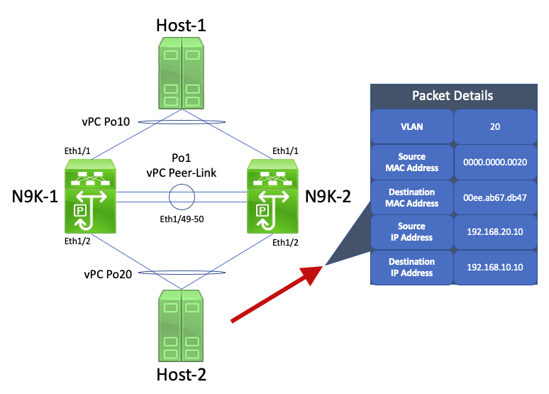
Host-2 receives this packet and generates an ICMP Echo Reply packet in response to Host-1's ICMP Echo Request packet. However, when Host-2 does not follow standard forwarding behavior. To optimize its forwarding, Host-2 does not perform a routing table or ARP cache lookup for Host-1's IP address (192.168.10.10) - instead, it inverts the source MAC address and destination MAC address fields of the ICMP Echo Request packet Host-2 originally received. As a result, the ICMP Echo Reply packet generated by Host-2 has a source IP address of 192.168.20.10, a destination IP address of 192.168.10.10, a source MAC address of 0000.0000.0020, and a destination MAC address of 00ee.ab67.db47.
If this ICMP Echo Reply packet egresses towards N9K-1, this packet is forwarded towards Host-1 without issue. However, consider a scenario where this ICMP Echo Reply packet egresses towards N9K-2, as shown here.
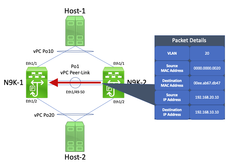
N9K-2 receives this packet. Since this packet is destined to the physical MAC address of N9K-1's VLAN 20 SVI, N9K-2 forwards this packet across the vPC Peer-Link towards N9K-1, as N9K-2 cannot route this packet on behalf of N9K-1. A visual example of this is shown here.
N9K-1 receives this packet. Since this packet is destined to the physical MAC address of N9K-1's VLAN 20 SVI, N9K-1 is able to route this packet according to its local routing table regardless of its HSRP control plane state. This packet is routed from VLAN 20 into VLAN 10. However, the egress interface for this route resolves to vPC Po10, which is up on N9K-2. This is a violation of the vPC Loop Avoidance rule - if N9K-1 receives a packet through the vPC Peer-Link, N9K-1 cannot forward that packet out of a vPC interface if the same vPC interface is up on N9K-2. N9K-1 drops this packet as a result of this violation. A visual example of this is shown here.
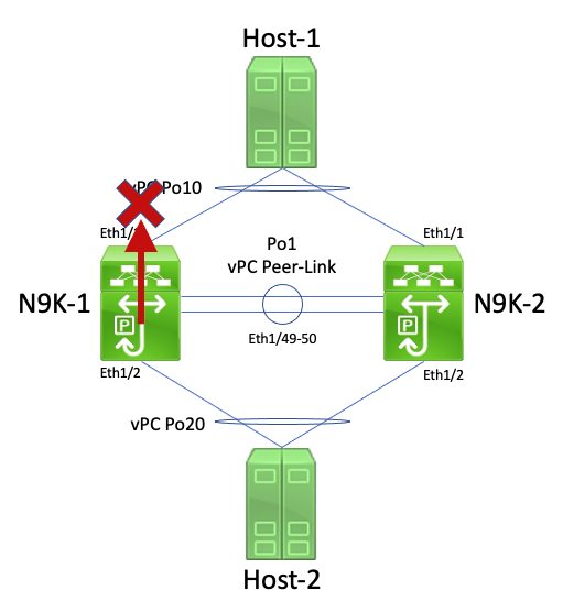
You can resolve this issue by enabling the vPC Peer Gateway enhancement with the peer-gateway vPC domain configuration command. This allows N9K-2 to route the ICMP Echo Reply packet (and other packets addressed similarly) on behalf of N9K-1, even though the destination MAC address of the packet is owned by N9K-1 and not N9K-2. As a result, N9K-2 can forward this packet out of its vPC Po10 interface instead of forwarding it across the vPC Peer-Link.
Routing/Layer 3 over vPC (Layer3 Peer Router)
This section describes the Routing/Layer 3 over vPC enhancement, which is enabled with the layer3 peer-router vPC domain configuration command.
Note: Forming multicast routing protocol adjacencies (namely, Protocol Independent Multicast [PIM] adjacencies) over a vPC is not supported with the Routing/Layer 3 over vPC enhancement enabled.
Overview
In some environments, customers would like to connect a router to a pair of Nexus switches via vPC and form unicast routing protocol adjacencies over the vPC with both vPC peers. Alternatively, some users like to connect a router to a single vPC peer via a vPC VLAN and form unicast routing protocol adjacencies with both vPC peers over the vPC VLAN. As a result, the vPC-connected router would have Equal-Cost Multi-Path (ECMP) for prefixes advertised by both Nexus switches. This can be preferable to using dedicated routing links between the vPC-connected router and both vPC peers to conserve IP address utilization (3 IP addresses needed instead of 4 IP addresses) or reduce configuration complexity (routed interfaces alongside SVIs, especially in VRF-Lite environments that would require subinterfaces).
Historically, forming unicast routing protocol adjacencies over a vPC was not supported on Cisco Nexus platforms. However, some users can have implemented a topology where unicast routing protocol adjacencies are forming over a vPC without issue, even though they are not supported. After some change in the network (such as a software upgrade of the vPC-connected router or the vPC peers themselves, a firewall failover, and so on), the unicast routing protocol adjacencies over a vPC stop working, resulting in either packet loss for data plane traffic or unicast routing protocol adjacencies failing to come up with one or both vPC peers. The technical details behind why these scenarios fail and are not supported are discussed under the Example Failure Scenarios section of this document.
The Routing/Layer 3 over vPC enhancement was introduced to add support for forming unicast routing protocol adjacencies over a vPC. This is done by allowing unicast routing protocol packets with a TTL of 1 to be forwarded across the vPC Peer-Link without decrementing the TTL of the packet. As a result, unicast routing protocol adjacencies can be formed over a vPC or vPC VLAN without issue. The Routing/Layer 3 over vPC enhancement can be enabled with the layer3 peer-router vPC domain configuration command after the vPC Peer Gateway enhancement has been enabled with the peer-gateway vPC domain configuration command.
NX-OS software releases that introduced support for the Routing/Layer 3 over vPC enhancement for each Cisco Nexus platform are documented in Table 2 ("Routing Protocols Adjacencies Support over vPC VLANs") within the Supported Topologies for Routing over Virtual Port Channel on Nexus Platforms document.
Caveats
Occasional VPC-2-L3_VPC_UNEQUAL_WEIGHT Syslogs
After the Routing/Layer 3 over vPC enhancement is enabled, both vPC peers begins generating syslogs similar to this one once every hour:
2021 May 26 19:13:47.079 switch %VPC-2-L3_VPC_UNEQUAL_WEIGHT: Layer3 peer-router is enabled. Please make sure both vPC peers have the same L3 routing configuration.
2021 May 26 19:13:47.351 switch %VPC-2-L3_VPC_UNEQUAL_WEIGHT: Unequal weight routing is not supported in L3 over vPC. Please make sure both vPC peers have equal link cost configuration
Neither of these syslogs are indicative of an issue with the switch. These syslogs are warnings to the administrator that routing configuration, cost, and weight must be identical on both vPC peers when the Routing/Layer 3 over vPC enhancement is enabled to ensure that both vPC peers are able to route traffic identically. It does not necessarily indicate that mismatched routing configuration, cost, or weight is present on either vPC peer.
These syslogs can be disabled through the configuration shown here.
switch# configure terminal
switch(config)# vpc domain 1
switch(config-vpc-domain)# no layer3 peer-router syslog
switch(config-vpc-domain)# end
switch#
This configuration needs to be performed on both vPC peers to disable the syslog on both vPC peers.
Data Plane Traffic with TTL of 1 Software Forwarded due to Cisco bug ID CSCvs82183  and Cisco bug ID CSCvw16965
When the Routing/Layer 3 over vPC enhancement is enabled on Nexus 9000 Series switches equipped with a Cloud Scale ASIC running an NX-OS software release prior to NX-OS software release 9.3(6), data plane traffic that is not associated with a unicast routing protocol that has a TTL of 1 is punted to the supervisor and forwarded in software instead of hardware. Depending on whether the Nexus switch is a fixed chassis (also called "Top of Rack") switch or a modular chassis (also called "End of Row") switch as well as the current NX-OS software release of the switch, the root cause of this issue can be attributed to either software defect Cisco bug ID CSCvs82183  or software defect Cisco bug ID CSCvw16965
  . Both software defects only affect Nexus 9000 Series switches equipped with a Cloud Scale ASIC - no other Cisco Nexus hardware platforms are affected by either issue. For more details, refer to the information within each individual software defect.
To avoid these software defects, Cisco recommends upgrading to NX-OS software release 9.3(6) or later. As a general recommendation, Cisco recommends regularly upgrading to the current recommended NX-OS software release for the Nexus 9000 Series switch referenced by the Recommended Cisco NX-OS Releases for Cisco Nexus 9000 Series Switches document.
Configuration
An example of how to configure the Routing/Layer 3 over vPC enhancement can be found here.
In this example, N9K-1 and N9K-2 are vPC peers in a vPC domain. Both vPC peers already have the vPC Peer Gateway enhancement enabled, which is required in order to enable the Routing/Layer 3 over vPC enhancement. Both vPC peers have an SVI in VLAN 10, which is enabled under OSPF process 1. N9K-1 and N9K-3 are stuck in an OSPF EXSTART/EXCHANGE state with a vPC-connected OSPF router with an IP address and neighbor ID of 192.168.10.3.
N9K-1# show running-config vpc
<snip>
vpc domain 1
  role priority 150
  peer-keepalive destination 10.122.190.196
  peer-gateway

interface port-channel1
  vpc peer-link

N9K-2# show running-config vpc
<snip>
vpc domain 1
  peer-keepalive destination 10.122.190.195
  peer-gateway

interface port-channel1
  vpc peer-link

N9K-1# show running-config interface Vlan10

interface Vlan10
  no shutdown
  no ip redirects
  ip address 192.168.10.1/24
  no ipv6 redirects
  ip router ospf 1 area 0.0.0.0

N9K-2# show running-config interface Vlan10

interface Vlan10
  no shutdown
  no ip redirects
  ip address 192.168.10.2/24
  no ipv6 redirects
  ip router ospf 1 area 0.0.0.0

N9K-1# show running-config ospf

feature ospf

router ospf 1

interface Vlan10
  ip router ospf 1 area 0.0.0.0

N9K-2# show running-config ospf

feature ospf

router ospf 1

interface Vlan10
  ip router ospf 1 area 0.0.0.0

N9K-1# show ip ospf neighbors
 OSPF Process ID 1 VRF default
 Total number of neighbors: 3
 Neighbor ID     Pri State            Up Time  Address         Interface
 192.168.10.2      1 TWOWAY/DROTHER   00:08:10 192.168.10.2    Vlan10
 192.168.10.3      1 EXCHANGE/BDR     00:07:43 192.168.10.3    Vlan10

N9K-2# show ip ospf neighbors
 OSPF Process ID 1 VRF default
 Total number of neighbors: 3
 Neighbor ID     Pri State            Up Time  Address         Interface
 192.168.10.1      1 TWOWAY/DROTHER   00:08:21 192.168.10.1    Vlan10
 192.168.10.3      1 EXSTART/BDR      00:07:48 192.168.10.3    Vlan10
We can enable the Routing/Layer 3 over vPC enhancement through the layer3 peer-router vPC domain configuration command. This prevents a vPC peer from decrementing the TTL of unicast routing protocol packets routed as a result of the vPC Peer Gateway enhancement being enabled.
N9K-1# configure terminal
Enter configuration commands, one per line. End with CNTL/Z.
N9K-1(config)# vpc domain 1
N9K-1(config-vpc-domain)# layer3 peer-router
N9K-1(config-vpc-domain)# end
N9K-1#

N9K-2# configure terminal
Enter configuration commands, one per line. End with CNTL/Z.
N9K-2(config)# vpc domain 1
N9K-2(config-vpc-domain)# layer3 peer-router
N9K-2(config-vpc-domain)# end
N9K-2#
You can verify that the Routing/Layer 3 over vPC enhancement is operating as expected by validating that the OSPF adjacency with the vPC-connected OSPF neighbor transitions to the FULL state shortly after enabling the Routing/Layer 3 over vPC enhancement.
N9K-1# show ip ospf neighbors
 OSPF Process ID 1 VRF default
 Total number of neighbors: 3
 Neighbor ID     Pri State            Up Time  Address         Interface
 192.168.10.2      1 TWOWAY/DROTHER   00:12:17 192.168.10.2    Vlan10
 192.168.10.3      1 FULL/BDR         00:00:29 192.168.10.3    Vlan10

N9K-2# show ip ospf neighbors
 OSPF Process ID 1 VRF default
 Total number of neighbors: 3
 Neighbor ID     Pri State            Up Time  Address         Interface
 192.168.10.1      1 TWOWAY/DROTHER   00:12:27 192.168.10.1    Vlan10
 192.168.10.3      1 FULL/BDR         00:00:19 192.168.10.3    Vlan10
Impact
Enabling the Routing/Layer 3 over vPC enhancement does not inherently cause any impact to the vPC domain. This means that when you enable the Routing/Layer 3 over vPC enhancement, neither vPC peer suspends any vPCs, nor is any data plane traffic inherently affected by enabling this enhancement.
However, if dynamic routing protocol adjacencies that were previously down as a result of not having the Routing/Layer 3 over vPC enhancement enabled suddenly come up as a result of enabling this enhancement, then depending on the role of the affected routing protocol adjacencies, the specific prefixes advertised through those adjacencies, and the current state of the unicast routing table, some disruption can be observed when enabling the Routing/Layer 3 over vPC enhancement.
For this reason, Cisco advises that customers enable this enhancement during a maintenance window with the expectation that there can be control plane and data plane disruption unless customers are extremely confident that affected routing protocol adjacencies do not significantly impact the operation of the network.
Cisco also recommends closely reviewing the Caveats section of this document for any software defects affecting your NX-OS software release that can cause natural data plane traffic with a TTL of 1 to be processed in software instead of hardware.
Example Failure Scenarios
Unicast Routing Protocol Adjacencies over a vPC without vPC Peer Gateway
Consider the topology shown here:
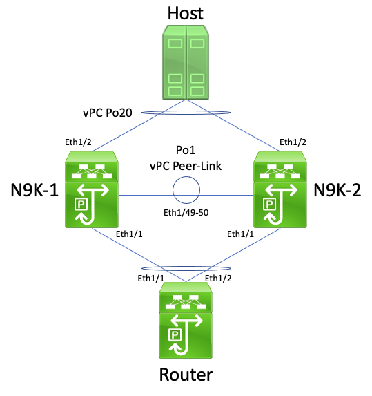
In this topology, Nexus switches N9K-1 and N9K-2 are vPC peers within a vPC domain where the vPC Peer Gateway enhancement is not enabled. Interface Po1 is the vPC Peer-Link. A router with a hostname of Router is connected via vPC Po10 to N9K-1 and N9K-2. A host is connected to N9K-1 and N9K-2 via vPC Po20. The Po10 interface of the router is a routed port-channel that is activated under a unicast routing protocol. N9K-1 and N9K-2 both have SVI interfaces activated under the same unicast routing protocol and are in the same broadcast domain as Router.
Unicast routing protocol adjacencies over a vPC without the vPC Peer Gateway enhancement enabled are not supported because the ECMP hashing decision of the vPC-connected router and its Layer 2 port-channel hashing decision can differ. In this topology, routing protocol adjacencies would successfully form between Router, N9K-1, and N9K-2. Consider the flow of traffic between Router and Host. Data plane traffic traversing Router destined to Host can be rewritten with a destination MAC address belonging to N9K-1's SVI MAC address (due to the ECMP hashing decision made by the router), but egress out of interface Ethernet1/2 (due to the Layer 2 port-channel hashing decision made by the router).
N9K-2 receives this packet and forward it across the vPC Peer-Link, since the destination MAC address belongs to N9K-1 and the vPC Peer Gateway enhancement (which allows N9K-2 to route the packet on behalf of N9K-1) is not enabled. N9K-1 receives this packet on the vPC Peer-Link and recognizes that it would need to forward the packet out of its Ethernet1/2 in vPC Po20. This violates the vPC Loop Avoidance rule, so N9K-1 drops the packet in hardware. As a result, you can observe connectivity issues or packet loss for some flows that traverse the vPC domain in this topology.
You can resolve this issue by enabling the vPC Peer Gateway enhancement with the peer-gateway vPC domain configuration command, then enabling the Routing/Layer 3 over vPC enhancement with the layer3 peer-router vPC domain configuration command. To minimize disruption, you need to enable both vPC enhancements in rapid succession so that the failure scenario described in the Unicast Routing Protocol Adjacencies over a vPC with vPC Peer Gateway does not have time to occur.
Unicast Routing Protocol Adjacencies over a vPC with vPC Peer Gateway
Consider the topology shown here:
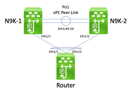
In this topology, Nexus switches N9K-1 and N9K-2 are vPC peers within a vPC domain where the vPC Peer Gateway enhancement is enabled. Interface Po1 is the vPC Peer-Link. A router with a hostname of Router is connected via vPC Po10 to N9K-1 and N9K-2. The Po10 interface of the router is a routed port-channel that is activated under a unicast routing protocol. N9K-1 and N9K-2 both have SVI interfaces activated under the same unicast routing protocol and are in the same broadcast domain as Router.
Unicast routing protocol adjacencies over a vPC with the vPC Peer Gateway enhancement enabled are not supported because the vPC Peer Gateway enhancement can prevent unicast routing protocol adjacencies from forming between the vPC-connected router and both vPC peers. In this topology, a routing protocol adjacency between Router and N9K-1 or N9K-2 can fail to come up as expected depending on how the unicast routing protocol packets originated by Router to either N9K-1 or N9K-2 hash across vPC Po10.
All routers are able to send and receive link-local multicast routing protocol packets (commonly called "Hello" packets) without issue, as these packets are flooded to the vPC VLAN successfully. However, consider a scenario where a unicast routing protocol packet sourced from Router destined to N9K-1 egresses Ethernet1/2 towards N9K-2 due to the Layer 2 port-channel hashing decision of the router. This packet is destined to N9K-1's SVI MAC address, but ingress N9K-2's Ethernet1/1 interface. N9K-2 sees that the packet is destined to N9K-1's SVI MAC address, which is installed in N9K-2's MAC address table with the "G", or "Gateway", flag due to the vPC Peer Gateway enhancement being enabled. As a result, N9K-2 attempts to locally route the unicast routing protocol packet on behalf of N9K-1.
However, by routing the packet, the Time to Live (TTL) of the packet is decremented, and the TTL of most unicast routing protocol packets is 1. As a result, the TTL of the packet is decremented to 0 and dropped by N9K-2. From N9K-1's perspective, N9K-1 is receiving link-local multicast routing protocol packets from Router and is able to send unicast routing protocol packets to Router, but is not receiving unicast routing protocol packets from Router. As a result, N9K-1 tears down the routing protocol adjacency with Router and restart its local finite state machine for the routing protocol. Similarly, Router restarts its local finite state machine for the routing protocol.
You can resolve this issue by enabling the Routing/Layer 3 over vPC enhancement with the layer 3 peer-router vPC domain configuration command. This enables unicast routing protocol packets with a TTL of 1 to be forwarded across the vPC Peer-Link without decrementing the TTL of the packet. As a result, unicast routing protocol adjacencies can be formed over a vPC or vPC VLAN without issue.
Unicast Routing Protocol Adjacencies over a vPC VLAN without vPC Peer Gateway
Consider the topology shown here:
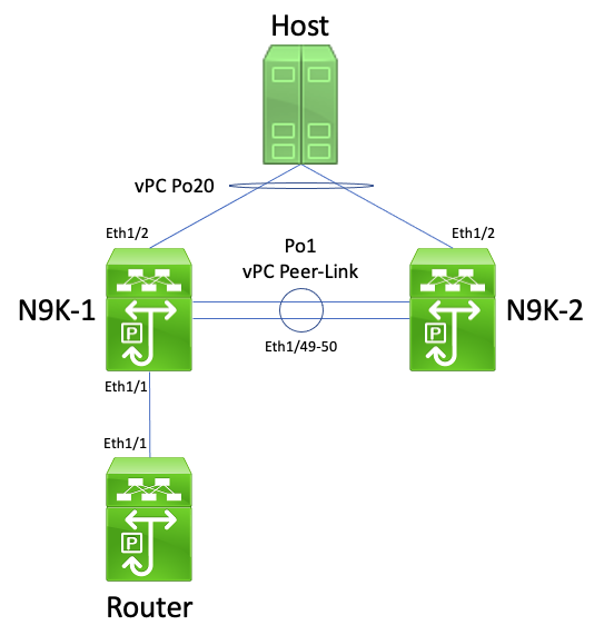
In this topology, Nexus switches N9K-1 and N9K-2 are vPC peers within a vPC domain where the vPC Peer Gateway enhancement is not enabled. Interface Po1 is the vPC Peer-Link. A router with a hostname of Router is connected via Ethernet1/1 to N9K-1's Ethernet1/1. The Ethernet1/1 interface of the router is a routed interface that is activated under a unicast routing protocol. N9K-1 and N9K-2 both have SVI interfaces activated under the same unicast routing protocol and are in the same broadcast domain as Router.
Unicast routing protocol adjacencies over a vPC VLAN without the vPC Peer Gateway enhancement enabled are not supported because the ECMP hashing decision of the vPC VLAN-connected router can cause N9K-2 to drop data plane traffic for violating the vPC Loop Avoidance rule. In this topology, routing protocol adjacencies would successfully form between Router, N9K-1, and N9K-2. Consider the flow of traffic between Router and Host. Data plane traffic traversing Router destined to Host can be rewritten with a destination MAC address belonging to N9K-2's SVI MAC address (due to the ECMP hashing decision made by the router) and egress out of interface Ethernet1/1 to N9K-1.
N9K-1 receives this packet and forward it across the vPC Peer-Link, since the destination MAC address belongs to N9K-2 and the vPC Peer Gateway enhancement (which allows N9K-1 to route the packet on behalf of N9K-2) is not enabled. N9K-2 receives this packet on the vPC Peer-Link and recognizes that it would need to forward the packet out of its Ethernet1/2 in vPC Po20. This violates the vPC Loop Avoidance rule, so N9K-2 drops the packet in hardware. As a result, you can observe connectivity issues or packet loss for some flows that traverse the vPC domain in this topology.
You can resolve this issue by enabling the vPC Peer Gateway enhancement with the peer-gateway vPC domain configuration command, then enabling the Routing/Layer 3 over vPC enhancement with the layer3 peer-router vPC domain configuration command. To minimize disruption, you need to enable both vPC enhancements in rapid succession so that the failure scenario described in the Unicast Routing Protocol Adjacencies over a vPC with vPC Peer Gateway does not have time to occur.
Unicast Routing Protocol Adjacencies over a vPC VLAN with vPC Peer Gateway
Consider the topology shown here:
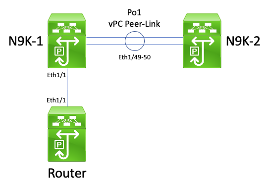
In this topology, Nexus switches N9K-1 and N9K-2 are vPC peers within a vPC domain where the vPC Peer Gateway enhancement is enabled. Interface Po1 is the vPC Peer-Link. A router with a hostname of Router is connected via Ethernet1/1 to N9K-1's Ethernet1/1. The Ethernet1/1 interface of the router is a routed interface that is activated under a unicast routing protocol. N9K-1 and N9K-2 both have SVI interfaces activated under the same unicast routing protocol and are in the same broadcast domain as Router.
Unicast routing protocol adjacencies over a vPC VLAN with the vPC Peer Gateway enhancement enabled are not supported because the vPC Peer Gateway enhancement prevents unicast routing protocol adjacencies from forming between the vPC VLAN-connected router and the vPC peer that the vPC VLAN-connected router is not directly connected to. In this topology, a routing protocol adjacency between Router and N9K-2 fails to come up as expected as a result of N9K-1 routing unicast routing protocol packets destined to N9K-2's SVI MAC address due to the vPC Peer Gateway enhancement being enabled. Since the packets are being routed, their Time To Live (TTL) must be decremented. Unicast routing protocol packets typically have a TTL of 1, and a router that decrements the TTL of a packet to 0 must drop that packet.
All routers are able to send and receive link-local multicast routing protocol packets (commonly called "Hello" packets) without issue, as these packets are flooded to the vPC VLAN successfully. However, consider a scenario where a unicast routing protocol packet sourced from Router destined to N9K-2 egresses Ethernet1/1 towards N9K-1. This packet is destined to N9K-2's SVI MAC address, but ingress N9K-1's Ethernet1/1 interface. N9K-1 sees that the packet is destined to N9K-2's SVI MAC address, which is installed in N9K-1's MAC address table with the "G", or "Gateway", flag due to the vPC Peer Gateway enhancement being enabled. As a result, N9K-1 attempts to locally route the unicast routing protocol packet on behalf of N9K-2.
However, by routing the packet, the TTL of the packet is decremented, and the TTL of most unicast routing protocol packets is 1. As a result, the TTL of the packet is decremented to 0 and dropped by N9K-1. From N9K-2's perspective, N9K-2 is receiving link-local multicast routing protocol packets from Router and is able to send unicast routing protocol packets to Router, but is not receiving unicast routing protocol packets from Router. As a result, N9K-2 tears down the routing protocol adjacency with Router and restart its local finite state machine for the routing protocol. Similarly, Router restarts its local finite state machine for the routing protocol.
You can resolve this issue by enabling the Routing/Layer 3 over vPC enhancement with the layer 3 peer-router vPC domain configuration command. This enables unicast routing protocol packets with a TTL of 1 to be forwarded across the vPC Peer-Link without decrementing the TTL of the packet. As a result, unicast routing protocol adjacencies can be formed over a vPC or vPC VLAN without issue.
Unicast Routing Protocol Adjacencies over Back-to-Back vPC with vPC Peer Gateway
Consider the topology shown here:
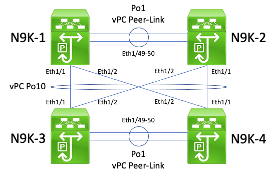
In this topology, Nexus switches N9K-1 and N9K-2 are vPC peers within a vPC domain where the vPC Peer Gateway enhancement is enabled. Nexus switches N9K-3 and N9K-4 are vPC peers within a vPC domain where the vPC Peer Gateway enhancement is enabled. Both vPC domains are connected to each other through a back-to-back vPC Po10. All four switches have SVI interfaces activated under a unicast routing protocol and are in the same broadcast domain.
Unicast routing protocol adjacencies across back-to-back vPCs with the vPC Peer Gateway enhancement enabled are not supported because the vPC Peer Gateway enhancement can prevent unicast routing protocol adjacencies from forming between one vPC domain and another vPC domain. In this topology, a routing protocol adjacency between N9K-1 and either N9K-3 or N9K-4 (or both) can fail to come up as expected. Similarly, a routing protocol adjacency between N9K-2 and either N9K-3 or N9K-4 (or both) can fail to come up as expected. This is because unicast routing protocol packets can be destined to one router (for example, N9K-3) but be forwarded to a different router (for example, N9K-4) based on the Layer 2 port-channel hashing decision of the originating router.
The root cause of this issue is identical to the root cause described in the Unicast Routing Protocol Adjacencies over a vPC with vPC Peer Gateway section of this document. You can resolve this issue by enabling the Routing/Layer 3 over vPC enhancement with the layer 3 peer-router vPC domain configuration command. This enables unicast routing protocol packets with a TTL of 1 to be forwarded across the vPC Peer-Link without decrementing the TTL of the packet. As a result, unicast routing protocol adjacencies can be formed over a back-to-back vPC without issue.
OSPF Adjacencies over vPC with vPC Peer Gateway where Prefix is Present in OSPF LSDB but not in Routing Table
Consider the topology shown here:
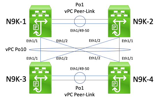
In this topology, Nexus switches N9K-1 and N9K-2 are vPC peers within a vPC domain where the vPC Peer Gateway enhancement is enabled. Nexus switches N9K-3 and N9K-4 are vPC peers within a vPC domain where the vPC Peer Gateway enhancement is enabled. Both vPC domains are connected to each other through a back-to-back vPC Po10. All four switches have SVI interfaces activated under a unicast routing protocol and are in the same broadcast domain. N9K-4 is the OSPF Designated Router (DR) for the broadcast domain, while N9K-3 is the OSPF Backup Designated Router (BDR) for the broadcast domain.
In this scenario, an OSPF adjacency between N9K-1 and N9K-3 transitions to a FULL state due to unicast OSPF packets egressing Ethernet1/1 of both switches. Similarly, an OSPF adjacency between N9K-2 and N9K-3 transitions to a FULL state due to unicast OSPF packets egressing Ethernet1/2 of both switches.
However, an OSPF adjacency between N9K-1 and N9K-4 is stuck in an EXSTART or EXCHANGE state due to unicast OSPF packets egressing Ethernet1/1 of both switches and being dropped by N9K-2 and N9K-4 as described in the Unicast Routing Protocol Adjacencies over Back-to-Back vPC with vPC Peer Gateway section of this document. Similarly, an OSPF adjacency between N9K-2 and N9K-4 is stuck in an EXSTART or EXCHANGE state due to unicast OSPF packets egressing Ethernet1/2 of both switches and being dropped by N9K-1 and N9K-3 as described in the Unicast Routing Protocol Adjacencies over Back-to-Back vPC with vPC Peer Gateway section of this document.
As a result, N9K-1 and N9K-2 are in a FULL state with the BDR for the broadcast domain, but are in an EXSTART or EXCHANGE state with the DR for the broadcast domain. Both the DR and BDR of a broadcast domain retain a full copy of the OSPF Link State Data Base (LSDB), but OSPF DROTHER routers must be in a FULL state with the DR for the broadcast domain in order to install prefixes learned via OSPF from either the DR or the BDR. As a result, both N9K-1 and N9K-2 appear to have prefixes learned from N9K-3 and N9K-4 present in the OSPF LSDB, but those prefixes are not installed in the unicast routing table until N9K-1 and N9K-2 transition to a FULL state with N9K-4 (the DR for the broadcast domain).
You can resolve this issue by enabling the Routing/Layer 3 over vPC enhancement with the layer 3 peer-router vPC domain configuration command. This enables unicast routing protocol packets with a TTL of 1 to be forwarded across the vPC Peer-Link without decrementing the TTL of the packet. As a result, unicast routing protocol adjacencies can be formed over a back-to-back vPC without issue. As a result, N9K-1 and N9K-2 transitions to a FULL state with N9K-4 (the DR for the broadcast domain) and installs prefixes learned from N9K-3 and N9K-4 via OSPF into their respective unicast routing tables successfully.
Related Information
- Cisco Nexus 9000 Series NX-OS Interfaces Configuration Guide, Release 10.5(x)
- Cisco Nexus 9000 Series NX-OS Interfaces Configuration Guide, Release 10.4(x)
- Cisco Nexus 9000 Series NX-OS Interfaces Configuration Guide, Release 10.3(x)
- Cisco Nexus 9000 Series NX-OS Interfaces Configuration Guide, Release 10.2(x)
- Cisco Nexus 9000 Series NX-OS Interfaces Configuration Guide, Release 10.1(x)
- Cisco Nexus 9000 Series NX-OS Interfaces Configuration Guide, Release 9.3(x)
- Cisco Nexus 9000 Series NX-OS Interfaces Configuration Guide, Release 9.2(x)
- Cisco Nexus 9000 Series NX-OS Interfaces Configuration Guide, Release 7.x
- Cisco Nexus 7000 Series NX-OS Interfaces Configuration Guide 8.x
- Cisco Nexus 7000 Series NX-OS Interfaces Configuration Guide 7.x
- Design and Configuration Guide: Best Practices for Virtual Port Channels (vPC) on Cisco Nexus 7000 Series Switches
- Supported Topologies for Routing over Virtual Port Channel on Nexus Platforms
Revision History
| Revision | Publish Date | Comments |
|---|---|---|
5.0 |
05-Dec-2024 |
Fixed headers and links, machine translation and SEO optimization |
4.0 |
12-Dec-2022 |
Recertification |
3.0 |
29-Oct-2021 |
Corrected typo in vPC Peer Gateway failure scenario. |
2.0 |
15-Sep-2021 |
Add note about how "peer-gateway exclude-vlan" vPC domain configuration command is not supported on Nexus 9000 series switches. |
1.0 |
30-Jul-2021 |
Initial Release |
Contributed by Cisco Engineers
- Mel LlanosCisco Engineering
- Christopher HartCisco TAC Engineer
Contact Cisco
- Open a Support Case

- (Requires a Cisco Service Contract)
 Feedback