Configuring DLSw Local-Switching from SDLC to Ethernet
Available Languages
Contents
Introduction
This document provides a sample configuration for configuring data-link switching (DLSw) local-switching from Synchronous Data Link Control (SDLC) to Ethernet.
Prerequisites
Requirements
There are no specific requirements for this document.
Components Used
This document is not restricted to specific software and hardware versions.
The information in this document was created from the devices in a specific lab environment. All of the devices used in this document started with a cleared (default) configuration. If your network is live, make sure that you understand the potential impact of any command.
Conventions
For more information on document conventions, refer to Cisco Technical Tips Conventions.
Configure
In this section, you are presented with the information to configure the features described in this document.
Network Diagram
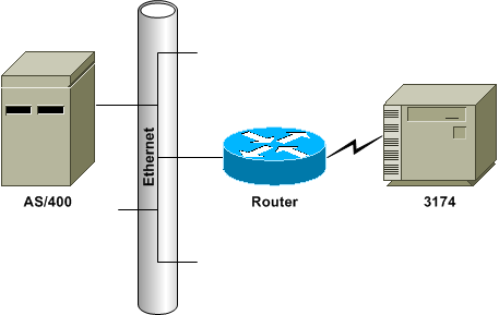
This document uses this network setup:

Configurations
This document uses these configurations:
| SDLC PU 2.0 to Ethernet-Attached Host Device |
|---|
dlsw local
dlsw bridge-group 1

interface ethernet0
    bridge-group 1

interface serial0
    encapsulation sdlc
    clock rate 9600
    sdlc role primary
    sdlc vmac 4000.3174.0000
    sdlc address 01
    sdlc xid 01 05d2006
    sdlc partner 4000.0400.1111 01
sdlc dlsw 01 |
Configuration Notes
For SDLC-attached devices, DLSw local-switching can be used to provide Logical Link Control 2 (LLC2) connectivity to a device on the Ethernet. The SDLC partner address references the MAC address with which the 3174 is to be in session. In this configuration, the SDLC partner address is 4000.0400.1111 and is in non-canonical Token Ring format. The MAC address is bitswapped to the canonical Ethernet format of 0200.2000.8888. This is the actual MAC address of the AS/400.
The exchange identification (XID) configured on the serial interface is for sample configuration purposes; the actual XID configured should match host definitions. Clock rate is defined on the serial interface of the router, if the router is the data circuit-terminating equipment (DCE) device and if it has the appropriate cable attached. The SDLC address shown in this configuration is 01; the actual SDLC address should match the controller???s definition for it. The actual MAC address used is the SDLC Virtual Media Access Control (VMAC) address combined with the SDLC address. In this sample configuration, the VMAC is 4000.3174.0000 and the SDLC address is inserted into the last byte of the VMAC to become 4000.3174.0001. When this is bitswapped to Ethernet, it becomes 0200.8c2e.0080.
| SDLC PU 2.1 to Ethernet-Attached Host Device |
|---|
dlsw local
dlsw bridge-group 1

interface ethernet0
    bridge-group 1

interface serial0
    encapsulation sdlc
    clock rate 9600
    sdlc role prim-xid-poll
    sdlc vmac 4000.3174.0000
    sdlc address 01
    sdlc partner 4000.0400.1111 01
sdlc dlsw 01 |
Configuration Notes
For a Physical Unit type 2.1 (PU 2.1) device, the XID is not configured on the router, nor is it answered by the router. The router sends the XID to the SDLC-attached device, and it and the host device are responsible for XID negotiation. The configuration for a PU 2.1 device is similar, with two differences: the SDLC XID command is not configured in the router, and the command becomes sdlc prim-xid-poll. With sdlc role prim-xid-poll configured on the router, the SDLC device is polled with XIDs instead of with Set Normal Response Modes (SNRMs).
Alternatively, if the line is multidropped and it includes PU 2.0 devices, you can issue the sdlc role primary command and specify xid-poll in the sdlc address command (for example, sdlc address c1 xid-poll). Refer to DLSw for Multidrop SDLC with PU 2.1 and PU 2.0 for more information on how to configure an SDLC interface.
Verify
There is currently no verification procedure available for this configuration.
Troubleshoot
This section provides information that you can use to troubleshoot your configuration.
Because this is known as a DLSw local circuit and not known over an IP cloud, you must issue the show dlsw local-circuit command. When the connection initializes, the router sends a SNRM frame to the controller. The controller should respond with an unnumbered acknowledgement (UA) frame. At this point, the show dlsw reachability command output shows the SDLC VMAC address in local reachability. Next, a test poll frame is sent to the host device.
Upon a test final response from the host device, the router???s dlsw reachability cache will have found each MAC address attempting to reach a session. The router now sends the XID poll frame to the host and should receive a final XID from the host. The router then sends a set asynchronous balanced mode extended (SABME) and should receive a UA back. Now, the DLSw circuit is connected. During the test poll and XID negotiation period, the router continuously sends receive not ready (RNR) frames to the controller. Once the final XID is received and is correct, the router sends receive ready (RR) to the controller, indicating that the session is up and OK to send data.
If the show dlsw local-circuit command output indicates a CKT_ESTABLISHED state, the XID negotiation is not completing successfully, and the XID and PU status on the host device should be examined for correctness and connectability. When the show dlsw reachability command output shows the MAC address of the host device as SEARCHING, the router is sending test poll frames to the host device and is not receiving test finals in return. All show dlsw commands will show the MAC address in Token Ring format. Ensure that the host device MAC address is connected.
Related Information
Revision History
| Revision | Publish Date | Comments |
|---|---|---|
1.0 |
09-Sep-2005 |
Initial Release |
 Feedback