Data Link Switching Plus
Available Languages
Contents
Introduction
Data-link switching (DLSw) is a standard implemented by IBM that supports the transport of Logical Link Control (LLC) over WANs. DLSw is a more elaborate form of remote source-route bridging (RSRB) and is more specific as to what it can or cannot bridge. DLSw requires that the router transports a valid LLC2 session or a NetBIOS session.
Cisco routers implement RFC 1795 (DSLw standard) and 2166 (DLSw version 2). Also, DLSw implements more features for broadcast control and transports less information across the WAN than other methods.
Prerequisites
Requirements
There are no specific requirements for this document.
Components Used
This document is not restricted to specific software and hardware versions.
Conventions
Refer to Cisco Technical Tips Conventions for more information on document conventions.
General Commands
This section covers important DLSw commands, commands for configuring DLSw, and commands for troubleshooting DLSw.
source-bridge ring-group
The first step in configuring DLSw is to add the source-bridge ring-group command. This connects the Token Ring interfaces performing source-route bridging (SRB).
| Task | Command |
|---|---|
| Define a ring group. | source-bridge ring-group ring-group [virtual-mac-address] |
Note: When performing DLSw on a router that only has Ethernet interfaces, there is no need to set up a ring-group.
Define the Local Peer Identification
The next option is to define the local peer identification. This is an IP address in the same box. This basically starts DLSw in the router.
| Task | Command |
|---|---|
| Define the DLSw+ local peer. | dlsw local-peer [peer-id ip-address] [group group] [border] [cost cost] [lf size] [keepalive seconds] [passive] [promiscuous] [biu-segment] |
The most basic option in configuring DLSw is to establish the local peer-id ip-address. These are descriptions of the command parameters:
-
group and border— These commands are issued together to create border peers in the network.
-
cost— This command is issued when there are multiple paths to the same location. This command tells the router how to reach these remote sites using the lowest-cost path first.
-
lf— This command determines the largest frame size that this peer can handle. The frame sizes can be:
-
516-516 byte maximum frame size
-
1470-1470 byte maximum frame size
-
1500-1500 byte maximum frame size
-
2052-2052 byte maximum frame size
-
4472-4472 byte maximum frame size
-
8144-8144 byte maximum frame size
-
11407-11407 byte maximum frame size
-
11454-11454 byte maximum frame size
-
17800-17800 byte maximum frame size
-
-
keepalive— This command defines the interval in-between keepalive packets. The interval can range from 0 to 1200 seconds. It is usually set to 0 when configuring DLSw for Dial-on-Demand Routing (DDR).
-
passive— This command configures the router to not initiate a peer startup from the router.
-
promiscuous— This command means that the router accepts connections from any remote peer requesting a peer startup. This command is useful in large sites that have many peers, because you do not have to define all the remote peers in the core router.
-
biu-segment— This command is an option for DLSw that permits DLSw to control the segment size higher in the System Network Architecture (SNA) layers. This command enables the end stations believe they can send larger amounts of data.
Define the Remote Peer
After defining the local peer, you define the remote peer. You can define three types of peers: TCP, Fast-Sequenced Transport (FST), and direct High-Level Link Control (HDLC) and Frame Relay. These are explanations of the commands issued to define the remote peer:
| Task | Command |
|---|---|
| Direct encapsulation over Frame Relay | dlsw remote-peer list-number frame-relay interface serial number dlci-number [backup-peer ip-address] [bytes-netbios-out bytes-list-name] [cost cost] [dest-mac mac-address] [dmac-output-list access-list-number] [host-netbios-out host-list-name] [keepalive seconds] [lf size] [linger minutes] [lsap-output-list list] [pass-thru] |
| Direct encapsulation over HDLC | dlsw remote-peer list-number interface serial number [backup-peer ip-address] [bytes-netbios-out bytes-list-name] [cost cost] [dest-mac mac-address] [dmac-output-list access-list-number] [host-netbios-out host-list-name] [keepalive seconds] [lf size] [linger minutes] [lsap-output-list list] [pass-thru] |
| FST | dlsw remote-peer list-number fst ip-address [backup-peer ip-address] [bytes-netbios-out bytes-list-name] [cost cost] [dest-mac mac-address] [dmac-output-list access-list-number] [host-netbios-out host-list-name] [keepalive seconds] [lf size] [linger minutes] [lsap-output-list list] [pass-thru] |
| TCP | dlsw remote-peer list-number tcp ip-address [backup-peer ip-address] [bytes-netbios-out bytes-list-name] [cost cost] [dest-mac mac-address] [dmac-output-list access-list-number] [dynamic] [host-netbios-out host-list-name] [inactivity minutes] [keepalive seconds] [lf size] [linger minutes] [lsap-output-list list] [no-llc minutes] [priority] [tcp-queue-max size] [timeout seconds][v2-single-tcp] |
These are the descriptions of the command options:
-
backup peer— This command option defines the peer that backs up this peer in the event that the first peer fails.
-
cost— This command option defines the cost of this peer. This command is used when there are multiple paths to a destination and when you need a preferred-capable scenario.
-
dest-mac, dynamic, no-llc and inactivity— These command options are discussed in the Backup/Cost Peer section of this document.
-
dmac-output-list— This command option is issued to define an access list that tells the router which remote destination MAC addresses you permit, or deny, explorer traffic.
-
host-netbios-out— This command option is issued to apply NetBIOS host filter names.
-
keepalive— This command option is issued to determine the interval in seconds between keepalives. It is used mostly for DDR setups.
-
lf— This command option specifies the largest size allowed for the peer.
-
linger— This command option specifies the amount of time that the router leaves the backup peer open that becomes active (because of primary failure) after the primary link becomes active again.
-
priority— This command option creates multiple peers for prioritization of DLSw traffic.
-
tcp-queue-max— This command option changes the default value of 200 for the TCP queues.
-
timeout— This command option is the number of seconds that TCP waits for an acknowledgment before tearing down the connection.
-
V2-single-tcpM— This command option is designed for use in Network Address Translation (NAT) environments. Each peer thinks it has the higher IP addresss to prevent each peer from tearing down one of the TCP connections.
Timers Used in DLSw
These are explanations of the timers used in DLSw:
| Parameter | Description |
|---|---|
| icannotreach-block-time | Cache life of unreachable resource, during which searches for that resource are blocked. The valid range is 1 to 86400 seconds. The default is 0 (disabled) |
| netbios-cache-timeout | Cache life of NetBIOS name location for both local and remote reachability cache. The valid range is 1 to 86400 seconds. The default is 16 minutes. |
| netbios-explorer-timeout | Length of time that the IOS® software waits for an explorer response before marking a resource unreachable (LAN and WAN). The valid range is 1 to 86400 seconds. The default is 6 seconds. |
| netbios-retry-interval | NetBIOS explorer retry interval (LAN only). The valid range is 1 to 86400 seconds. The default is 1 second. |
| netbios-verify-interval | Interval between the creation of a cache entry and when the entry is marked as stale. If a search request comes in for a stale cache entry, a directed verify query is sent to ensure that it still exists. The valid range is 1 to 86400 seconds. The default is 4 minutes. |
| sna-cache-timeout | Length of time that a SNA MAC/Service Access Point (SAP) location cache entry exists before it is discarded (local and remote). The valid range is 1 to 86400 seconds. The default is 16 minutes. |
| sna-explorer-timeout | Length of time that the IOS software waits for an explorer response before marking a resource unreachable (LAN and WAN). The valid range is 1 to 86400 seconds. The default is 3 minutes. |
| sna-retry-interval | Interval between SNA explorer retries (LAN). The valid range is 1 to 86400 seconds. The default is 30 seconds. |
| sna-verify-interval | Interval between the creation of a cache entry and when the entry is marked as stale. If a search request comes in for a stale cache entry, a directed verify query is sent to assure that it still exists. The valid range is 1 to 86400 seconds. The default is 4 minutes. |
| explorer-wait-time | Time, in seconds, that the router waits for all explorers to return before determining which peer to use. |
These parameters are very useful. For example, you can change the interval in seconds that the router sends an explorer. This helps reduce the quantity of explorers in the network by increasing the time between them. Also, you can change the values at which the router times out the cache entries.
Additional DLSw Commands
These are additional important DLSw commands:
-
dlsw allroute-sna/netbios— This command is issued to change the behavior of DLSw so that all route explorers are used instead of single route explorers.
-
dlsw bridge-group— This command is issued to tie transparently bridged domains with DLSw. It is used extensively when configuring NetBIOS with Ethernet.
-
dlsw explorerq-depth— This command sets the value of the DLSw explorer queue. This command is issued after the regular source-bridge explorer-queue command, but it refers to all the CANUREACH (CUR) frames that need to be processed. This command is important because it covers the packets from the Ethernet, even though it is not covered in the source-bridge explorerq-depth command. Refer to Understanding and Troubleshooting Source-Route Bridging for more information on this command.
show Commands
The show commands and outputs described in this section are useful when troubleshooting DLSw.
show dlsw peer
This command provides information about peers. Each remote peer configured is displayed here, including the quantity of transmitted and received packets.
Peers:                state     pkts_rx   pkts_tx  type  drops ckts TCP   uptime
 TCP 5.5.5.1         CONNECT          2         2  conf      0    0   0 00:00:06
These are the possible states:
-
CONNECT— This state means that DLSw peer is up and running.
-
DISCONNECT- This state means that the peer is down or not connected.
-
CAP_EXG— This state means that DLSw is in capabilities exchange with the remote peer.
-
WAIT_RD— This state is the final step in starting up the peer. This peer is waiting for the remote peer to open the read port. Refer to the debugging section of this document for more information about when the peer starts up and issuing the debug dlsw peer command.
-
WAN_BUSY— This state means that the TCP outbound queue is full, and the packet cannot be transmitted.
The show dlsw peer command also shows the number of drops, the quantity of circuits across the specific peer, the TCP queue, and the uptime. The drop counter increases for these reasons:
-
WAN interface is not up for a direct peer.
-
DLSw tries to send a packet before the peer is fully connected (waiting for TCP event or capabilities event). Outbound TCP queue full.
-
FST sequence number count mismatch.
-
Cannot get buffer to slow switch FST packet.
-
CiscoBus controller failure on high end; cannot move packet from receive buffer to transmit buffer, or vice versa.
-
Destination IP address of FST packet does not match local peer ID.
-
WAN interface not up for an FST peer.
-
No SRB route cache command configured.
-
Madge ring buffer is full on low-end systems: WAN feeding LAN too fast.
show dlsw capabilities
DLSw: Capabilities for peer 5.5.5.1(2065)
  vendor id (OUI)         : '00C' (cisco)
  version number          : 1
  release number          : 0
  init pacing window      : 20
  unsupported saps        : none
  num of tcp sessions     : 1
  loop prevent support    : no
  icanreach mac-exclusive : no
  icanreach netbios-excl. : no
  reachable mac addresses : none
  reachable netbios names : none
  cisco version number    : 1
  peer group number       : 0
  border peer capable     : no
  peer cost               : 3
  biu-segment configured  : no
  local-ack configured    : yes
  priority configured     : no
  version string          :
Cisco Internetwork Operating System Software
IOS (tm) 4500 Software (C4500-J-M), Version 10.3(13), RELEASE SOFTWARE (fc2)
Copyright (c) 1986-1996 by cisco Systems, Inc.
show dlsw reachability
DLSw MAC address reachability cache list
Mac Addr        status     Loc.    peer/port            rif
0800.5a0a.c51d  FOUND      LOCAL   TokenRing3/0     06B0.0021.00F0
0800.5a49.1e38  FOUND      LOCAL   TokenRing3/0     06B0.0021.00F0
0800.5a95.3a13  FOUND      REMOTE  5.5.5.1(2065)

DLSw NetBIOS Name reachability cache list
NetBIOS Name    status     Loc.    peer/port            rif
PIN-PIN         FOUND      LOCAL   TokenRing3/0     06B0.0021.00F0
QUENEPA         FOUND      LOCAL   TokenRing3/0     06B0.0021.00F0
WIN95           FOUND      REMOTE  5.5.5.1(2065)
The status field is the most important part of the show dlsw reach command. These are the possible statuses:
-
FOUND— The router has located the device.
-
SEARCHING— The router is searching for the resource.
-
NOT_FOUND— Negative caching is on, and the station has not responded to queries.
-
UNCONFIRMED— Station is configured, but DLSw has not verified it.
-
VERIFY— Verifying cache information because cache is going stale, or the user configuration is being verified.
show dlsw circuit
Index           local addr(lsap)    remote addr(dsap)  state
1622193728      4001.68ff.0001(04)  4000.0000.0001(04) CONNECTED
        PCEP: 60A545B4   UCEP: 60B0B640
        Port:To3/0          peer 5.5.5.1(2065)
        Flow-Control-Tx CW:20, Permitted:32; Rx CW:20, Granted:32
        RIF = 06B0.0021.00F0
When issuing the show dlsw circuit command, pay attention to the flow control. Flow control exists at a per-circuit basis. This is a communication that occurs while the two DLSw peers assign the circuit a window of possible transfer. This value increases and decreases depending on the amount of traffic that the circuit is trying to move through. The value can change depending on the congestion of the cloud.
The show dlsw circuit command is more extensive as of IOS 11.1. The command now permits you to look at the DLSw circuit on a service access point (SAP) value or MAC value, which simplifies locating circuits when troubleshooting. This is a sample output:
ibu-7206#sh dlsw cir
Index           local addr(lsap)    remote addr(dsap)  state
1622193728      4001.68ff.0001(04)  4000.0000.0001(04) CONNECTED
ibu-7206#sh dls cir det ?
  <0-4294967295>  Circuit ID for a specific remote circuit
  mac-address     Display all remote circuits using a specific MAC
  sap-value       Display all remote circuits using a specific SAP
  <cr>

ibu-7206#show dlsw circuit detail mac 4000.0000.0001
Index           local addr(lsap)    remote addr(dsap)  state
1622193728      4001.68ff.0001(04)  4000.0000.0001(04) CONNECTED
        PCEP: 60A545B4   UCEP: 60B0B640
        Port:To3/0          peer 5.5.5.1(2065)
        Flow-Control-Tx CW:20, Permitted:29; Rx CW:20, Granted:29
        RIF = 06B0.0021.00F0
241-00  4000.0000.0001(04)  4001.68ff.0000(04) CONNECTED
        Port:To0          peer 5.5.7.1(2065)
        Flow-Control-Tx CW:20, Permitted:27; Rx CW:20, Granted:27
        RIF = 0630.00F1.0010
s5e#sh cls
DLU user: DLSWDLU
      SSap:0x63       type:  llc0   class:0
        DTE:0800.5a95.3a13 0800.5a0a.c51d F0 F0
        T1 timer:0      T2 timer:0      Inact timer:0
        max out:0       max in:0        retry count:0
        XID retry:0     XID timer:0     I-Frame:0

        DTE:4000.0000.0001 4001.68ff.0000 04 04
        T1 timer:0      T2 timer:0      Inact timer:0
        max out:0       max in:0        retry count:0
        XID retry:0     XID timer:0     I-Frame:0
TokenRing0 DTE: 4000.0000.0001 4001.68ff.0000 04 04 state NORMAL
   V(S)=23, V(R)=23, Last N(R)=22, Local window=7, Remote Window=127
   akmax=3, n2=8, Next timer in 1240
   xid-retry timer      0/0       ack timer    1240/1000
   p timer              0/1000    idle timer  10224/10000
   rej timer            0/3200    busy timer      0/9600
   akdelay timer        0/100     txQ count       0/200
Troubleshooting
By default, DLSw terminates LLC sessions at the routers (local-ack). In addition, because it terminates the routing information field (RIF), there are other design issues to consider. The most common DLSw problems are described in this section.
Loops
One of the most important things to remember about DLSw is RIF termination. This is an issue because major loops in the network can easily be created. This diagram demonstrates a loop:
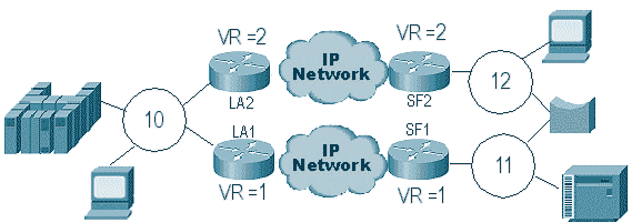
In this case, since DLSw terminates the RIF, the packet goes around indefinitely. This is because every time a CUR frame is sent from peer to peer, the receiving peer creates a new explorer (NO RIF) and sends it. The steps of the explorer are described:
-
The 3174 in ring 11 sends an explorer to reach the host.
-
Both SF1 and the bridge copy the frame.
-
SF1 creates a CUR frame to LA1 (its peer) to tell LA1 that the 3174 wants to reach the HOST.
-
SF2 receives the packet and does the same thing.
-
Now LA1 and LA2 create the explorer and send it to the ring.
-
LA1 and LA2 receive an explorer that each other created.
-
Now there is a dilemma, because each side believes that the 3174 is locally attached.
-
Each router has the 3174, both local and remote.
-
Now they send an Icanreach frame to SF1 and SF2, respectively, which creates a response from the host towards the 3174.
-
Both SF1 and SF2 put explorer response on the Token Ring and each learn that the MAC address of host is reachable locally and remotely.
-
DLSw reachability effectively firewalls against explorer looping indefinetly. However, with unnumbered information (UI) frames, this can loop, then drive CPU and line utilization up to 100%.
If this occurs, verify that the virtual ring in the routers are exactly the same on each side of the cloud, as displayed in this diagram:
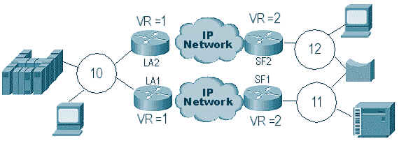
The routers on each side of this cloud have the exact same virtual ring number. This ensures that one of the routers sends an explorer that has already passed through the ring, then the router drops it. When LA1 generates an explorer for a CUR frame received by SF1, LA2 drops it because the explorer already passed through ring 1. In this scenario, it is important that the router has a different bridge configured if the packet is headed for the same ring, which is the case of the LA side of the network.
In an Ethernet version of the same scenario, you must disable a peer. An example is displayed in this diagram:
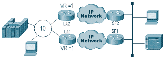
Because a packet on the Ethernet does not have a RIF, the router cannot determine if the broadcast, created by the other router on the LAN, is from the other router or from a originating station. With SNA, the packet is locally originated or remote. Because explorers from a Token Ring environment in effect have both source and destination MAC addresses, they are not a broadcast on the Ethernet, but a directed frame to a station from another.
What occurs in the preceding diagram is explained in these steps:
-
An explorer is sent from the 3174 to the host.
-
This explorer is accepted by both SF1 and SF2.
-
SF1 and SF2 each generate a CUR to the other side LA1 and LA2.
-
These generate an explorer that the host responds to; because it is a single-route explorer, it is responded to with an all-route explorer.
-
Both LA1 and LA2 create a CUR frame to SF1 and SF2, which create the packet for the 3174.
-
SF1 hears the MAC address of the HOST coming from the Ethernet and now believes that the HOST is located on the local LAN. But in the cache of SF1, the HOST id is responding from a remote peer.
-
This forces the router to have the HOST both local and remote, which means that DLSw is broken.
Backup/Cost Peers
Backup peers add fault tolerance to DLSw in the event that a peer is lost. This is usually set up in core environments so that when a core router fails, another router can accept the failing router. The configurations and the diagram in this section illustrate a backup peer setup.
| D3B |
|---|
Current configuration: ! version 11.1 service udp-small-servers service tcp-small-servers ! hostname d3b ! ! source-bridge ring-group 2 dlsw local-peer peer-id 1.1.14.1 cost 2 promiscuous ! interface Loopback0 ip address 1.1.14.1 255.255.255.0 ! interface Serial0 ip address 1.1.6.2 255.255.255.0 bandwidth 125000 clockrate 125000 ! interface TokenRing0 ip address 1.1.5.1 255.255.255.0 ring-speed 16 source-bridge 3 1 2 source-bridge spanning ! |
| D3C |
|---|
Current configuration: ! version 11.1 service udp-small-servers service tcp-small-servers ! hostname d3c ! ! source-bridge ring-group 2 dlsw local-peer peer-id 1.1.12.1 cost 4 promiscuous ! interface Loopback0 ip address 1.1.12.1 255.255.255.0 ! interface Serial0 ip address 1.1.4.1 255.255.255.0 bandwidth 500000 clockrate 500000 ! interface TokenRing0 ip address 1.1.5.2 255.255.255.0 ring-speed 16 source-bridge 3 2 2 source-bridge spanning ! |
| D3A |
|---|
Current configuration: ! version 11.1 service udp-small-servers service tcp-small-servers ! hostname d3a ! ! source-bridge ring-group 2 dlsw local-peer peer-id 1.1.13.1 dlsw remote-peer 0 tcp 1.1.14.1 dlsw remote-peer 0 tcp 1.1.12.1 dlsw timer explorer-wait-time 2 ! interface Loopback0 ip address 1.1.13.1 255.255.255.0 ! interface Serial0 ip address 1.1.6.1 255.255.255.0 bandwidth 500000 ! interface Serial1 ip address 1.1.4.2 255.255.255.0 bandwidth 125000 ! interface TokenRing0 ip address 1.1.1.1 255.255.255.0 ring-speed 16 source-bridge 3 1 2 source-bridge spanning ! |
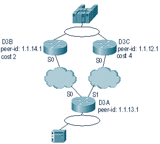
The first thing to remember about DLSw cost peers is that both peers are active. The router maintains only one backup peer. It can have two at the time if linger is configured. This is what occurred in the preceding diagram:
-
D3a receives an explorer and starts the process by sending a CUR frame to each remote peer.
-
D3B and D3C receive the CUR frames. Each generates an explorer to the host, which replies back to both D3B and D3C.
-
Both D3B and D3C respond back to D3A with Icanreach.
-
D3A sends the explorer response to the end station.
-
Remote station starts the dlsw circuit, with exchange identification (XID) for SNA and set asynchronous balanced mode extended (SABME) for NetBIOS.
-
D3A selects lower cost within reachability.
There is a timer in D3A that can be defined to tell the router how long to wait for all the explorers to return to D3A. This avoids problems with costs that can occur when the router uses the first explorer that comes back to it. Issue the dlsw timer explorer-wait-time <seconds> command to set this timer.
In addition, when performing border peers, DLSw sends only one CUR frame to the lowest cost peer. It behaves differently than it does when performing cost without border peers.
Backup peers operate a little differently. You specify the backup peer in the peer that is going to be backup for the specified peer. This means that the peer that has the backup statement is the backup peer itself.
Specify the linger option so that when the primary peer becomes operational again, the circuits cannot tear down immediately. This is useful if the primary peer varies up and down, because you do not want to use the faulty peer.
This demonstrates the configuration of backup peers:
| D3B |
|---|
Current configuration: ! version 11.1 service udp-small-servers service tcp-small-servers ! hostname d3b ! ! source-bridge ring-group 2 dlsw local-peer peer-id 1.1.14.1 promiscuous ! interface Loopback0 ip address 1.1.14.1 255.255.255.0 ! interface Serial0 ip address 1.1.6.2 255.255.255.0 bandwidth 125000 clockrate 125000 ! interface TokenRing0 ip address 1.1.5.1 255.255.255.0 ring-speed 16 source-bridge 3 1 2 source-bridge spanning ! |
| D3C |
|---|
Current configuration: ! version 11.1 service udp-small-servers service tcp-small-servers ! hostname d3c ! ! source-bridge ring-group 2 dlsw local-peer peer-id 1.1.12.1 promiscuous ! interface Loopback0 ip address 1.1.12.1 255.255.255.0 ! interface Serial0 ip address 1.1.4.1 255.255.255.0 bandwidth 500000 clockrate 500000 ! interface TokenRing0 ip address 1.1.5.2 255.255.255.0 ring-speed 16 source-bridge 3 2 2 source-bridge spanning ! |
| D3A |
|---|
Current configuration: ! version 11.1 service udp-small-servers service tcp-small-servers ! hostname d3a ! ! source-bridge ring-group 2 dlsw local-peer peer-id 1.1.13.1 dlsw remote-peer 0 tcp 1.1.14.1 dlsw remote-peer 0 tcp 1.1.12.1 backup-peer 1.1.14.1 linger 5 dlsw timer explorer-wait-time 2 ! interface Loopback0 ip address 1.1.13.1 255.255.255.0 ! interface Serial0 ip address 1.1.6.1 255.255.255.0 bandwidth 500000 ! interface Serial1 ip address 1.1.4.2 255.255.255.0 bandwidth 125000 ! interface TokenRing0 ip address 1.1.1.1 255.255.255.0 ring-speed 16 source-bridge 3 1 2 source-bridge spanning ! |
The peer is disconnected by issuing the show dlsw peer command:
d3a#sh dls peer
Peers:                state     pkts_rx   pkts_tx  type  drops ckts TCP   uptime
 TCP 1.1.14.1        CONNECT        464      1286  conf      0    0   0 03:17:02
 TCP 1.1.12.1        DISCONN          0         0  conf      0    0   -        -
Border Peers
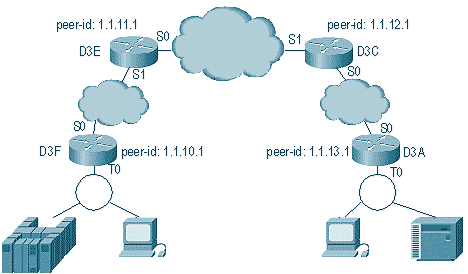
Border peers are an important DLSw feature because they solve the problem of broadcast control in a network. This example illustrates how border peers are configured and what occurs when a session comes up:
| D3E |
|---|
Current configuration: ! version 11.1 service udp-small-servers service tcp-small-servers ! hostname d3e ! ! dlsw local-peer peer-id 1.1.11.1 group 1 border promiscuous dlsw remote-peer 0 tcp 1.1.12.1 ! interface Loopback0 ip address 1.1.11.1 255.255.255.0 ! interface Serial0 ip address 1.1.3.1 255.255.255.0 ! interface Serial1 ip address 1.1.2.2 255.255.255.0 clockrate 500000 ! interface TokenRing0 ip address 10.17.1.189 255.255.255.0 ring-speed 16 ! router ospf 100 network 1.0.0.0 0.255.255.255 area 0 ! |
| D3C |
|---|
Current configuration: ! version 11.1 service udp-small-servers service tcp-small-servers ! hostname d3c ! ! dlsw local-peer peer-id 1.1.12.1 group 2 border promiscuous dlsw remote-peer 0 tcp 1.1.11.1 ! interface Loopback0 ip address 1.1.12.1 255.255.255.0 ! interface Serial0 ip address 1.1.4.1 255.255.255.0 no fair-queue clockrate 500000 ! interface Serial1 ip address 1.1.3.2 255.255.255.0 clockrate 500000 ! interface TokenRing0 no ip address shutdown ring-speed 16 ! router ospf 100 network 1.0.0.0 0.255.255.255 area 0 ! |
| D3F |
|---|
Current configuration: ! version 11.1 service udp-small-servers service tcp-small-servers ! hostname d3f ! ! source-bridge ring-group 2 dlsw local-peer peer-id 1.1.10.1 group 1 promiscuous dlsw remote-peer 0 tcp 1.1.11.1 dlsw peer-on-demand-defaults inactivity 1 ! interface Loopback0 ip address 1.1.10.1 255.255.255.0 ! interface Serial0 ip address 1.1.2.1 255.255.255.0 no fair-queue !! interface TokenRing0 ip address 1.1.1.1 255.255.255.0 ring-speed 16 source-bridge 1 1 2 source-bridge spanning ! router ospf 100 network 1.0.0.0 0.255.255.255 area 0 |
| D3A |
|---|
Current configuration: ! version 11.1 service udp-small-servers service tcp-small-servers ! hostname d3a ! ! source-bridge ring-group 2 dlsw local-peer peer-id 1.1.13.1 group 2 promiscuous dlsw remote-peer 0 tcp 1.1.12.1 dlsw peer-on-demand-defaults inactivity 1 ! interface Loopback0 ip address 1.1.13.1 255.255.255.0 ! interface Serial0 ip address 1.1.4.2 255.255.255.0 ! interface TokenRing0 ip address 1.1.5.1 255.255.255.0 ring-speed 16 source-bridge 3 1 2 source-bridge spanning ! router ospf 100 network 1.0.0.0 0.255.255.255 area 0 ! |
The first part of configuring border peers is to create promiscuous peers. Promiscuous peers accept connections from any DLSw router trying to open a peer with this router. For example, in the preceding diagram, you want D3A to open a peer with D3F. If there are not any border peers, you need to set up static peers in the network. This works fine, but when you have hundreds of sites and you use static peers when a router needs to find a station remotely, the router has to send a CUR frame to each peer. This can cause a great deal of overhead.
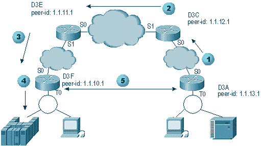
On the other hand, when you use border peers, that remote router needs to send only one request to the border peer. This request is then propagated through the groups, and the remote router opens a peer with the other remote router to start a circuit and establish a connection. This process is explained in this diagram:
-
When D3A receives the explorer, it sends a broadcast to D3C. D3C is the border peer to which D3A is attached.
-
When D3C receives the CUR frame, it sends the CUR frame to all the peers in the group. D3C also sends a test frame to any local interfaces that are configured to do so, and sends a CUR frame to the border peers in the other group.
-
D3E receives the CUR from D3C in another group. Then D3E does the same by sending the CUR to all the peers in the group and any local interfaces.
-
D3F receives the CUR frame and sends a test poll to the local interface. If D3F has a peer pointing to another router, it cannot echo that CUR frame to another router.
-
When the D3F receives a reply for the end station, it returns the Icanreach frame to D3E.
-
D3E sends it to D3C, which forwards it to D3A. D3A sends a test response to the device.
-
When the end station starts a dlsw circuit, with XID for SNA and SABME for NetBIOS, D3A initiates a peer connection with D3F and starts up the session.
This is the debug from both D3C and D3A during this process:
d3a#
DLSW Received-ctlQ : CLSI Msg : TEST_STN.Ind   dlen: 40
CSM: Received CLSI Msg : TEST_STN.Ind   dlen: 40 from TokenRing0
CSM:   smac c001.68ff.0000, dmac 4000.0000.0001, ssap 4 , dsap 0
DLSw: sending bcast to BP peer 1.1.12.1(2065)
The test frame that comes into the router is seen. Then, the router generates a CUR frame to D3C. D3C activity displays this output:
DLSw: Pak from peer 1.1.13.1(2065) with op DLX_MEMBER_TO_BP
DLSw: recv_member_to_border() from peer 1.1.13.1(2065)
DLSw: passing pak to core originally from 1.1.13.1 in group 2
%DLSWC-3-RECVSSP: SSP OP = 3( CUR  ) -explorer from peer 1.1.13.1(2065)
DLSw: Pak from peer 1.1.11.1(2065) with op DLX_RELAY_RSP
DLSW: relaying pak to member 1.1.13.1 in group 2
When D3C receives the packet from D3A, it forwards the packet to the core. Later, you see the response from the remote peer that is being relayed back to D3A. Then D3A starts up the connection (peer on demand) with the remote peer D3F in this debug:
DLSw: Pak from peer 1.1.12.1(2065) with op DLX_RELAY_RSP
DLSW: creating a peer-on-demand for 1.1.10.1
DLSw: passing pak to core originally from 1.1.10.1 in group 1
%DLSWC-3-RECVSSP: SSP OP = 4( ICR  ) -explorer from peer 1.1.10.1(2065)
DISP Sent : CLSI Msg : TEST_STN.Rsp   dlen: 44
DLSW Received-ctlQ : CLSI Msg : ID_STN.Ind   dlen: 54
CSM: Received CLSI Msg : ID_STN.Ind   dlen: 54 from TokenRing0
CSM:   smac c001.68ff.0000, dmac 4000.0000.0001, ssap 4 , dsap 4
DLSw: new_ckt_from_clsi(): TokenRing0 4001.68ff.0000:4->4000.0000.0001:4
DLSw: action_a() attempting to connect peer 1.1.10.1(2065)
DLSw: action_a(): Write pipe opened for peer 1.1.10.1(2065)
DLSw: peer 1.1.10.1(2065), old state DISCONN, new state WAIT_RD
DLSw: passive open 1.1.10.1(11003) -> 2065
DLSw: action_c(): for peer 1.1.10.1(2065)
DLSw: peer 1.1.10.1(2065), old state WAIT_RD, new state CAP_EXG
DLSw: CapExId Msg sent to peer 1.1.10.1(2065)
DLSw: Recv CapExId Msg from peer 1.1.10.1(2065)
DLSw: Pos CapExResp sent to peer 1.1.10.1(2065)
DLSw: action_e(): for peer 1.1.10.1(2065)
DLSw: Recv CapExPosRsp Msg from peer 1.1.10.1(2065)
DLSw: action_e(): for peer 1.1.10.1(2065)
DLSw: peer 1.1.10.1(2065), old state CAP_EXG, new state CONNECT
DLSw: peer_act_on_capabilities() for peer 1.1.10.1(2065)
DLSw: action_f(): for peer 1.1.10.1(2065)
DLSw: closing read pipe tcp connection for peer 1.1.10.1(2065)
DLSw: new_ckt_from_clsi(): TokenRing0 4001.68ff.0000:4->4000.0000.0001:4
DLSw: START-FSM (1474380): event:DLC-Id state:DISCONNECTED
DLSw: core: dlsw_action_a()
DISP Sent : CLSI Msg : REQ_OPNSTN.Req   dlen: 106
DLSw: END-FSM (1474380): state:DISCONNECTED->LOCAL_RESOLVE
After the router receives the relayed packet from the border peer, it opens a peer on demand with the remote peer D3F (1.1.10.1), and starts up the circuit.
debugging
The first step in any DLSw network is bringing up the peers. Without the peers, there is no exchange of data. Most of the details of what occurs between DLSw peers is explained in RFC 1795.
Note: If you talk to non-Cisco equipment via DLSw, use DLSw. However, between Cisco routers, use DLSw+.
This output is from issuing debug dlsw peers and bringing up the peers up between two Cisco routers:
DLSw: passive open 5.5.5.1(11010) -> 2065
DLSw: action_b(): opening write pipe for peer 5.5.5.1(2065)
DLSw: peer 5.5.5.1(2065), old state DISCONN, new state CAP_EXG
DLSw: CapExId Msg sent to peer 5.5.5.1(2065)
DLSw: Recv CapExId Msg from peer 5.5.5.1(2065)
DLSw: Pos CapExResp sent to peer 5.5.5.1(2065)
DLSw: action_e(): for peer 5.5.5.1(2065)
DLSw: Recv CapExPosRsp Msg from peer 5.5.5.1(2065)
DLSw: action_e(): for peer 5.5.5.1(2065)
shSw: peer 5.5.5.1(2065), old state CAP_EXG, new state CONNECT
DLSw: peer_act_on_capabilities() for peer 5.5.5.1(2065)
DLSw: action_f(): for peer 5.5.5.1(2065)
DLSw: closing read pipe tcp connection for peer 5.5.5.1(2065)
This output shows the router starting up the peer and opening a TCP session with the other router. Then it starts to exchange capabilities. After positive exchange of capabilities, the peer is connected. In contrast to RSRB, DLSw does not move the peer to a closed state when there is no activity, such as traffic. They always remain connected. If the peers are disconnected, issue debug dlsw peer to determine why they are not capable of opening.
When troubleshooting a session being brought up, issue debug dlsw core to observe the session failure and to verify if the circuit is coming up.
This is the flow for a 3174 communications controller to the host via DLSw+:
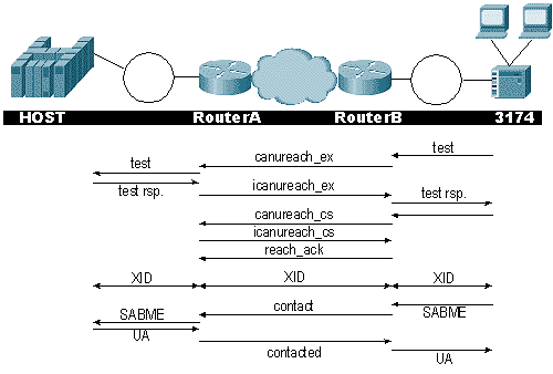
The debug dlsw output displays the flow of the session being brought up correctly:
ibu-7206#debug dlsw
DLSw reachability debugging is on at event level for all protocol traffic
DLSw peer debugging is on
DLSw local circuit debugging is on
DLSw core message debugging is on
DLSw core state debugging is on
DLSw core flow control debugging is on
DLSw core xid debugging is on
ibu-7206#
DLSW Received-ctlQ : CLSI Msg : UDATA_STN.Ind   dlen: 208
CSM: Received CLSI Msg : UDATA_STN.Ind   dlen: 208 from TokenRing3/0
CSM:   smac 8800.5a49.1e38, dmac c000.0000.0080, ssap F0, dsap F0
CSM: Received frame type NETBIOS DATAGRAM from 0800.5a49.1e38, To3/0
DLSw: peer_put_bcast() to non-grouped peer 5.5.5.1(2065)
DLSw: Keepalive Request sent to peer 5.5.5.1(2065))
DLSw: Keepalive Response from peer 5.5.5.1(2065)
DLSW Received-ctlQ : CLSI Msg : TEST_STN.Ind   dlen: 41
CSM: Received CLSI Msg : TEST_STN.Ind   dlen: 41 from TokenRing3/0
CSM:   smac c001.68ff.0001, dmac 4000.0000.0001, ssap 4 , dsap 0
Notice the test frame coming from the LAN (locally) from station c001.68ff.0001 to the MAC address of 4000.0000.0001. Each .Ind indicates that a packet is coming in from the LAN. When the router sends a packet to the LAN, you see a .RSP.
DLSw: peer_put_bcast() to non-grouped peer 5.5.5.1(2065)
%DLSWC-3-RECVSSP: SSP OP = 4( ICR  ) -explorer from peer 5.5.5.1(2065)
DISP Sent : CLSI Msg : TEST_STN.Rsp   dlen: 44
Now you can see the broadcast sent to the remote peer and the initial cell rate (ICR) response back. This means that the remote router identified the station as reachable. The TEST_STN.Rsp is the router sending a test response to the station.
DLSW Received-ctlQ : CLSI Msg : ID_STN.Ind   dlen: 54
CSM: Received CLSI Msg : ID_STN.Ind   dlen: 54 from TokenRing3/0
CSM:   smac c001.68ff.0001, dmac 4000.0000.0001, ssap 4 , dsap 4
After the station receives the test response, it sends the first XID. You can notice this with the IS_STN.Ind. Now the router has to hold onto this frame temporarily until it clears a couple of details in between the two DLSw routers.
DLSw: new_ckt_from_clsi(): TokenRing3/0 4001.68ff.0001:4->4000.0000.0001:4
DLSw: START-FSM (1622182940): event:DLC-Id state:DISCONNECTED
DLSw: core: dlsw_action_a()
DISP Sent : CLSI Msg : REQ_OPNSTN.Req   dlen: 108
DLSw: END-FSM (1622182940): state:DISCONNECTED->LOCAL_RESOLVE

DLSW Received-ctlQ : CLSI Msg : REQ_OPNSTN.Cfm CLS_OK dlen: 108
DLSw: START-FSM (1622182940): event:DLC-ReqOpnStn.Cnf state:LOCAL_RESOLVE
DLSw: core: dlsw_action_b()
CORE: Setting lf size to 30
%DLSWC-3-SENDSSP: SSP OP = 3(CUR)  to peer 5.5.5.1(2065) success
DLSw: END-FSM (1622182940): state:LOCAL_RESOLVE->CKT_START

%DLSWC-3-RECVSSP: SSP OP = 4(ICR)  from peer 5.5.5.1(2065)
DLSw: 1622182940 recv FCI 0 - s:0 so:0 r:0 ro:0
DLSw: recv RWO
DLSw: START-FSM (1622182940): event:WAN-ICR state:CKT_START
DLSw: core: dlsw_action_e()
DLSw: sent RWO
DLSw: 1622182940 sent FCI 80 on  ACK   - s:20 so:1 r:20 ro:1
%DLSWC-3-SENDSSP: SSP OP = 5(ACK)  to peer 5.5.5.1(2065) success
DLSw: END-FSM (1622182940): state:CKT_START->CKT_ESTABLISHED
Here you can notice the internal flow of DLSw between the two peers. These packets are normal for each session startup. The first stage is to move from a disconnected state to a CKT_ESTABLISHED state. Both routers transmit a CUR frame for the circuit itself. This is called can u reach circuit setup (CURCS). When the peer that initiates the CURCS frame receives an ICRCS frame, it sends an acknowledgment and moves to a circuit established state. Now, both DLSw routers are ready for XID processing.
DLSw: START-FSM (1622182940): event:DLC-Id state:CKT_ESTABLISHED
DLSw: core: dlsw_action_f()
DLSw: 1622182940 sent FCA on  XID
%DLSWC-3-SENDSSP: SSP OP = 7(XID)  to peer 5.5.5.1(2065) success
DLSw: END-FSM (1622182940): state:CKT_ESTABLISHED->CKT_ESTABLISHED
The router received an XID after sending the test response to the station. It saves this XID for a moment, then transmits it to the peer across the circuit. This means you are sending packets to/from the peer with the circuit ID tagged to them. This way, DLSw understands the activity between the two stations. Remember that DLSw terminates the Logical Link Control, type 2 (LLC2), session at each side of the cloud.
%DLSWC-3-RECVSSP: SSP OP = 7(XID)  from peer 5.5.5.1(2065)
DLSw: 1622182940 recv FCA on  XID   - s:20 so:0 r:20 ro:0
DLSw: START-FSM (1622182940): event:WAN-XID state:CKT_ESTABLISHED
DLSw: core: dlsw_action_g()
DISP Sent : CLSI Msg : ID.Rsp   dlen: 12
DLSw: END-FSM (1622182940): state:CKT_ESTABLISHED->CKT_ESTABLISHED

DLSW Received-ctlQ : CLSI Msg : ID.Ind   dlen: 39
DLSw: START-FSM (1622182940): event:DLC-Id state:CKT_ESTABLISHED
DLSw: core: dlsw_action_f()
%DLSWC-3-SENDSSP: SSP OP = 7(XID)  to peer 5.5.5.1(2065) success
DLSw: END-FSM (1622182940): state:CKT_ESTABLISHED->CKT_ESTABLISHED
You first notice a response to the first XID that was sent before. In ID.Rsp, you see that the XID was sent to the station, to which the station responded with an ID.Ind. This is another XID that was sent across to the DLSw peer.
%DLSWC-3-RECVSSP: SSP OP = 8(CONQ)  from peer 5.5.5.1(2065)
DLSw: START-FSM (1622182940): event:WAN-CONQ state:CKT_ESTABLISHED
This part shows us that the station on the other side responded with a SABME (CONQ) to the XID. The XID negotiation has terminated and the router is ready to start the session.
DLSw: core: dlsw_action_i()
DISP Sent : CLSI Msg : CONNECT.Req   dlen: 16
Next, the router sends the SABME to the station in CONNECT.Req.
DLSw: END-FSM (1622182940): state:CKT_ESTABLISHED->CONTACT_PENDING

DLSW Received-ctlQ : CLSI Msg : CONNECT.Cfm CLS_OK dlen: 8
DLSw: START-FSM (1622182940): event:DLC-Connect.Cnf state:CONTACT_PENDING
DLSw: core: dlsw_action_j()
%DLSWC-3-SENDSSP: SSP OP = 9( CONR )  to peer 5.5.5.1(2065) success
DISP Sent : CLSI Msg : FLOW.Req   dlen: 0
DLSw: END-FSM (1622182940): state:CONTACT_PENDING->CONNECTED
Then you receive the unnumbered acknowledgement (UA) from the station, which is shown in the CONNECT.Cfm message. This is sent to the remote peer via a CONR. Then the relative rate (RR) process is started with FLOW.Req.
%DLSWC-3-RECVSSP: SSP OP = 10(INFO)  from peer 5.5.5.1(2065)
DLSw: 1622182940 decr r - s:20 so:0 r:19 ro:0
DLSw: START-FSM (1622182940): event:WAN-INFO state:CONNECTED
DLSw: core: dlsw_action_m()
DISP Sent : CLSI Msg : DATA.Req   dlen: 34
DLSw: END-FSM (1622182940): state:CONNECTED->CONNECTED

DLSw: 1622182940 decr s - s:19 so:0 r:19 ro:0
DLSW Received-disp : CLSI Msg : DATA.Ind   dlen: 35
DLSw: sent RWO
DLSw: 1622182940 sent FCI 80 on  INFO  - s:19 so:0 r:39 ro:1
%DLSWC-3-SENDSSP: SSP OP = 10(INFO)  to peer 5.5.5.1(2065) success
%DLSWC-3-RECVSSP: SSP OP = 10(INFO)  from peer 5.5.5.1(2065)
DLSw: 1622182940 decr r - s:19 so:0 r:38 ro:1
DLSw: 1622182940 recv FCA on  INFO  - s:19 so:0 r:38 ro:0
DLSw: 1622182940 recv FCI 0 - s:19 so:0 r:38 ro:0
DLSw: recv RWO
DLSw: START-FSM (1622182940): event:WAN-INFO state:CONNECTED
DLSw: core: dlsw_action_m()
DISP Sent : CLSI Msg : DATA.Req   dlen: 28
DLSw: END-FSM (1622182940): state:CONNECTED->CONNECTED
The DATA.Req indicates that the router transmitted an I-frame. Data.Ind indicates that the router received an I-frame. You can use this information to determine packet flow across the DLSw routers.
DLSW Received-ctlQ : CLSI Msg : DISCONNECT.Ind   dlen: 8
DLSw: START-FSM (1622182940): event:DLC-Disc.Ind state:CONNECTED
This part contains a DISCONNECT.Ind. An .Ind indicates a packet coming in from the LAN. In this case, the station sends a DISCONNECT, which causes the router to start tearing down the circuit.
DLSw: core: dlsw_action_n()
%DLSWC-3-SENDSSP: SSP OP = 14( HLTQ )  to peer 5.5.5.1(2065) success
DLSw: END-FSM (1622182940): state:CONNECTED->DISC_PENDING

%DLSWC-3-RECVSSP: SSP OP = 15( HLTR )  from peer 5.5.5.1(2065)
DLSw: START-FSM (1622182940): event:WAN-HLTR state:DISC_PENDING
After the router receives the DISCONNECT, it sends a HALT to the remote peer and waits for the response. All that is left is to send a UA to the station and close down the circuit, which is shown in the following debug with the DISCONNECT.Rsp:
DLSw: core: dlsw_action_q()
DISP Sent : CLSI Msg : DISCONNECT.Rsp   dlen: 4
DISP Sent : CLSI Msg : CLOSE_STN.Req   dlen: 4
DLSw: END-FSM (1622182940): state:DISC_PENDING->CLOSE_PEND

DLSW Received-ctlQ : CLSI Msg : CLOSE_STN.Cfm CLS_OK dlen: 8
DLSw: START-FSM (1622182940): event:DLC-CloseStn.Cnf state:CLOSE_PEND
DLSw: core: dlsw_action_y()
DLSw: 1622182940 to dead queue
DLSw: END-FSM (1622182940): state:CLOSE_PEND->DISCONNECTED
The last thing DLSw performs is to put the circuit in the dead queue. From there, pointers are cleaned up and ready for a new circuit.
NetBIOS Sessions
DLSw handles NetBIOS sessions differently, but the debugs are very similar.
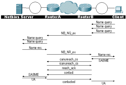
Note: Remember that XIDs do not flow for NetBIOS stations and that the DLSw routers exchange NetBIOS name query system switch processor (SSP) frames and NetBIOS name recognized. This is the main difference.
 Feedback