Understanding VPDN
Available Languages
Contents
Introduction
A virtual private dial-up network (VPDN) allows a private network dial in service to span across to remote access servers (defined as the L2TP Access Concentrator [LAC]).
When a Point-to-Point Protocol (PPP) client dials into a LAC, the LAC determines that it should forward that PPP session on to an L2TP Network Server (LNS) for that client. The LNS then authenticates the user and starts the PPP negotiation. Once PPP setup has completed, all frames are sent through the LAC to the client and the LNS.
Prerequisites
Requirements
There are no specific requirements for this document.
Components Used
This document is not restricted to specific software and hardware versions.
The information presented in this document was created from devices in a specific lab environment. All of the devices used in this document started with a cleared (default) configuration. If you are working in a live network, ensure that you understand the potential impact of any command before using it.
Conventions
For more information on document conventions, refer to the Cisco Technical Tips Conventions.
Glossary
-
Client: PC or router attached to a remote access network, which is the initiator of a call.
-
L2TP: Layer 2 Tunnel Protocol. PPP defines an encapsulation mechanism for transporting multiprotocol packets across layer 2 (L2) point-to-point links. Typically, a user obtains an L2 connection to a Network Access Server (NAS) using a technique such as dialup plain old telephone service (POTS), ISDN or Asymmetric Digital Subscriber Line (ADSL). The user then runs PPP over that connection. In such a configuration, the L2 termination point and PPP session endpoint reside on the same physical device (the NAS).
L2TP extends the PPP model by allowing the L2 and PPP endpoints to reside on different devices interconnected by a network. With L2TP, the user has an L2 connection to an access concentrator, and the concentrator then tunnels individual PPP frames to the NAS. This allows the actual processing of PPP packets to be divorced from the termination of the L2 circuit.
-
L2F: Layer 2 Forwarding Protocol. L2F is a tunneling protocol older than L2TP.
-
LAC: L2TP Access Concentrator. A node that acts as one side of an L2TP tunnel endpoint and is a peer to the LNS. The LAC sits between an LNS and a client and forwards packets to and from each. Packets sent from the LAC to the LNS require tunneling with the L2TP protocol. The connection from the LAC to the client is typically through ISDN or analog.
-
LNS: L2TP Network Server. A node that acts as one side of an L2TP tunnel endpoint and is a peer to the LAC. The LNS is the logical termination point of a PPP session that is being tunneled from the client by the LAC.
-
Home Gateway: Same definition as LNS in L2F terminology.
-
NAS: Same definition as LAC in L2F terminology.
-
Tunnel: In L2TP terminology, a tunnel exists between a LAC-LNS pair. The tunnel consists of a control connection and zero or more L2TP Sessions. The tunnel carries encapsulated PPP datagrams and control messages between the LAC and the LNS. The process is the same for L2F.
-
Session: L2TP is connection-oriented. The LNS and LAC maintain a state for each call that is initiated or answered by an LAC. An L2TP session is created between the LAC and LNS when an end-to-end PPP connection is established between a client and the LNS. Datagrams related to the PPP connection are sent over the tunnel between the LAC and LNS. There is a one-to-one relationship between established L2TP sessions and their associated calls. The process is the same for L2F.
Overview of the VPDN Process
In the description of the VPDN process below, we use the L2TP terminology (LAC and LNS).

-
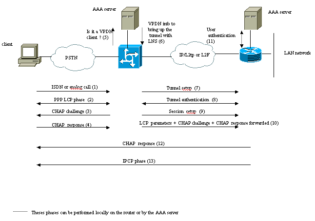
The client calls the LAC (typically using a modem or an ISDN card).
-
The client and the LAC starts the PPP phase by negotiating the LCP options (authentication method Password Authentication Protocol [PAP] or Challenge Handshake Authentication Protocol [CHAP], PPP multilink, compression, and so on).
-
Let's suppose that CHAP has been negotiated in step 2. The LAC sends a CHAP challenge to the client.
-
The LAC gets a response (for instance username@DomainName and password).
-
Based on the domain name received in the CHAP response or the Dialed Number Information Service (DNIS) received in the ISDN setup message, the LAC checks whether the client is a VPDN user. It does this by using its local VPDN configuration or contacting an Authentication, Authorization, and Accounting (AAA) server.
-
Because the client is a VPDN user, the LAC gets some information (from its local VPDN configuration or from an AAA server) that it uses to bring up a L2TP or L2F tunnel with the LNS.
-
The LAC brings up a L2TP or L2F tunnel with the LNS.
-
Based on the name received in the request from the LAC, the LNS checks if the LAC is allowed to open a tunnel (the LNS checks its local VPDN configuration). Moreover, the LAC and the LNS authenticate each other (they use their local database or contact an AAA server). The Tunnel is then up between both devices. In this tunnel, several VPDN sessions can be carried.
-
For the client username@DomainName, a VPDN session is triggered from the LAC to the LNS. There is one VPDN session per client.
-
The LAC forwards the LCP options it has negotiated to the LNS with the client along with the username@DomainName and password received from the client.
-
The LNS clones a virtual-access from a virtual-template specified in the VPDN configuration. The LNS takes the LCP options received from the LAC and authenticate the client locally or by contacting the AAA server.
-
The LNS sends a CHAP response to the client.
-
The IP Control Protocol (IPCP) phase is performed and then the route is installed: the PPP session is up and running between the client and the LNS. The LAC just forwards the PPP frames. The PPP frames are tunneled between the LAC and the LNS.
Tunneling Protocols
A VPDN tunnel can be built using either Layer-2 Forwarding (L2F) or Layer-2 Tunneling Protocol (L2TP).
-
L2F was introduced by Cisco in Request For Comments (RFC) 2341 and is also used to forward PPP sessions for Multichassis Multilink PPP.
-
L2TP, introduced in RFC 2661, combines the best of the Cisco L2F protocol and Microsoft Point-to-Point Tunneling Protocol (PPTP). Moreover, L2F supports only dial-in VPDN while L2TP supports both dial-in and dial-out VPDN.
Both protocols use the UDP port 1701 to build a tunnel through an IP network to forward link-layer frames. For L2TP, the setup for tunneling a PPP session consists of two steps:
-
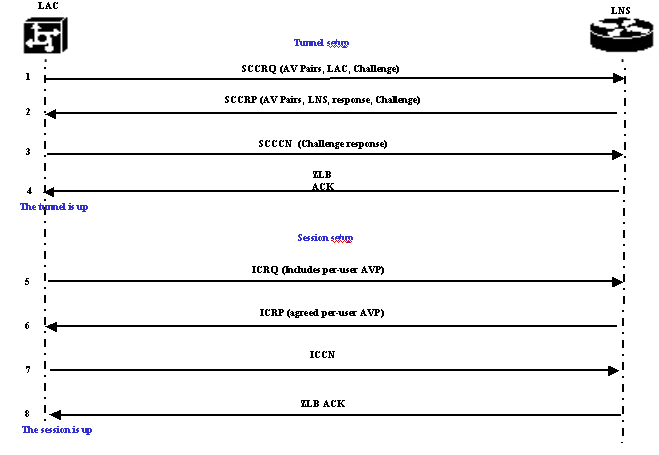
Establishing a tunnel between the LAC and the LNS. This phase takes place only when there is no active tunnel between both devices.
-
Establishing a session between the LAC and the LNS.

The LAC decides that a tunnel must be initiated from the LAC to the LNS.
-
The LAC sends a Start-Control-Connection-Request (SCCRQ). A CHAP challenge and AV Pairs are included in this message.
-
The LNS responds with a Start-Control-Connection-Reply (SCCRP). A CHAP challenge, the response to LAC's challenge and AV Pairs are included in this message.
-
The LAC sends a Start-Control-Connection-Connected (SCCCN). The CHAP response is included in this message.
-
The LNS responds with a Zero-Length Body Acknowledgement (ZLB ACK). That acknowledgement may be carried in another message. The tunnel is up.
-
The LAC sends an Incoming-Call-Request (ICRQ) to the LNS.
-
The LNS responds with an Incoming-Call-Reply (ICRP) message.
-
The LAC sends an Incoming-Call-Connected (ICCN).
-
The LNS responds back with a ZLB ACK. That acknowledgement may also be carried in another message.
-
The session is up.
Note: The messages above used for opening a tunnel or a session carry Attribute Value Pairs (AVPs) defined in RFC 2661. They describe properties and information (such as Bearercap, hostname, vendor name and window size). Some AV pairs are mandatory and others are optional.
Note: A Tunnel ID is used to multiplex and demultiplex tunnels between the LAC and LNS. A session ID is used to identify a particular session with the tunnel.
For L2F, the setup for tunneling a PPP session is the same as for L2TP. It involves:
-
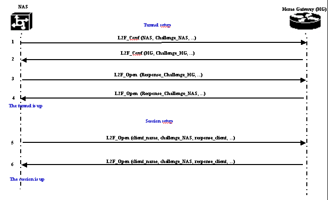
Establishing a tunnel between the NAS and the Home Gateway. This phase takes place only when there is no active tunnel between both devices.
-
Establishing a session between the NAS and the Home Gateway.

The NAS decides that a tunnel must be initiated from the NAS to the Home Gateway.
-
The NAS sends a L2F_Conf to Home Gateway. A CHAP challenge is included in this message.
-
The Home Gateway responds with a L2F_Conf. A CHAP challenge is included in this message.
-
The NAS sends a L2F_Open. The CHAP response of the Home Gateway challenge is included in this message.
-
The Home Gateway responds with a L2F_Open. The CHAP response of the NAS challenge is included in this message. The tunnel is up.
-
The NAS sends a L2F_Open to the Home Gateway. The packet includes the username of the client (client_name), the CHAP challenge sent by the NAS to the client (challenge_NAS) and its response (response_client).
-
The Home Gateway, by sending back the L2F_OPEN, accepts the client. Traffic is now free to flow in either direction between the client and the Home Gateway.
Note: A tunnel is identified with a CLID (Client ID). Multiplex ID (MID) identifies a particular connection within the tunnel.
Configuring VPDN
For information on configuring VPDN, refer to the Configuring Virtual Private Networks manual, and go to the section on Configuring VPN.
Related Information
Contact Cisco
- Open a Support Case

- (Requires a Cisco Service Contract)
 Feedback