Identify AS5xxx Platform Controllers and Modem Hardware
Available Languages
Contents
Introduction
The purpose of this document is to provide a quick reference to identifying the different kinds of controllers and internal modems for these access servers:
-
AS5200
-
AS5300
-
AS5350
-
AS5400
-
AS5800
-
AS5850
Prerequisites
Requirements
There are no specific requirements for this document.
Components Used
This document is not restricted to specific software and hardware versions.
Conventions
For more information on document conventions, refer to the Cisco Technical Tips Conventions.
AS5200
To help identify the modem and carrier card you have, you need to look at the rear panel of the AS5200.
Figure 1 – Cisco AS5200 Rear Panel 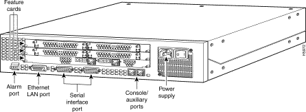


Internal Modems
The AS5200 access server supports these internal modem modules:
Figure 5 – MCOM V.34 12-Port Module (AS52-12-M-V34) 


Determine the Type of Internal MCOM Modem (V.90 or V.34)
Issue the show modem version command to list all modem code files in the boot Flash memory and system Flash memory, as well as the modem code files bundled with Cisco IOS Software. You can also determine if the hardware of the MCOM modems supports V.90 or V.34 modems. Within the show modem version command output, look for the section Modem board HW version info:. The vendor_banner= output indicates whether the MCOM modems are V.90 or V.34. If you have V.34 modems, your AS5200 does not support speeds above 33.6kbps (V.34).
Sample Output: V.34 (V.34 12-Port Module)
5200#show modem version
                Modem module     Firmware   Boot          DSP
  Mdm           Number           Rev        Rev           Rev
  1/0               0            1.0(23)    1.0(5)
  1/1               0            1.0(23)    1.0(5)
  1/2               0            1.0(23)    1.0(5)
  1/3               0            1.0(23)    1.0(5)

!--- Output suppressed.


  2/22             1             1.0(23)    1.0(5)
  2/23             1             1.0(23)    1.0(5)
 Modem board HW version info:
Slot 1:
   Carrier card:
     hw version= 8, number_of_ports= 24, max_modules= 2, max_oob_ports= 2
   Modem Module 0:
     number_of_modems= 12, option_bits= 1,
     rev_num= 03.00, vendor_model_number= 01,
     vendor_banner= Microcom MNP10 V34 Modem

!--- This indicates that the MCOM modems are only V.34 capable.
Sample Output: V.90 (56K 12-Port Module)
5200#show modem version
                Modem module      Firmware        Boot          DSP
  Mdm           Number            Rev             Rev           Rev
  1/0               0             5.0(40)         3.0(4)        22.0/47.0
  1/1               0             5.0(40)         3.0(4)        22.0/47.0

!--- Output suppressed.


  1/22              1             5.0(40)         3.0(4)       22.0/47.0
  1/23              1             5.0(40)         3.0(4)       22.0/47.0
Modem board HW version info:
Slot 1:
   Carrier card:
     hw version= 8, pld= 0, number_of_ports= 24,
     max_modules= 2, max_oob_ports= 2
   Modem Module 0:
     number_of_modems= 12, option_bits= 1,
     rev_num= 03.00, vendor_model_number= 02,
     vendor_banner= Microcom MNP10 K56 Modem

!--- This indicates that the MCOM modems are V.90 (56K) capable.
Display Modem Code Versions
Issue the show modem mapping command to list all modem code files in the boot Flash memory and system Flash memory, as well as the modem code files bundled with Cisco IOS Software.
5200#show modem mapping
Slot 1 has Microcom Carrier card.

!--- Slot 1 on this router is an MCOM modem card.

      Module  Firmware     Firmware
Mdm   Number  Rev          Filename
1/0      0    5.3(30)      IOS-Default

!--- Modems 1/0 through 1/23 have MCOM Portware 5.3(30) loaded on them. !--- This firmware is bundled with Cisco IOS Software.

1/1      0    5.3(30)      IOS-Default
1/2      0    5.3(30)      IOS-Default
1/3      0    5.3(30)      IOS-Default
1/4      0    5.3(30)      IOS-Default

!--- Output suppressed.


1/21     1    5.3(30)      IOS-Default
1/22     1    5.3(30)      IOS-Default
1/23     1    5.3(30)      IOS-Default
Firmware-file                                     Version  Firmware-Type
=============                                     =======  =============
system:/ucode/mica_board_firmware                 2.0.2.0  Mica Boardware
system:/ucode/mica_port_firmware                  2.7.3.0  Mica Portware
system:/ucode/microcom_firmware                   5.3.30   Microcom F/W and DSP
bootflash:mcom-modem-code.5.3.30.bin              5.3.30   Microcom F/W and DSP

!--- The various modem codes available to the AS5200. Cisco IOS Software has both !--- Modem ISDN Channel Aggregation (MICA) and MCOM firmware bundled, even though !--- only MCOM hardware is used in this example. Issue the firmware location command !--- to use a different firmware.
Figure 8 – MICA Carrier Card (AS52-CC-DM) with Six-Port MICA Modules (AS52-6DM)


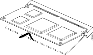
The MICA modems are located on the carrier card. There are six modems per 6DM.
-
MICA carrier card with 24 ports: AS52-24DM-CC=
-
MICA carrier card with 30 ports: AS52-30DM-CC=
-
Six-port MICA modules: 6DM=
Identify the Internal MICA Carrier Card Through Cisco IOS Software
Issue the show modem version command to list all modem code files in the boot Flash memory and system Flash memory, as well as the modem code files bundled with Cisco IOS Software. You can also determine which carrier card is present in the Modem board HW version info: section of the show modem version command output by looking at the carrier card info, which contains the information on the carrier cards.
MICA Modems V.90
Issue the show modem version command to determine the capacity of the carrier cars. Unlike on MCOM modems, the show modem version command on MICA modems does not display vendor_banner= information.
5200#show modem version
  Codes:
  d - DSP software download is required for achieving K56flex connections
                Modem module     Firmware    Boot          DSP
  Mdm           Number            Rev        Rev           Rev
  1/0               0            2.7.2.1
  1/1               0            2.7.2.1

!--- Output suppressed.


  1/22              3            2.7.2.1
  1/23              3            2.7.2.1

Modem board HW version info:

Slot 1:
Carrier card:
     number_of_ports= 30, max_modules= 5

!--- The maximum number of ports will be either 24 or 30.

Manufacture Cookie is not programmed.
Modem Module 0
Manufacture Cookie Info:
 EEPROM Type 0x0101, EEPROM Version 0x01, Board ID 0x06,
 Board Hardware Version 1.0, Item Number 73-2522-3,
 Board Revision A48, Serial Number 08559417,
 PLD/ISP Version 255.255, Manufacture Date 21-Oct-1998.

!--- Output suppressed.
Display Modem Code Versions
Issue the show modem mapping command to list all modem code files in the boot Flash memory and system Flash memory, as well as the modem code files bundled with Cisco IOS Software. The command also allows you to determine which internal modems you have through Cisco IOS Software.
5200#show modem mapping
Slot 1 has Mica Carrier card.

!--- Slot 1 on this router is a MICA modem card.

        Modem      Firmware   Firmware
Module  Numbers    Rev        Filename
  0   1/0  - 1/5     2.7.3.0    flash:mica-modem-pw.2.7.3.0.bin

!--- Modems 1/0 through 1/47 have MICA portware 2.7.3.0 loaded on to them. !--- This firmware is bundled with Cisco IOS Software.

  1   1/6  - 1/11   2.7.3.0   flash:mica-modem-pw.2.7.3.0.bin
  2   1/12 - 1/17  2.7.3.0    flash:mica-modem-pw.2.7.3.0.bin
  3   1/18 - 1/23  2.7.3.0    flash:mica-modem-pw.2.7.3.0.bin
  4   1/24 - 1/29  2.7.3.0    flash:mica-modem-pw.2.7.3.0.bin
  5   1/30 - 1/35  2.7.3.0    flash:mica-modem-pw.2.7.3.0.bin
  6   1/36 - 1/41  2.7.3.0    flash:mica-modem-pw.2.7.3.0.bin
  7   1/42 - 1/47  2.7.3.0    flash:mica-modem-pw.2.7.3.0.bin
Firmware-file                                     Version  Firmware-Type
=============                                     =======  =============
system:/ucode/mica_board_firmware                 2.0.2.0  Mica Boardware
system:/ucode/mica_port_firmware                  2.7.3.0  Mica Portware
system:/ucode/microcom_firmware                   5.3.30   Microcom F/W and DSP
flash:mica-modem-pw.2.7.3.0.bin                   2.7.3.0  Mica Portware

!--- The various modem codes available to the AS5200. Cisco IOS Software has both MICA and MCOM !--- firmware bundled, even though only MICA hardware is used. !--- Issue the firmware location command to use a different firmware.
AS5300
To help identify the T1/E1, modem, and carrier cards you have, you need to look at the rear panel of the AS5300.
Figure 11 – Cisco AS5300 Rear Panel 

The Quad T1/PRI card without serial interfaces includes four RJ-45 ports (for the T1 connection).
Figure 13 – Quad E1/PRI Card Without Serial Interfaces (AS53-4CE1) 
The Quad E1/PRI WAN card without serial interfaces includes four RJ-45 ports for terminating 120-ohm balanced lines or 75-ohm unbalanced lines.
Figure 14 – Quad T1/PRI or E1/PRI Card with Serial Interfaces (AS53-4CT1+ /AS53-4CE1+) 
The Quad T1/PRI and Quad E1/PRI cards with serial interfaces. The board provides four RJ-45 T1 or E1 PRI ports and four serial interfaces for backhaul WAN support.
Note: These cards do not support MCOM modems.
Figure 15 – Octal T1/PRI and E1/PRI Cards (AS53-8CT1+ /AS53-8CE1+) 
Octal T1/PRI and E1/PRI cards provide eight RJ-45 T1 or E1 PRI ports and four serial interfaces for backhaul WAN support.
Note: These cards do not support MCOM modems.
Internal Modems
The AS5300 access server supports both MICA and MCOM modems.
Figure 16 – MCOM Carrier Card (AS53-MCC) 


The 12-port modules are located in the MCOM carrier card. The 12-port modules cannot be used as stand-alone cards and they cannot be installed in MICA carrier cards.
Determine the Type of Internal MCOM Modems (V.90 or V.34)
Issue the show modem version command to list all modem code files in the boot Flash memory and system Flash memory, as well as the modem code files bundled with Cisco IOS Software. You can also determine which carrier card is present in the Modem board HW version info: section of the show modem version command output by looking at the carrier card info, which contains the information on the carrier cards.
Sample Output: V.34 (V.34 12-Port Module)
5300#show modem version
                Modem module     Firmware   Boot          DSP
  Mdm           Number           Rev        Rev           Rev
  1/0               0            1.0(23)       1.0(5)
  1/1               0            1.0(23)       1.0(5)
  1/2               0            1.0(23)       1.0(5)
  1/3               0            1.0(23)       1.0(5)

!--- Output suppressed.


  2/22             1             1.0(23)       1.0(5)
  2/23             1             1.0(23)       1.0(5)

Modem board HW version info:

Slot 1:
   Carrier card:
     hw version= 8, number_of_ports= 24, max_modules= 2, max_oob_ports= 2
   Modem Module 0:
     number_of_modems= 12, option_bits= 1,
     rev_num= 03.00, vendor_model_number= 01,
     vendor_banner= Microcom MNP10 V34 Modem

!--- This indicates that the MCOM modems are V.34 capable.
Sample Output: V.90 (56K 12-Port Module)
5300#show modem version
                Modem module     Firmware   Boot          DSP
  Mdm           Number           Rev        Rev           Rev
  1/0               0           5.0(40)     3.0(4)        22.0/47.0
  1/1               0           5.0(40)     3.0(4)        22.0/47.0

!--- Output suppressed.


  1/22              1           5.0(40)     3.0(4)        22.0/47.0
  1/23              1           5.0(40)     3.0(4)        22.0/47.0
Modem board HW version info:
Slot 1:
   Carrier card:
     hw version= 8, pld= 0, number_of_ports= 24,
     max_modules= 2, max_oob_ports= 2
   Modem Module 0:
     number_of_modems= 12, option_bits= 1,
     rev_num= 03.00, vendor_model_number= 02,
     vendor_banner= Microcom MNP10 K56 Modem

!--- This indicates that the MCOM modems are V.90 (56K) capable.
Display Modem Code Versions
Issue the show modem mapping command to list all modem code files in the boot Flash memory and system Flash memory, as well as the modem code files bundled with Cisco IOS Software.The command also allows you to determine which internal modems you have through Cisco IOS Software.
5300#show modem mapping
Slot 1 has Microcom Carrier card.
      Module  Firmware     Firmware
Mdm   Number  Rev          Filename
1/0      0    5.3(30)      IOS-Default

!--- Modem 1/0 has MCOM portware 5.3(30) loaded on it.

1/1      0    5.3(30)      IOS-Default
1/2      0    5.3(30)      IOS-Default
1/3      0    5.3(30)      IOS-Default

!--- Output suppressed.


1/21     1    5.3(30)      IOS-Default
1/22     1    5.3(30)      IOS-Default
1/23     1    5.3(30)      IOS-Default
Firmware-file                                     Version  Firmware-Type
=============                                     =======  =============
system:/ucode/mica_board_firmware                 2.0.2.0  Mica Boardware
system:/ucode/mica_port_firmware                  2.7.3.0  Mica Portware
system:/ucode/microcom_firmware                   5.3.30   Microcom F/W and DSP
bootflash:mcom-modem-code.5.3.30.bin              5.3.30   Microcom F/W and DSP

!--- These are the various modem codes available to the AS5300. Cisco IOS Software has both MICA and MCOM !--- firmware bundled, even though only MICA hardware is used. !--- Issue the firmware location command to use a different firmware.
MICA Carrier Cards
The MICA carrier card includes 10 slots in which you can install six- or 12-port modem modules. Therefore, in a fully populated carrier card you can have either 60 modems (if using the six-port modules) or 120 modems (if using the 12-port modules).
Note: Since there are two carrier card slots, a fully populated chassis can have 120 (if using the six-port modules) or 240 (if using the 12-port modules) modems per chassis.
Figure 19 – MICA Carrier Card (AS53-MCC=) 
Note: CC supports only single density MICA modems (6DM).
Figure 20 – MICA Carrier Card (AS53-CC2-DM=) 
Note: CC2 supports both double and single density modems (12DMs and 6DMs).
Identify the Internal MICA Carrier Card Through Cisco IOS Software
Issue the show modem version command to list all modem code files in the boot Flash memory and system Flash memory, as well as the modem code files bundled with Cisco IOS Software. You can also determine which carrier card is present in the Modem board HW version info: section of the show modem version command output by looking at the carrier card info, which contains the information on the carrier cards.
show modem version command output for a CC:
5300#show modem version

  Codes:
  d - DSP software download is required for achieving K56flex connections

                Modem module     Firmware   Boot          DSP
  Mdm           Number           Rev        Rev           Rev
  1/0               0            2.7.2.1
  1/1               0            2.7.2.1

!--- Output suppressed.


  1/22              3            2.7.2.1
  1/23              3            2.7.2.1
Modem board HW version info:

   Carrier card:
        number_of_ports= 48, max_modules= 10
   Manufacture Cookie Info:
    EEPROM Type 0x0001, EEPROM Version 0x01, Board ID 0x47,

 !--- Board ID 0x47 indicates the carrier card is CC. !--- This carrier card can accept only !--- Hex Modem Modules (HMMs) (six-port modules).

    Board Hardware Version 1.0, Item Number 73-2393-3,
    Board Revision A0, Serial Number 06466432,
    PLD/ISP Version 5.9, Manufacture Date 3-Nov-1997
show modem version command output for a CC2:
5300#show modem version

  Codes:
  d - DSP software download is required for achieving K56flex connections

                Modem module     Firmware   Boot          DSP
  Mdm     Number                  Rev            Rev           Rev
  1/0               0             2.7.2.1
  1/1               0             2.7.2.1

!--- Output suppressed.


  1/22              3            2.7.2.1
  1/23              3            2.7.2.1
Modem board HW version info:

   Slot 1:
   Carrier card:
        number_of_ports= 60, max_modules= 10
   Manufacture Cookie Info:
    EEPROM Type 0x0001, EEPROM Version 0x01, Board ID 0x4C,

 !--- Board ID 0x4C indicates the carrier card is CC2. !--- This carrier card can accept both HMMs and !--- Double-Density Modem Modules (DMMs).
    Board Hardware Version 1.0, Item Number 800-3680-1,
    Board Revision A0, Serial Number 20234639,
    PLD/ISP Version 2.2, Manufacture Date 10-May-2000.
MICA Carrier Card (AS53-MCC=) with 6-Port Modem Modules (6DM)
Figure 21 

Each six-port module includes six modems. The 6DM modems are also know as HMMs. In a fully populated MICA card, you can have up to 60 modems. In a fully populated access server chassis, you can have up to 120 modems. Ten of these modem modules can be configured on each of two cards for a total of 60 ports per card or a total of 120 ports per chassis.
MICA Carrier Card (AS53-CC2-DM=) with 12-Port Modem Modules (12DMM)
Figure 23 

Each 12-port module includes 12 modems. The 12-port MICA module is also known as a DMM. In a fully populated MICA card, you can have up to 120 ports. In a fully populated access server chassis, you can have up to 240 modems. Ten of these modem modules can be configured on each of two cards for a total of 120 ports per card or a total of 240 ports per chassis.
Display Modem Code Versions
Issue the show modem mapping command to list all modem code files in the boot Flash memory and system Flash memory, as well as the modem code files bundled with Cisco IOS Software. The command also allows you to determine which internal modems you have through Cisco IOS Software.
5300#show modem mapping

Slot 1 has Mica Carrier card.

        Modem      Firmware   Firmware
Module  Numbers    Rev        Filename
  0   1/0  - 1/5   2.7.3.0    flash:mica-modem-pw.2.7.3.0.bin

!--- Modems 1/0 through 1/5 have MICA portware 2.7.3.0 loaded on them.

  1   1/6  - 1/11  2.7.3.0    flash:mica-modem-pw.2.7.3.0.bin
  2   1/12 - 1/17  2.7.3.0    flash:mica-modem-pw.2.7.3.0.bin
  3   1/18 - 1/23  2.7.3.0    flash:mica-modem-pw.2.7.3.0.bin
  4   1/24 - 1/29  2.7.3.0    flash:mica-modem-pw.2.7.3.0.bin
  5   1/30 - 1/35  2.7.3.0    flash:mica-modem-pw.2.7.3.0.bin
  6   1/36 - 1/41  2.7.3.0    flash:mica-modem-pw.2.7.3.0.bin
  7   1/42 - 1/47  2.7.3.0    flash:mica-modem-pw.2.7.3.0.bin

Firmware-file                                     Version  Firmware-Type
=============                                     =======  =============
system:/ucode/mica_board_firmware                 2.0.2.0  Mica Boardware
system:/ucode/mica_port_firmware                  2.7.3.0  Mica Portware
system:/ucode/microcom_firmware                   5.3.30   Microcom F/W and DSP
flash:mica-modem-pw.2.7.3.0.bin                   2.7.3.0  Mica Portware

!--- These are the various modem codes available to the AS5300. Cisco IOS Software has both !--- MICA and MCOM firmware bundled, even though only MICA hardware is used. !--- Issue the firmware location command to use a different firmware.
Tip: The AS5300 supports the show diag command (Cisco bug ID CSCdw18728 (registered customers only) ) in Cisco IOS Software versions 12.2(10)DA, 12.2(9)PI05, 12.2(9)T, 12.2(9)S, 12.2(9) and later.
AS5350
To help identify the modem and carrier card you have, you need to look at the rear panel of the AS5350.
Figure 25 – Cisco AS5350 Chassis Rear-view 


The T1 or E1 DFCs can be used in any of the DFC slots of the universal gateway chassis.
Figure 30 – T3 DFC (AS535-DFC-CT3) 
The T3 DFC provides physical line termination for a channelized T3 ingress trunk line.
Determine the Type of DFC Installed in a Slot
To determine the type of DFC installed in a slot, issue the show chassis command in privileged EXEC mode, as shown in this example:
5350#show chassis slot detail

Slot 1:
DFC type is AS5350 NP108 DFC

OIR events:
        Number of insertions = 0, Number of removals = 0
DFC State is DFC_S_OPERATIONAL

Error events (Bus errors, PCI errors):
        Number of errors recovered = 0

!--- Output suppressed.


Slot 2:
DFC type is AS5350 Empty DFC
DFC is not powered

OIR events:
        Number of insertions = 0, Number of removals = 0

Error events (Bus errors, PCI errors):
        Number of errors recovered = 0

Carrier Card Cookie Info:
Manufacture Cookie Info:
 EEPROM Type 0x0001, EEPROM Version 0x01, Board ID 0x4D,
 Board Hardware Version 3.1, Item Number 73-3997-03,

!--- Output suppressed.


Tulum PLD Rev 0x001A

Slot 3:
DFC type is AS5350 Empty DFC
DFC is not powered

OIR events:
        Number of insertions = 0, Number of removals = 0

Error events (Bus errors, PCI errors):
        Number of errors recovered = 0

Carrier Card Cookie Info:
Manufacture Cookie Info:
 EEPROM Type 0x0001, EEPROM Version 0x01, Board ID 0x4D,
 Board Hardware Version 3.1, Item Number 73-3997-03,

!--- Output suppressed.
Figure 31 – Universal Port DFC (AS535-DFC-108NP / AS535-DFC-60NP)

The universal port DFC provides multiple port sessions. The number of sessions depends on the port density of the card. The DFC can be installed in any DFC slot of the universal gateway chassis.
Internal Modems
The AS5350 access server supports only NextPort modems.
Display Modem Code Versions
Issue the show spe version command to list all modem code files in the boot Flash memory and system Flash memory, as well as the modem code files bundled with Cisco IOS Software. The show spe version command also displays the firmware version running on a particular Service Processing Element (SPE).
5350#show spe version
   IOS-Bundled Default Firmware-Filename      Version        Firmware-Type
   =====================================      ============   =============
   system:/ucode/np_spe_firmware1             0.6.108.0      SPE firmware

!--- The SPE version bundled with Cisco IOS Software is 6.108.


   On-Flash Firmware-Filename                 Version        Firmware-Type
   =====================================      ============   =============
   bootflash:np.7.15.spe                      0.7.15.0       SPE firmware

!--- Another SPE file (version 7.15) has been loaded in bootflash:.


     SPE-#   Type   Port-Range         Version     UPG Firmware-Filename
      1/00  CSMV6    0000-0005         0.7.15.0    N/A bootflash:np.7.15.spe

!--- SPE 1/00 uses the SPE code in bootflash (version 7.15).

      1/01  CSMV6    0006-0011         0.6.108.0   N/A ios-bundled default

!--- All the other SPEs use the SPE code (version 6.108) bundled with Cisco IOS Software.

      1/02  CSMV6    0012-0017         0.6.108.0   N/A ios-bundled default
      1/03  CSMV6    0018-0023         0.6.108.0   N/A ios-bundled default
      1/04  CSMV6    0024-0029         0.6.108.0   N/A ios-bundled default

!--- Output suppressed.
For more information, refer to Understanding NextPort SPE Versions and NextPort SPE and IOS Software Version Reference Table.
AS5400
To help identify the modem and carrier card you have, you need to look at the rear panel of the AS5400.
Figure 32 – Cisco AS5400 Chassis Rearview 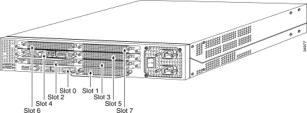


The T1 or E1 DFCs can be used in any of the DFC slots of the universal gateway chassis.
Determine the Type of DFC Installed in a Slot
To determine the type of DFC installed in a slot on the chassis, issue the show chassis command in privileged EXEC mode, a shown in this example:
Note: This example is taken from an AS5350. However, the output from an AS5400 is similar.
5400#show chassis slot detail

Slot 1:
DFC type is AS5350 NP108 DFC

OIR events:
        Number of insertions = 0, Number of removals = 0
DFC State is DFC_S_OPERATIONAL

Error events (Bus errors, PCI errors):
        Number of errors recovered = 0

!--- Output suppressed.


Slot 2:
DFC type is AS5350 Empty DFC
DFC is not powered

OIR events:
        Number of insertions = 0, Number of removals = 0

Error events (Bus errors, PCI errors):
        Number of errors recovered = 0

Carrier Card Cookie Info:
Manufacture Cookie Info:
 EEPROM Type 0x0001, EEPROM Version 0x01, Board ID 0x4D,
 Board Hardware Version 3.1, Item Number 73-3997-03,

!--- Output suppressed.


Tulum PLD Rev 0x001A

Slot 3:
DFC type is AS5350 Empty DFC
DFC is not powered

OIR events:
        Number of insertions = 0, Number of removals = 0

Error events (Bus errors, PCI errors):
        Number of errors recovered = 0

Carrier Card Cookie Info:
Manufacture Cookie Info:
 EEPROM Type 0x0001, EEPROM Version 0x01, Board ID 0x4D,
 Board Hardware Version 3.1, Item Number 73-3997-03,

!--- Output suppressed.
Figure 37 – Universal Port DFC (AS54-DFC-108NP /AS54-DFC-60NP)

The universal port DFC provides multiple port sessions. The number of sessions depends on the port density of the card. The DFC can be installed in any DFC slot of the universal gateway chassis. The DFC-108NP supports 108 modem connections, while the DFC-60NP supports 60 modem connections.
Internal Modems
The AS5400 access server supports only NextPort modems.
Display Modem Code Versions
Issue the show spe version command to list all modem code files in the boot Flash memory and system Flash memory, as well as the modem code files bundled with Cisco IOS Software. The show spe version command also displays the firmware version running on a particular SPE.
5400#show spe version
   IOS-Bundled Default Firmware-Filename      Version        Firmware-Type
   =====================================      ============   =============
   system:/ucode/np_spe_firmware1             0.6.108.0       SPE firmware

!--- The SPE version bundled with Cisco IOS Software is 6.108.


   On-Flash Firmware-Filename                 Version        Firmware-Type
   =====================================      ============   =============
   bootflash:np.7.15.spe                      0.7.15.0       SPE firmware

!--- Another SPE file (version 7.15) has been loaded in bootflash:.


     SPE-#   Type   Port-Range            Version   UPG Firmware-Filename
      1/00  CSMV6    0000-0005            0.7.15.0  N/A bootflash:np.7.15.spe

!--- SPE 1/00 uses the SPE code in bootflash: (version 7.15).

      1/01  CSMV6    0006-0011            0.6.108.0  N/A ios-bundled default

!--- All the other SPEs use the SPE code (6.108) bundled with Cisco IOS Software.

      1/02  CSMV6    0012-0017            0.6.108.0   N/A ios-bundled default
      1/03  CSMV6    0018-0023            0.6.108.0   N/A ios-bundled default
      1/04  CSMV6    0024-0029            0.6.108.0   N/A ios-bundled default

!--- Output suppressed.


      6/15  CSMV6    0090-0095            0.6.108.0   N/A ios-bundled default
      6/16  CSMV6    0096-0101            0.6.108.0   N/A ios-bundled default
      6/17  CSMV6    0102-0107            0.6.108.0   N/A ios-bundled default
For more information, refer to Understanding NextPort SPE Versions and NextPort SPE and IOS Software Version Reference Table.
AS5800
To help identify the modem and carrier card you have, you need to look at the front panel of the AS5800.
Figure 38 – Cisco AS5800-Front View 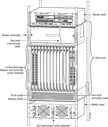
The access server includes a Cisco 5814 dial shelf and a Cisco 7206 router shelf.
Figure 39 – Cisco 5814 Dial Shelf 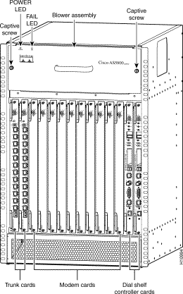
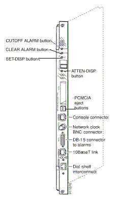
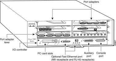
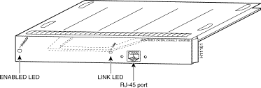
The Cisco AS5800 has a dial shelf interconnect port adapter that connects the Cisco 5814 dial shelf to the Cisco 7206 router shelf. The interconnect port adapter installs in any 7206 router shelf port adapter slot, and connects directly to the dial shelf controller card on the dial shelf using a single full-duplex cable.
Figure 43 – Channelized T1 or E1 Trunk Card (DS58-12CT1 / DS58-12CE1) 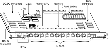
The Cisco AS5800 universal access server supports channelized T1 (CT1) and channelized E1 (CE1) interfaces. The CT1 and CE1 trunk cards are installed in the Cisco 5814 dial shelf in the AS5800.
Figure 44 – CT3 Trunk Card (DS58-1CT3) 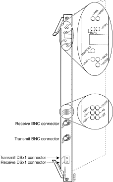
The Cisco AS5800 universal access server supports a channelized T3 (CT3). The CT3 trunk card is installed in the Cisco 5814 dial shelf chassis in slots 0 though 5.
Internal Modems
The AS5800 access server supports this internal modem:
Figure 45 – DMM Card (DS58-144CM-CC) 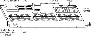
The Cisco AS5800 accommodates a maximum of 10 DMM cards. Each DMM card contains 12 DMM SIMMS. Each DMM SIMM contains 12 digital modems. Since there are 12 DMMs on each DMM modem card, each card can support a maximum of 144 modems. DMM cards can be found in slots numbered 0 through 11 on the dial shelf backplane.
Display Modem Code Versions
Issue the show spe version command to list all modem code files in the boot Flash memory and system Flash memory, as well as the modem code files bundled with Cisco IOS Software. The show spe version command also displays the firmware version running on a particular module.
5800#show modem version
 Modem Range             Module   Firmware Rev
    1/6/00 1/6/05          0      2.7.4.0

!--- MICA modems 1/6/00 through 1/6/05 have MICA portware 2.7.4.0 loaded on them.

    1/6/06 1/6/11          1      2.7.4.0
    1/6/12 1/6/17          2      2.7.4.0
    1/6/18 1/6/23          3      2.7.4.0
    1/6/24 1/6/29          4      2.7.4.0
    1/6/30 1/6/35          5      2.7.4.0
    1/6/36 1/6/41          6      2.7.4.0
    1/6/42 1/6/47          7      2.7.4.0
    1/6/48 1/6/53          8      2.7.4.0
    1/6/54 1/6/59          9      2.7.4.0
    1/6/60 1/6/65         10      2.7.4.0
    1/6/66 1/6/71         11      2.7.4.0
Modem board HW version info:

Modem Range:    1/6/00 1/6/05         Modem Module:  0
Manufacture Cookie Info:
 EEPROM Type 0x0101, EEPROM Version 0x01, Board ID 0x06,
 Board Hardware Version 1.0, Item Number 73-2522-2,
 Board Revision 051, Serial Number 06298557,
 PLD/ISP Version 255.255, Manufacture Date 17-Jul-1997.

!--- Output suppressed.


Modem Range:    1/6/66 1/6/71         Modem Module: 11
Manufacture Cookie Info:
 EEPROM Type 0x0101, EEPROM Version 0x01, Board ID 0x06,
 Board Hardware Version 1.0, Item Number 73-2522-2,
 Board Revision 051, Serial Number 06298008,
 PLD/ISP Version 255.255, Manufacture Date 17-Jul-1997.
Figure 46 – 324 Universal Port Card (UPC) Overview
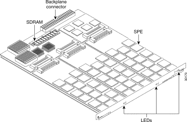
The 324 UPC uses NextPort hardware and firmware to provide universal ports for the Cisco AS5800 (the UPC is sometimes referred to as a NextPort module). These ports are grouped into SPEs, each of which supports six universal ports. There are 54 SPEs per UPC, for a total of 324 ports per UPC.
Display Modem Code Versions
Issue the show spe version command to list all modem code files in the boot Flash memory and system Flash memory, as well as the modem code files bundled with Cisco IOS Software. The show spe version command also displays the firmware version running on a particular SPE.
AS5800#show spe version
IOS-Bundled Default Firmware-Filename             Version  Firmware-Type
=====================================             =======  =============
system:/ucode/np_spe_firmware1                    0.6.6.9  SPE firmware

!--- The SPE version bundled with Cisco IOS Software is 0.6.6.9.


On-Flash Firmware-Filename                        Version  Firmware-Type
==========================                        =======  =============
slot0:np.spe_36                                   0.6.6.5  SPE firmware

!--- Another SPE file (version 0.6.6.5) has been loaded in slot0:.


  SPE-# SPE-Type   SPE-Port-Range     Version    UPG Firmware-Filename
1/04/00    CSMV6        0000-0005     0.6.6.9    N/A ios-bundled default

!--- SPE 1/04/00 uses the SPE code (version 0.6.6.9) that is bundled with Cisco IOS Software.

1/04/01    CSMV6        0006-0011     0.6.6.9    N/A ios-bundled default
1/04/02    CSMV6        0012-0017     0.6.6.9    N/A ios-bundled default
1/04/03    CSMV6        0018-0023     0.6.6.9    N/A ios-bundled default
1/04/04    CSMV6        0024-0029     0.6.6.9    N/A ios-bundled default
1/04/05    CSMV6        0030-0035     0.6.6.9    N/A ios-bundled default
1/04/06    CSMV6        0036-0041     0.6.6.9    N/A ios-bundled default
1/04/07    CSMV6        0042-0047     0.6.6.9    N/A ios-bundled default
1/04/08    CSMV6        0048-0053     0.6.6.9    N/A ios-bundled default

!--- Output suppressed.


1/04/50    CSMV6        0300-0305     0.6.6.9    N/A ios-bundled default
1/04/51    CSMV6        0306-0311     0.6.6.9    N/A ios-bundled default
1/04/52    CSMV6        0312-0317     0.6.6.9    N/A ios-bundled default
1/04/53    CSMV6        0318-0323     0.6.6.9    N/A ios-bundled default
For more information, refer to Understanding NextPort SPE Versions and NextPort SPE and IOS Software Version Reference Table.
AS5850
To help identify the modem and carrier card you have, you need to look at the front panel of the AS5850.
Figure 47 – Cisco AS5850-Front View 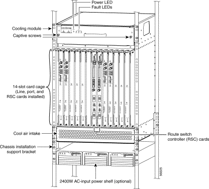
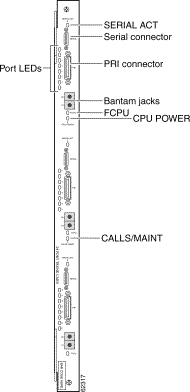
The 24 CT1/E1 trunk card provides physical termination for as many as 24 T1/E1 lines and connects to an external network termination (NT1) device.
Figure 49 – Channelized T3/216 Universal Port Card (AS58-1CT3/216U) 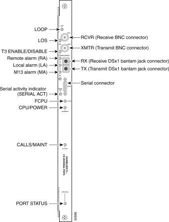
The Cisco AS5850 universal gateway supports a CT3 ingress interface card.
Figure 50 – 324 Universal Port Card (AS58-324UPC-CC) 
A universal port can carry the equivalent of one DS0 of network traffic. The core hardware components are SPEs, each of which supports six universal ports. There are 54 SPEs per UPC, for a total of 324 ports per UPC.
Internal Modems
The AS5850 access server supports only NextPort modems.
Display Modem Code Versions
Issue the show spe version command to list all modem code files in the boot Flash memory and system Flash memory, as well as the modem code files bundled with Cisco IOS Software. The show spe version command also displays the firmware version running on a particular SPE.
AS5850#show spe version
IOS-Bundled Default Firmware-Filename             Version  Firmware-Type
=====================================             =======  =============
system:/ucode/np_spe_firmware1                    0.6.6.9  SPE firmware

!--- The SPE version bundled with Cisco IOS Software is 0.6.6.9.


On-Flash Firmware-Filename                        Version  Firmware-Type
==========================                        =======  =============
slot0:np.spe_36                                   0.6.6.5  SPE firmware

!--- Another SPE file (version 0.6.6.5) has been loaded in slot0:.


  SPE-# SPE-Type   SPE-Port-Range     Version    UPG Firmware-Filename
1/04/00    CSMV6        0000-0005     0.6.6.9    N/A ios-bundled default

!--- SPE 1/04/00 uses the SPE code (version 0.6.6.9) that is bundled with Cisco IOS Software.

1/04/01    CSMV6        0006-0011     0.6.6.9    N/A ios-bundled default
1/04/02    CSMV6        0012-0017     0.6.6.9    N/A ios-bundled default
1/04/03    CSMV6        0018-0023     0.6.6.9    N/A ios-bundled default
1/04/04    CSMV6        0024-0029     0.6.6.9    N/A ios-bundled default
1/04/05    CSMV6        0030-0035     0.6.6.9    N/A ios-bundled default

!--- Output suppressed.


1/04/49    CSMV6        0294-0299     0.6.6.9    N/A ios-bundled default
1/04/50    CSMV6        0300-0305     0.6.6.9    N/A ios-bundled default
1/04/51    CSMV6        0306-0311     0.6.6.9    N/A ios-bundled default
1/04/52    CSMV6        0312-0317     0.6.6.9    N/A ios-bundled default
1/04/53    CSMV6        0318-0323     0.6.6.9    N/A ios-bundled default
For more information, refer to Understanding NextPort SPE Versions and NextPort SPE and IOS Software Version Reference Table.
Related Information
Revision History
| Revision | Publish Date | Comments |
|---|---|---|
1.0 |
04-Feb-2010 |
Initial Release |
Contact Cisco
- Open a Support Case

- (Requires a Cisco Service Contract)
 Feedback