Introduction
This document describes the concept of convergence with Topology Independent (TI) - Loop-Free Alternative (LFA) which is a highly focused feature. It details the mechanism of Segment Routing (SR) - Traffic Engineering (TE) policy path convergence with TI-LFA protection as an underlay with a topology diagram based on the requirements of XYZ Networks.
Link Failure Detection
Please note that SR-TE policy path convergence and TI-LFA features are independent of each other and function separately. However, the TI-LFA feature is added to make a quick detection of primary SR-TE policy path failure and a sub-50 msec of traffic switching to the pre-defined backup path under ideal network conditions. The SR-TE policy would work perfectly fine without TI-LFA, however, in that scenario the convergence number would depend solely on the Interior Gateway Protocol (IGP) and would be much higher than 50 msec.
Under the Link Failure scenario, our aim is to keep the convergence time as low as possible which would minimize the packet loss during the link down/flap event.
The detection of link down event at the headend node can happen mainly by these methods:
1. Detection at the Physical Layer in case of broken adjacent links.
2. Detection by BFD over Bundle in case of broken remote links.
In the first case, the detection is faster and the convergence time is lower than the second option where detection depends on configured BFD interval/dead timer and the exact network point where the link went down. However, a very fast detection does not necessarily mean as fast convergence since XYZ Org Network is a multi-layered structure with end-to-end service traffic that covers multiple hops.
Since XYZ Org network is contained within a single BGP AS and single IGP domain, here TI-LFA pre-defined backup paths immediately carry the failover traffic after a link failure in all scenarios and ensure minimum packet loss and complete prefix coverage irrespective of the topology state. The SR-TE policy-defined primary/secondary paths can take a while to converge due to IGP and ultimately take over the end-to-end service traffic through the core which can or can not match with the pre-defined paths of TI-LFA.
Detailed Convergence Scenarios
For further details, let’s understand the example detailed here that explains the traffic path with SR-TE policies and TI-LFA as the convergence mechanism of XYZ Org Network.
Sample SR Configuration Aligned with the Topology Diagrams:
segment-routing
 traffic-eng
   !
  !
  segment-list PrimaryPath1
   index 10 mpls adjacency 10.1.11.0 --> First Hop (P1 node) of the explicit-path
   index 20 mpls adjacency 10.1.3.1  --> Second Hop (P3 node) of the explicit-path
   index 30 mpls adjacency 10.3.13.1 --> Third Hop (PE3 node) of the explicit-path
  !
  policy POL1
  source-address ipv4 11.11.11.11          --> Source Node of the explicit-path
   color 10 end-point ipv4 33.33.33.33      --> Destination Node of the explicit-path
   candidate-paths
    preference 100         --> Secondary Path taken care of dynamically by IGP TI-LFA
     dynamic
      metric
       type igp
      !
     !
    !
    preference 200
     explicit segment-list PrimaryPath1   --> Primary Explicit-Path of the SR-TE policy
     !
    !
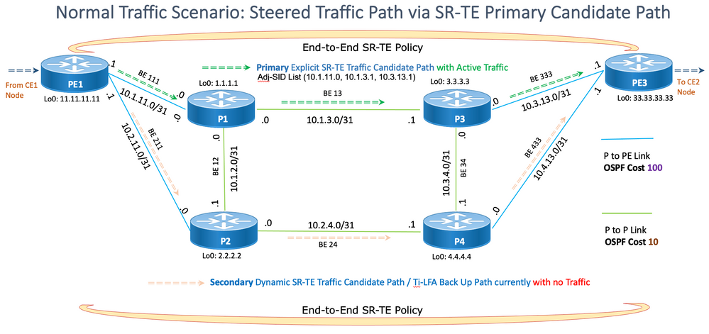
Under a normal scenario, the traffic must traverse from PE1 to PE3 via one of the two possible candidate paths PE1 > P1 > P3 > PE3 and PE1 > P2 > P4 > PE3 of the SR-TE policy, the primary explicit path as configured by the administrator with the Adjacency (Adj) - Segment Identifier (SID) List 10.1.11.0, 10.1.3.1, 10.3.13.1 or the secondary dynamic path as determined by the concerned IGP. The administrator prefers to use the primary candidate path and only fallback to the secondary path when the primary is down. So, a higher preference value is assigned to the primary candidate path which indicates a preferred path. For example, the primary candidate path can have a preference of 200 and the secondary candidate path has a preference of 100.
 Figure 1 : Normal Traffic Scenario SR-TE Primary Candidate Path
Any candidate path is used when it is valid, and the reachability of its constituent SIDs determines the validity criterion.
When both the candidate paths are valid and usable, the headend PE1 selects the higher preference path and installs the SID list of this path 10.1.11.0, 10.1.3.1, 10.3.13.1 in its forwarding table. At any point in time, the service traffic that is steered into this SR policy is only sent on the selected path, any other dynamic candidate paths are inactive.
A candidate path is selected when it has the highest preference value among all the valid candidate paths of the SR policy. The chosen path is also referred to as the ‘active path’ of the SR policy.
Link Failure Convergence - Primary Path Goes to Down State
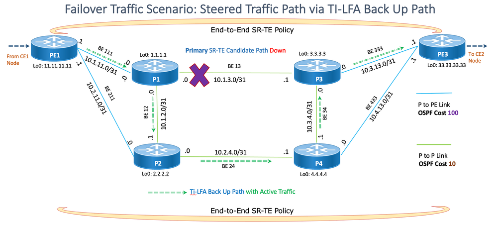
At some point, a link failure can occur in the network. The failed link can be a link between any two nodes, for example, P1 and P3. As soon as the failure is detected by any means as described at the beginning of the section, TI-LFA protection must ensure that the traffic flows are quickly redirected to the TI-LFA protection path, ideally within 50 msec.
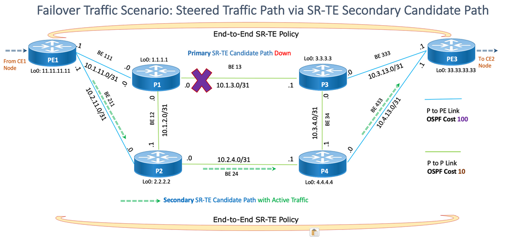
Please note that in this scenario, the backup path determined by TI-LFA as shown in Figure 2. is different from the ultimately converged backup policy path determined by IGP in Figure 3. This is fairly normal since the Ti-LFA backup path is locally determined by the Point Of Local Repair (PLR) node where failure has happened, however, the optimized SR-TE policy backup path is determined by the IGP convergence by the headend node which holds the SR-TE policy decisions.
 Figure 2 : Failover Traffic Scenario via TI-LFA Back-Up Path
The traffic continues to flow through the TI-LFA protection path until eventually, the headend PE1 learns via IGP flooding that the SID 10.1.3.1 of the failed link has become invalid. PE1 then evaluates the validity of the path’s SID list 10.1.11.0, 10.1.3.1, 10.3.13.1 and invalidates it due to the presence of the invalid SID 10.1.3.1. Simultaneously it invalidates the candidate path and re-executes the SR-TE policy’s path selection process. PE1, subsequently, selects another valid candidate path with the next highest preference value and installs the SID list 10.2.11.0, 10.2.4.1, 10.4.13.1 of the new secondary candidate path in the forwarding table. However, this secondary candidate path is dynamic in nature, determined by IGP Open Shortest Path First (OSPF), and has no administrative control. Till this step, the traffic flows via the protected TI-LFA path; but after this, it is steered into the newly preferred secondary path of the SR-TE policy.
 Figure 3 : Failover Traffic Scenario via SR-TE Secondary Candidate Path
Summary Steps:
1. On the point of failure:
- Layer1/BFD signals the primary path down to FIB
- FIB pushes to HW the backup path established with TI-LFA
- Expected traffic outage:
- Link down: ~50ms
- BFD peer loss: BFD dead time + ~50ms
- OSPF peering over lost link goes down
2. All OSPF routers in the domain learn of SID loss via Link State Advertisement (LSA) flooding
3. On SR-TE headend PE1:
- OSPF converges
- SR-TE policy Primary Path SID List gets invalidated
- The path of the Primary candidate goes down
- The secondary candidate path SID List is validated, and it becomes active
- Traffic is sent via a secondary path without any service traffic loss
Link Failure Re-Convergence - Primary Path Back to Up State
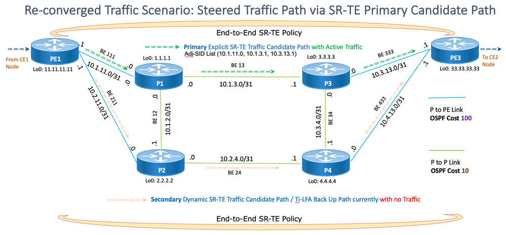
Meanwhile, once the primary failed link gets restored, the original primary path with preference (200) becomes valid again and so the headend PE1 performs the SR-TE policy path selection procedure, selects the valid explicit candidate path with the highest preference and updates its forwarding table with the original primary path’s SID list. The service traffic that is steered into this SR policy is sent on the original path PE1 > P1 > P3 > PE3 again.
 Figure 4 : Re-Converged Traffic Scenario
Summary Steps:
1. Layer 1/BFD signals the primary path back up and OSPF gets notified.
2. Traffic is still forwarded through the SR-TE policy backup candidate-path.
3. After a while, the SID List of SR-TE policy primary candidate-path gets valid via OSPF LSA flooding.
4. Traffic is switched from the SR-TE policy backup candidate path to the SR-TE policy primary candidate path with zero traffic loss.
To conclude, these scenarios provide a theoretical explanation of the convergence process and ideal convergence numbers; however, you need to test the actual convergence numbers in the lab that mimic the production network and configuration as closely as feasible and trigger different failure points in the network which one can foresee.

Caution: Please note that this document explains only Link Protection scenarios since Node Protection does not work with SR-TE explicit paths if the defined explicit path touches intermediate nodes. This is because TI-LFA takes each configured intermediate hop as the destination node and in case any of those fails it is not able to resolve the final destination. This is a technology limitation and is not restricted to any platform or image version. The solution for this limitation has been discussed in Part 2 of this document as mentioned in the Related Information section.
Software Used
The software used to test and validate the solution isCisco IOS®XR 7.3.2.
Related Information


 Feedback