Troubleshoot EDID and Camera Connection Issue on an Endpoint
Available Languages
Download Options
Bias-Free Language
The documentation set for this product strives to use bias-free language. For the purposes of this documentation set, bias-free is defined as language that does not imply discrimination based on age, disability, gender, racial identity, ethnic identity, sexual orientation, socioeconomic status, and intersectionality. Exceptions may be present in the documentation due to language that is hardcoded in the user interfaces of the product software, language used based on RFP documentation, or language that is used by a referenced third-party product. Learn more about how Cisco is using Inclusive Language.
Contents
Introduction
This document describes how to troubleshoot issues with cameras connected to a cloud-registered endpoint that is caused by EDID.
Prerequisites
Requirements
It is recommended that you have some familiarity with these topics:
- Control Hub Platform
- Endpoint Administration via the Graphical User Interface (GUI) of the endpoint and Control Hub "Devices" section
- RoomOS
- HDMI Cabling
Components Used
The equipment listed here has been used to make the tests and produce the results described in this document:
- Codec Pro endpoint
- 2 PTZ 4K cameras mounted on the wall (one of the cameras is mounted on normal orientation while the second one is upside-down).
- Cameras are connected via LAN to the endpoint but no ethernet cables are directly connected from the endpoint to the camera. A transmitter/receiver device has been used.
- Control Hub Organization
The information in this document was created from the devices in a specific lab environment. All of the devices used in this document started with a cleared (default) configuration. If your network is live, ensure that you understand the potential impact of any command.
EDID Basic Explanation
EDID or Extended Display Identification Data is a digital handshake used when you connect two devices (a media device and a display device) using an HDMI cable. This handshake is used from the connected devices to negotiate parameters like framerate, resolution, and audio standards that they support. The negotiation results in a mutually supported list of parameters that are going to be used for transmitting the video and audio content between each other over the HDMI cable. The handshake initiates once both devices have fully booted-up and they both attempt to achieve the best possible results (best resolution, framerate, and other parameters that can be mutually supported from both sides). This handshake is done in the background. It takes place very fast and has no visible results to the user while it is happening. It is practically instantaneous for a 1-2 meter HDMI cable with no intermediate devices in between.
Description of the Exact Scenario
In a modern conference room setup, there is a variety of different devices that can be used to achieve the best possible result. Parameters like room size, view angles, and the number of cameras and microphones affect the final setup and the result you can get from the utilization of the endpoint. In cases, where the room size is considerable, placing the cameras and other peripherals next to or near the endpoint is not always possible as this type of setup cannot offer the optimal meeting experience for all the users that can occupy the room at the same time.
For this reason, there are cases that the cameras need to be placed at a relatively large distance from where the endpoint is setup. For the cameras to be able to be connected back to the endpoint HDMI input ports, many different alternatives can be used, some of which are:
- Using a longer HDMI cable than the standard 1 or 2 meter.
- Connecting multiple HDMI cables, using HDMI splitters or extenders to cover the distance to the endpoint.
- Using HDMI switches.
Certain issues come up in the scenario described. When using longer HDMI cables exceeding 2 meters or when extenders and splitters are used, the longer distance that the EDID signals have to travel along the cable introduces loss. This can result in the negotiation of EDID not being successful or not giving the expected outcome. In addition to this, intermediate devices sometimes, depending on the device type, configuration, and capabilities, do not pass the EDID information correctly or at all to the other side of the connection. PTZ cameras, along with other cameras connected via HDMI to the endpoints can be directly affected, thus having the EDID passing to the endpoint the wrong parameters.
This is not always fully visible to the end user, but in the example examined in this article, you are assuming that you have two PTZ 4K cameras on opposite sides of a room and you want to mount Camera 1 with normal orientation and Camera 2 upside-down, mounted on the ceiling of the room (shown here):
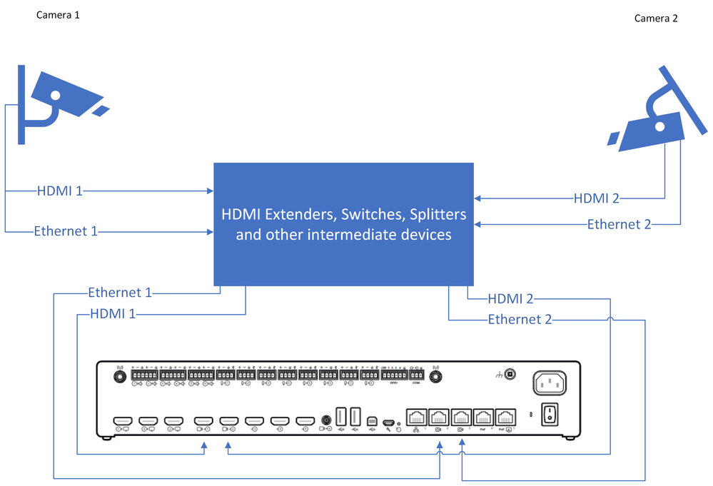 Connection Diagram

Note: The power supply cables for the cameras in this diagram have been omitted for simplicity.
For Camera 2 to be able to show video footage in the proper orientation and not upside down, you need to utilize the feature "Cameras Camera [n] Flip" (this feature is not supported by all cameras, but it is supported by specific models of PTZ 4K). With this specific setup, depending on how EDID is negotiated, notice that both cameras are providing upside-down video. Your immediate thought is that the "Cameras Camera [n] Flip" feature is not working but the issue is a bit more complicated.

Note: In this article, it is used the naming of the endpoint features in this form: "Cameras Camera [n] Flip" feature. This is because on the official RoomOS Administration Guide for cloud-registered devices, you can locate these features by searching them in this form. They are documented in this exact way. This form represents the path that the administrator has to follow in the Control Hub Configuration settings or the configuration settings on the device GUI to locate and change each feature. For example, for the "Cameras Camera [n] Flip" feature we see the path followed in the settings in the picture here (administration guide page 212):
![Cameras Camera [n] Flip feature Configuration in Control Hub](/c/dam/en/us/support/docs/collaboration-endpoints/telepresence-precision-cameras/221771-troubleshoot-edid-and-camera-connection-01.png) Cameras Camera [n] Flip feature Configuration in Control Hub
Cameras Camera [n] Flip feature Configuration in Control Hub
In the RoomOS admin guide for endpoints running RoomOS 11.9 you can see the feature described in this manner:
![Cameras Camera [n] Flip feature description in the Administration Guide](/c/dam/en/us/support/docs/collaboration-endpoints/telepresence-precision-cameras/221771-troubleshoot-edid-and-camera-connection-02.png) Cameras Camera [n] Flip feature description in the Administration Guide
Cameras Camera [n] Flip feature description in the Administration GuideThe "Cameras Camera [n] Flip" feature can be found on a Codec Pro device that is cloud-registered by going to the "Devices" section under Management in your Control Hub Organization and choosing the Codec Pro device from the list of devices.
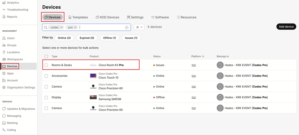 Control Hub Devices section
Then navigate to the "Configurations" section and select "All Configurations" as seen in this picture:
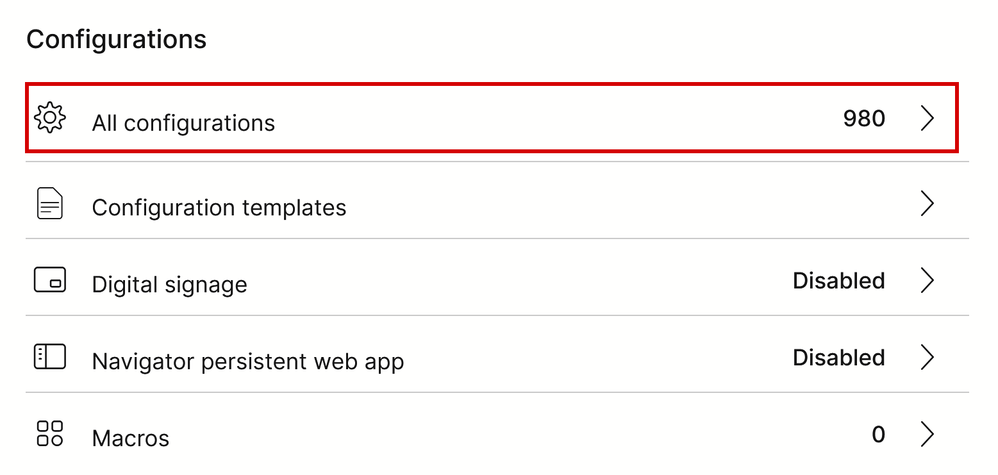 Endpoint Configuration section in Control Hub
In the search bar in the new window, search for the feature's name:
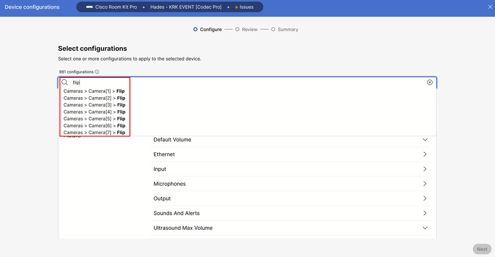 Individual Device Configurations menu in Control Hub
From the list in the drop-down menu, choose the camera that is deployed upside-down. In the scenario described in the article, it is Camera 2 (See the connection diagram presented previously). Then turn the feature On and click "Next":
![Cameras Camera [n] Flip feature Configuration in Control Hub](/c/dam/en/us/support/docs/collaboration-endpoints/telepresence-precision-cameras/221771-troubleshoot-edid-and-camera-connection-06.png) Cameras Camera [n] Flip feature Configuration in Control Hub
Cameras Camera [n] Flip feature Configuration in Control Hub
Then verify the change you are making is correct and click "Apply":
![Cameras Camera [n] Flip feature Review in Control Hub](/c/dam/en/us/support/docs/collaboration-endpoints/telepresence-precision-cameras/221771-troubleshoot-edid-and-camera-connection-07.png) Cameras Camera [n] Flip feature Review in Control Hub
Cameras Camera [n] Flip feature Review in Control Hub
How to Proceed with Troubleshooting
Based on the connection diagram, the cables are physically connected to the endpoint as:
- Camera 1 (Horizontal camera) => Connected to HDMI Input Connector 1
- Camera 2 (Upside-down camera) => Connected to the HDMI Input Connector 2
Based on the configuration done up to this point, it is logical to assume that the "Cameras Camera [n] Flip" feature is not working as expected. If you collect the endpoint logs, you can see:
*s Cameras Camera 1 DetectedConnector: 2
*s Cameras Camera 2 DetectedConnector: 1
Camera 1 is detected at Connector 2, but it is physically connected to Connector 1. Camera 2 is detected at Connector 1, but it is physically connected to Connector 2.

Tip: A simple way to tell if the cameras are recognized from the endpoint in reverse than the way you have connected them to it, without any logs, is to try and control the cameras from the Navigator or Touch 10 device connected to the endpoint. When you try to control Camera 1, Camera 2 is responding. When you try and Control Camera 2, Camera 1 is responding. This way you know that something is not working as expected.
This means that the "Cameras Camera [n] Flip" feature change has been enforced on Camera 1 (with Horizontal orientation), and this is the reason why it shows us the upside-down footage. Camera 2 on the other hand is upside-down itself with no modification to its settings, thus it is showing us the image as is. So at this stage, both cameras show the video footage upside-down.
This is happening because the EDID information used to identify where each camera is connected is not propagated correctly from each of the HDMI connections that initiate from the cameras to the endpoint. Intermediate devices used to connect the cameras to the endpoint via HDMI usually play a role in this result.
How to Resolve the Issue
To resolve this issue you need to properly configure the "AssignedSerialNumber" feature on the Codec Pro settings. This feature allows you to manually configure the Serial Number of each camera to its camera id (Camera 1 must have a camera id equal to 1, and Camera 2 must have a camera id equal to 2). The camera ID is the number n in Camera [n]. By default, the camera ID is assigned automatically to a camera. If EDID information is not passed on from the camera to the video device, there is a chance that the camera ID does not match the actual way that the cameras are physically connected on the endpoint. Because of this, when trying to apply a configuration to Camera 1, Camera 2 is affected one, and vice versa.

Caution: The configuration of the "AssignedSerialNumber" feature is persistent after the endpoint reboots. However, it is not persistent if you factory reset the device, and in this case, you need to reconfigure it again, as the issue is going to re-emerge.
This is the "AssignedSerialNumber" feature description as described in the administration guide on page 209 for RoomOS 11.9:
![Cameras Camera [n] AssignedSerialNumber in the Administration Guide](/c/dam/en/us/support/docs/collaboration-endpoints/telepresence-precision-cameras/221771-troubleshoot-edid-and-camera-connection-08.png) Cameras Camera [n] AssignedSerialNumber in the Administration Guide
Cameras Camera [n] AssignedSerialNumber in the Administration Guide
To find the "AssignedSerialNumber" feature, you need to access the device configurations from Control Hub as described earlier in this article for the "Cameras Camera [n] Flip" feature. Search for the feature's name in the search bar:
![Cameras Camera [n] AssignedSerialNumber Configuration in Control Hub](/c/dam/en/us/support/docs/collaboration-endpoints/telepresence-precision-cameras/221771-troubleshoot-edid-and-camera-connection-09.png) Cameras Camera [n] AssignedSerialNumber Configuration in Control Hub
Cameras Camera [n] AssignedSerialNumber Configuration in Control Hub
At this stage, you need to select the cameras affected. For the scenario of this article, it is Camera 1 and Camera 2. It does not matter which camera you choose first. Camera 1 is detected at Connector 2, but it is physically connected to Connector 1. Camera 2 is detected at Connector 1 but it is physically connected to Connector 2. You need to know which camera is physically connected to which HDMI Input port. Select Assigned Serial Number for Camera 1 (The serial Number seen in this picture is not valid, it is a random number for demonstration purposes). Then input the serial number of Camera 1 that is connected to HDMI Input port 1 of the endpoint, and click "Next".
![Cameras Camera [n] AssignedSerialNumber Configuration in Control Hub](/c/dam/en/us/support/docs/collaboration-endpoints/telepresence-precision-cameras/221771-troubleshoot-edid-and-camera-connection-10.png) Cameras Camera [n] AssignedSerialNumber Configuration in Control Hub
Cameras Camera [n] AssignedSerialNumber Configuration in Control Hub
Then, click "Apply" in the "Review Configurations" page:
![Cameras Camera [n] AssignedSerialNumber Review in Control Hub](/c/dam/en/us/support/docs/collaboration-endpoints/telepresence-precision-cameras/221771-troubleshoot-edid-and-camera-connection-11.png) Cameras Camera [n] AssignedSerialNumber Review in Control Hub
Cameras Camera [n] AssignedSerialNumber Review in Control Hub
Perform the same procedure for Camera 2 using the Serial Number of Camera 2, but make sure to select the Assigned Serial Number for Camera 2 from the device configurations page.
![Cameras Camera [n] AssignedSerialNumber Configuration in Control Hub](/c/dam/en/us/support/docs/collaboration-endpoints/telepresence-precision-cameras/221771-troubleshoot-edid-and-camera-connection-12.png) Cameras Camera [n] AssignedSerialNumber Configuration in Control Hub
Cameras Camera [n] AssignedSerialNumber Configuration in Control Hub

Caution: Codec Pro supports up to 7 cameras, and the Assigned Serial Number feature is distinct for each camera. So you need to manually set the serial number for each camera when facing this issue.
At this stage, your issue is resolved and Camera 1 is mapped correctly to HDMI Input port 1, where it is physically connected. Camera 2 is mapped to HDMI Input port 2, where it is physically connected.
If the issue is still present, you must check the "Cameras Camera [n] Flip" feature on Camera 1 and Camera 2 and make sure that it is enabled only for the camera that is set up upside-down, which in the scenario examined here is Camera 2. Also, you can try to reboot the endpoint. Your configuration remains unaffected. If you Factory reset the endpoint, all configurations need to be performed again.
How to Perform This Procedure from the Endpoint's GUI
Access your endpoint's GUI either by Control Hub or by typing the device's IP address on a browser tab and log in with admin user credentials. Then navigate to "Settings" under "Setup" section and choose the "Configurations" tab. On the search bar within the page type "flip". The configurations for the "Cameras Camera [n] Flip" feature can be performed for the camera needed (Camera 2 for the example presented in this article). Then click "Save".
![Cameras Camera [n] Flip Configuration in Endpoint GUI](/c/dam/en/us/support/docs/collaboration-endpoints/telepresence-precision-cameras/221771-troubleshoot-edid-and-camera-connection-13.png) Cameras Camera [n] Flip Configuration in Endpoint GUI
Cameras Camera [n] Flip Configuration in Endpoint GUI
For the "AssignedSerialNumber" feature, Navigate in the same exact menu, and in the search bar type "assigned" instead. Assign manually the Serial number to each camera and click "Save".
![Cameras Camera [n] AssignedSerialNumber Configuration in Endpoint GUI](/c/dam/en/us/support/docs/collaboration-endpoints/telepresence-precision-cameras/221771-troubleshoot-edid-and-camera-connection-14.png) Cameras Camera [n] AssignedSerialNumber Configuration in Endpoint GUI
Cameras Camera [n] AssignedSerialNumber Configuration in Endpoint GUI
How to Locate the Serial Number of a Camera Connected to an Endpoint
In this last section, it is shown how the serial number of a camera connected to a cloud-registered endpoint can be found. There are 3 ways to find the camera serial number:
- In the endpoint's GUI
- In Control Hub
- In the device logs
Serial Number of a Camera in the Endpoint's GUI
Access your endpoint's GUI either by Control Hub or by typing the device's IP address on a browser tab and log in with admin user credentials. Then navigate to "Settings" under "Setup" section and choose the "Audio and Video" tab. Then, select the first tab called "Cameras":
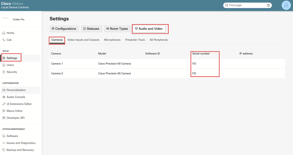 Endpoint Peripheral details on Endpoint GUI
Under this menu, you can see information about your cameras (in the picture shared previously, all IPs and Serial Numbers have been hidden on purpose, on your endpoint's GUI this information is going to be present) along with the Serial numbers. Copy and paste each number and use it in your Control Hub or endpoint GUI when setting up the Assigned Serial Number feature for each camera.

Note: A question that can arise at this stage is that if the cameras are recognized in reverse than the way they are connected, then the Serial Numbers of each camera must be mapped in the GUI, and Control Hub, in reverse order too. However, you can not be sure about that. Serial numbers can be transferred successfully from the cameras to the endpoint and another EDID parameter can be the one missing leading to the mapping of the devices not being the expected one. Due to this fact, you need to first try to copy-paste the Serial Number from Camera 1 to the AssignedSerialNumber of Camera 1 and the Serial Number from Camera 2 to the AssignedSerialNumber of Camera 2. If it does not work, then copy-paste the Serial Number of Camera 1 to AssignedSerialNumber of Camera 2 and vice versa.
Serial Number of a Camera in Control Hub
Login to your Control Hub Organization and navigate to "Devices" under the Management section. Select your device from the device list and navigate to "Connected Peripherals".
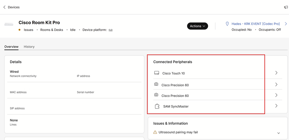 Endpoint Peripheral details in Control Hub
Select one of your cameras. You land on this menu where you can see the serial number of the camera:
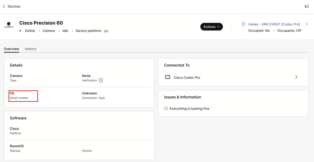 Camera details in Control Hub
Copy and paste the serial number and use it in your Control Hub or endpoint GUI when setting up the Assigned Serial Number feature for this camera. Perform the same to find the serial number of the second camera.
Serial Number of a Camera in the Device Logs
Access your endpoint's GUI either by Control Hub or by typing the device's IP address on a browser tab and log in with admin user credentials. Navigate to "Issues and Diagnostics" and select the "System Logs" tab. Then, click on the down arrow next to the "Download Logs" button and select "Full Logs". A log file is then downloaded.
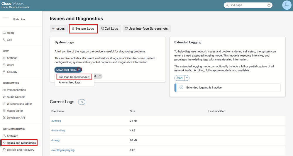 Log Collection from Endpoint GUI
Decompress the Log file and locate the file named "peripherals". Open the file in your preferred note application. The lines shown in the picture contain the Serial number of the cameras connected to the endpoint (All other information has been omitted on purpose).
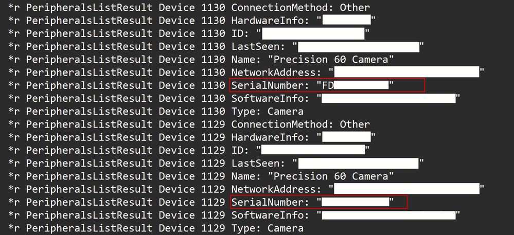 Peripheral Log file inspection
Copy and paste each number and use it in your Control Hub or endpoint GUI when setting up the Assigned Serial Number feature for each camera.

Note: Sometimes the Serial number of the camera is identical to the MAC address it is assigned to it. This is not a bug. It is expected to happen for specific types of cameras and is by design.
Codec Pro vs Room Kit Pro
You can notice that in this article, it is mentioned that a Codec Pro is used, but in the pictures shared from Control Hub you can see a Room Kit Pro. This is because Room Kit Pro is a device bundle that contains Codec Pro (sold also separately as a single unit) along with peripheral devices like Cameras, Navigator touch panel and so on. The endpoint unit in the Room Kit Pro bundle is the Codec Pro and this is why it is mentioned as such. The Room Kit Pro Data Sheet explaining this in more detail can be found in the link here
Related information
PTZ 4K Camera installation guide
Administration Guide for Cisco collaboration devices running RoomOS 11.9
Revision History
| Revision | Publish Date | Comments |
|---|---|---|
1.0 |
04-Mar-2024 |
Initial Release |
Contributed by Cisco Engineers
- Petros SitarasTechnical Consulting Engineer
Contact Cisco
- Open a Support Case

- (Requires a Cisco Service Contract)
 Feedback