Replacement of Compute Server UCS C240 M4 - CPAR
Available Languages
Download Options
Bias-Free Language
The documentation set for this product strives to use bias-free language. For the purposes of this documentation set, bias-free is defined as language that does not imply discrimination based on age, disability, gender, racial identity, ethnic identity, sexual orientation, socioeconomic status, and intersectionality. Exceptions may be present in the documentation due to language that is hardcoded in the user interfaces of the product software, language used based on RFP documentation, or language that is used by a referenced third-party product. Learn more about how Cisco is using Inclusive Language.
Contents
Introduction
This document describes the steps required to replace a faulty compute server in an Ultra-M setup.
This procedure applies for an Openstack environment using NEWTON version where Elastic Serives Controller (ESC) does not manage Cisco Prime Access Registrar (CPAR) and CPAR is installed directly on the VM deployed on Openstack.
Background Information
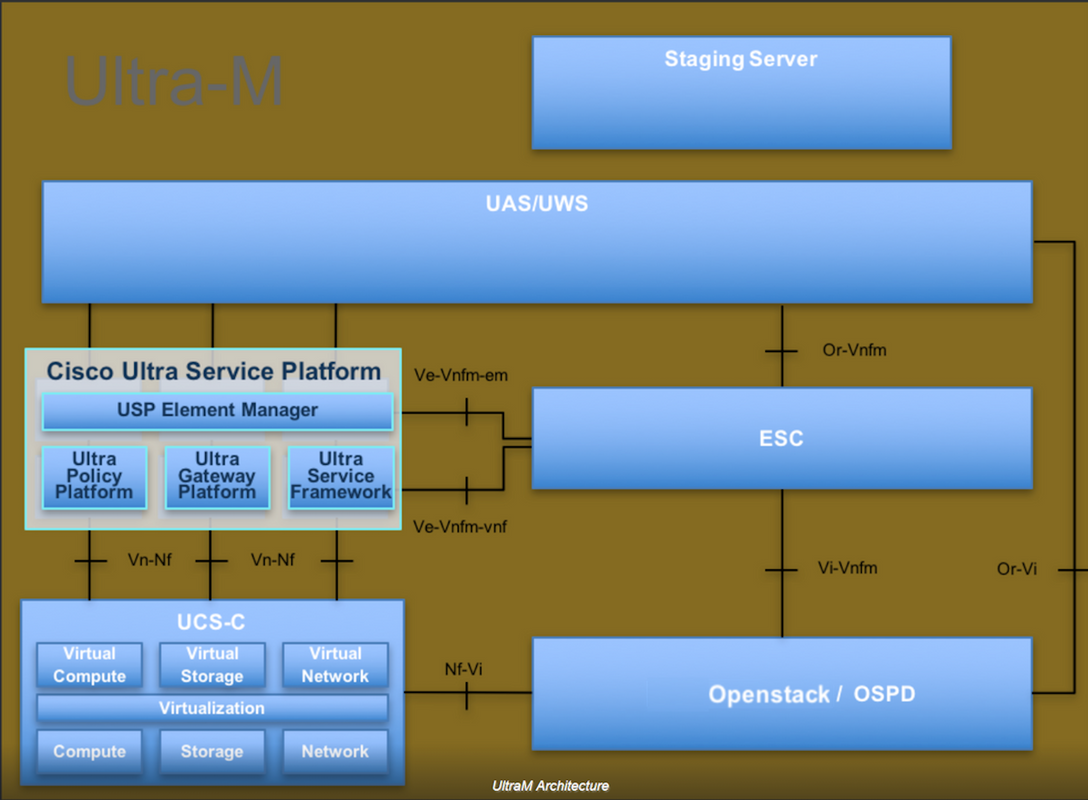
Ultra-M is a pre-packaged and validated virtualized mobile packet core solution that is designed in order to simplify the deployment of VNFs. OpenStack is the Virtualized Infrastructure Manager (VIM) for Ultra-M and consists of these node types:
- Compute
- Object Storage Disk - Compute (OSD - Compute)
- Controller
- OpenStack Platform - Director (OSPD)
The high-level architecture of Ultra-M and the components involved are depicted in this image:
This document is intended for Cisco personnel who are familiar with Cisco Ultra-M platform and it details the steps required to be carried out at OpenStack and Redhat OS.
Note: Ultra M 5.1.x release is considered in order to define the procedures in this document.
Abbreviations
| MOP | Method of Procedure |
| OSD | Object Storage Disks |
| OSPD | OpenStack Platform Director |
| HDD | Hard Disk Drive |
| SSD | Solid State Drive |
| VIM | Virtual Infrastructure Manager |
| VM | Virtual Machine |
| EM | Element Manager |
| UAS | Ultra Automation Services |
| UUID | Universally Unique IDentifier |
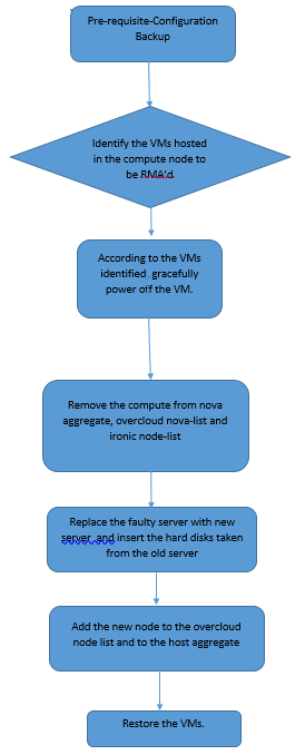
Workflow of the MoP
Prerequisites
Backup
Before you replace a Compute node, it is important to check the current state of your Red Hat OpenStack Platform environment. It is recommended you check the current state in order to avoid complications when the Compute replacement process is on. It can be achieved by this flow of replacement.
In case of recovery, Cisco recommends to take a backup of the OSPD database with the use of these steps:
[root@ al03-pod2-ospd ~]# mysqldump --opt --all-databases > /root/undercloud-all-databases.sql
[root@ al03-pod2-ospd ~]# tar --xattrs -czf undercloud-backup-`date +%F`.tar.gz /root/undercloud-all-databases.sql
/etc/my.cnf.d/server.cnf /var/lib/glance/images /srv/node /home/stack
tar: Removing leading `/' from member names
This process ensures that a node can be replaced without affecting the availability of any instances.
Note: Ensure that you have the snapshot of the instance so that you can restore the VM when needed. Follow the below procedure on how to take snapshot of the VM.
Identify the VMs Hosted in the Compute Node
Identify the VMs that are hosted on the compute server.
[stack@al03-pod2-ospd ~]$ nova list --field name,host

+--------------------------------------+---------------------------+----------------------------------+

| ID                                   | Name                      | Host                             |

+--------------------------------------+---------------------------+----------------------------------+

| 46b4b9eb-a1a6-425d-b886-a0ba760e6114 | AAA-CPAR-testing-instance | pod2-stack-compute-4.localdomain |

| 3bc14173-876b-4d56-88e7-b890d67a4122 | aaa2-21                   | pod2-stack-compute-3.localdomain |

| f404f6ad-34c8-4a5f-a757-14c8ed7fa30e | aaa21june                 | pod2-stack-compute-3.localdomain |

+--------------------------------------+---------------------------+----------------------------------+
Note: In the output shown here, the first column corresponds to the Universally Unique IDentifier (UUID), the second column is the VM name and the third column is the hostname where the VM is present. The parameters from this output will be used in subsequent sections.
Snapshot Process
CPAR Application Shutdown
Step 1. Open any SSH client connected to the network and connect to the CPAR instance.
It is important not to shutdown all 4 AAA instances within one site at the same time, do it in a one by one fashion.
Step 2. Shut Down CPAR application with this command:
/opt/CSCOar/bin/arserver stop
A Message states “Cisco Prime Access Registrar Server Agent shutdown complete.” should show up.
Note: If a user left a CLI session open, the arserver stop command won’t work and the following message will be displayed:
ERROR:    You can not shut down Cisco Prime Access Registrar while the
          CLI is being used.   Current list of running
          CLI with process id is:
2903 /opt/CSCOar/bin/aregcmd –s
In this example, the highlighted process id 2903 needs to be terminated before CPAR can be stopped. If this is the case, terminate the process with this command:
kill -9 *process_id*
Then repeat the step 1.
Step 3. Verify that CPAR application was indeed shutdown by this command:
/opt/CSCOar/bin/arstatus
These messages should appear:
Cisco Prime Access Registrar Server Agent not running
Cisco Prime Access Registrar GUI not running
VM Snapshot Task
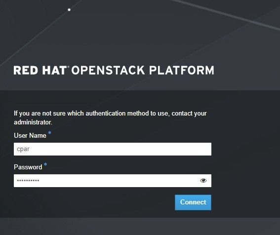
Step 1. Enter the Horizon GUI website that corresponds to the Site (City) currently being worked on. When the Horizon is accessed, the screen shown in the image is observed:
Step 2. As shown in the image, navigate to Project > Instances.

If the user used was cpar, then only the 4 AAA instances will appear in this menu.
Step 3. Shut down only one instance at a time, repeat the whole process in this document. In order to shutdown the VM, navigate to Actions > Shut Off Instance and confirm your selection.

Step 4 Validate that the instance was indeed shut down through Status = Shutoff and Power State = Shut Down.

This step ends the CPAR shutdown process.
VM Snapshot
Once the CPAR VMs are down, the snapshots can be taken in parallel, as they belong to independent computes.
The four QCOW2 files are created in parallel.
Take a snapshot of each AAA instance (25 minutes -1 hour) (25 minutes for instances that used a qcow image as a source and 1 hour for instances that user a raw image as a source).
Step 1. Login to POD’s Openstack’s Horizon GUI.
Step 2. Once logged in, proceed to the Project > Compute > Instances, section on the top menu and look for the AAA instances.
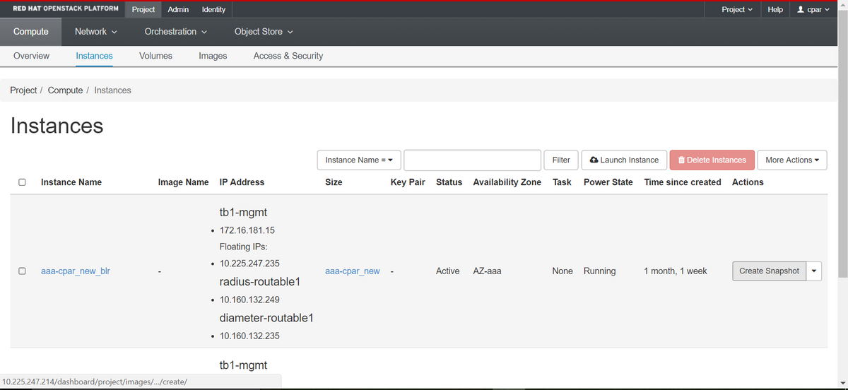
Step 3. Click on the Create Snapshot to proceed with snapshot creation (this needs to be executed on the corresponding AAA instance).
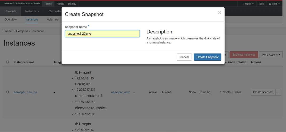
Step 4. Once the snapshot is executed, navigate to the Images menu and verify that it finishes and reports no problems.
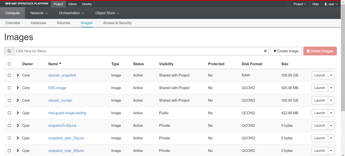
Step 5. The next step is to download the snapshot on a QCOW2 format and transfer it to a remote entity in case the OSPD is lost during this process. In order to achieve this, identify the snapshot with this command glance image-list at OSPD level
[root@elospd01 stack]# glance image-list

+--------------------------------------+---------------------------+

| ID                                   | Name                      |             +--------------------------------------+---------------------------+

| 80f083cb-66f9-4fcf-8b8a-7d8965e47b1d | AAA-Temporary             |             | 22f8536b-3f3c-4bcc-ae1a-8f2ab0d8b950 | ELP1 cluman 10_09_2017    |

| 70ef5911-208e-4cac-93e2-6fe9033db560 | ELP2 cluman 10_09_2017    |

| e0b57fc9-e5c3-4b51-8b94-56cbccdf5401 | ESC-image                 |

| 92dfe18c-df35-4aa9-8c52-9c663d3f839b | lgnaaa01-sept102017       |

| 1461226b-4362-428b-bc90-0a98cbf33500 | tmobile-pcrf-13.1.1.iso   |

| 98275e15-37cf-4681-9bcc-d6ba18947d7b | tmobile-pcrf-13.1.1.qcow2 |

+--------------------------------------+---------------------------+
Step 6. Once identified the snapshot to be downloaded (in this case is going to be the one marked above in green), it is downloaded on a QCOW2 format through this command glance image-download as shown here.
[root@elospd01 stack]# glance image-download 92dfe18c-df35-4aa9-8c52-9c663d3f839b --file /tmp/AAA-CPAR-LGNoct192017.qcow2 &
- The “&” sends the process to background. It takes some time to complete this action, once it is done, the image can be located at /tmp directory.
- When the process is sent to the background, if connectivity is lost, then the process is also stopped.
- Run the command disown -h so that in case Secure Shell (SSH) connection is lost, the process still runs and finishes on the OSPD.
Step 7. Once the download process finishes, a compression process needs to be executed as that snapshot may be filled with ZEROES because of processes, tasks and temporary files handled by the Operating System. The command to be used for file compression is virt-sparsify.
[root@elospd01 stack]# virt-sparsify AAA-CPAR-LGNoct192017.qcow2 AAA-CPAR-LGNoct192017_compressed.qcow2
This process takes some time (around 10-15 minutes). Once finished, the resulting file is the one that needs to be transferred to an external entity as specified on next step.
Verification of the file integrity is required, in order to achieve this, run the next command and look for the corrupt attribute at the end of its output.
[root@wsospd01 tmp]# qemu-img info AAA-CPAR-LGNoct192017_compressed.qcow2
image: AAA-CPAR-LGNoct192017_compressed.qcow2
file format: qcow2
virtual size: 150G (161061273600 bytes)
disk size: 18G
cluster_size: 65536
Format specific information:

    compat: 1.1

    lazy refcounts: false

    refcount bits: 16

    corrupt: false
In order to avoid a problem where the OSPD is lost, the recently created snapshot on QCOW2 format needs to be transferred to an external entity. Before to start the file transfer we have to check if the destination have enough available disk space, use the command df –kh, in order to verify the memory space. It is advised to transfer it to another site’s OSPD temporarily through SFTP sftp root@x.x.x.x where x.x.x.x is the IP of a remote OSPD. In order to speed up the transfer, the destination can be sent to multiple OSPDs. In the same way, this command can be used scp *name_of_the_file*.qcow2 root@ x.x.x.x:/tmp (where x.x.x.x is the IP of a remote OSPD) to transfer the file to another OSPD.
Graceful Power Off
Power off Node
- To power off the instance : nova stop <INSTANCE_NAME>
- Now you see the instance name with the status shutoff.
[stack@director ~]$ nova stop  aaa2-21

Request to stop server aaa2-21 has been accepted.

[stack@director ~]$ nova list

+--------------------------------------+---------------------------+---------+------------+-------------+------------------------------------------------------------------------------------------------------------+

| ID                                   | Name                      | Status  | Task State | Power State | Networks                                                                                                   |

+--------------------------------------+---------------------------+---------+------------+-------------+------------------------------------------------------------------------------------------------------------+

| 46b4b9eb-a1a6-425d-b886-a0ba760e6114 | AAA-CPAR-testing-instance | ACTIVE  | -          | Running     | tb1-mgmt=172.16.181.14, 10.225.247.233; radius-routable1=10.160.132.245; diameter-routable1=10.160.132.231 |

| 3bc14173-876b-4d56-88e7-b890d67a4122 | aaa2-21                   | SHUTOFF | -          | Shutdown    | diameter-routable1=10.160.132.230; radius-routable1=10.160.132.248; tb1-mgmt=172.16.181.7, 10.225.247.234  |

| f404f6ad-34c8-4a5f-a757-14c8ed7fa30e | aaa21june                 | ACTIVE  | -          | Running     | diameter-routable1=10.160.132.233; radius-routable1=10.160.132.244; tb1-mgmt=172.16.181.10                 |

+--------------------------------------+---------------------------+---------+------------+-------------+------------------------------------------------------------------------------------------------------------+
Compute Node Deletion
The steps mentioned in this section are common irrespective of the VMs hosted in the compute node.
Delete Compute Node from the Service List
Delete the compute service from the service list:
[stack@director ~]$ openstack compute service list |grep compute-3

| 138 | nova-compute     | pod2-stack-compute-3.localdomain     | AZ-aaa   | enabled | up    | 2018-06-21T15:05:37.000000 |
openstack compute service delete <ID>
[stack@director ~]$ openstack compute service delete 138
Delete Neutron Agents
Delete the old associated neutron agent and open vswitch agent for the compute server:
[stack@director ~]$ openstack network agent list | grep compute-3

| 3b37fa1d-01d4-404a-886f-ff68cec1ccb9 | Open vSwitch agent | pod2-stack-compute-3.localdomain     | None              | True  | UP    | neutron-openvswitch-agent |
openstack network agent delete <ID>
[stack@director ~]$ openstack network agent delete 3b37fa1d-01d4-404a-886f-ff68cec1ccb9
Delete from the Ironic Database
Delete a node from the ironic database and verify it:
nova show <compute-node> | grep hypervisor
[root@director ~]# source stackrc
[root@director ~]# nova show pod2-stack-compute-4 | grep hypervisor
| OS-EXT-SRV-ATTR:hypervisor_hostname  | 7439ea6c-3a88-47c2-9ff5-0a4f24647444
ironic node-delete <ID>
[stack@director ~]$ ironic node-delete 7439ea6c-3a88-47c2-9ff5-0a4f24647444
[stack@director ~]$ ironic node-list
Node deleted must not be listed now in ironic node-list.
Delete from Overcloud
Step 1. Create a script file named delete_node.sh with the contents as shown. Ensure that the templates mentioned are the same as the ones used in the deploy.sh script used for the stack deployment:
delete_node.sh
openstack overcloud node delete --templates -e /usr/share/openstack-tripleo-heat-templates/environments/puppet-pacemaker.yaml -e /usr/share/openstack-tripleo-heat-templates/environments/network-isolation.yaml -e /usr/share/openstack-tripleo-heat-templates/environments/storage-environment.yaml -e /usr/share/openstack-tripleo-heat-templates/environments/neutron-sriov.yaml -e /home/stack/custom-templates/network.yaml -e /home/stack/custom-templates/ceph.yaml -e /home/stack/custom-templates/compute.yaml -e /home/stack/custom-templates/layout.yaml -e /home/stack/custom-templates/layout.yaml --stack <stack-name> <UUID>
[stack@director ~]$ source stackrc
[stack@director ~]$ /bin/sh delete_node.sh
+ openstack overcloud node delete --templates -e /usr/share/openstack-tripleo-heat-templates/environments/puppet-pacemaker.yaml -e /usr/share/openstack-tripleo-heat-templates/environments/network-isolation.yaml -e /usr/share/openstack-tripleo-heat-templates/environments/storage-environment.yaml -e /usr/share/openstack-tripleo-heat-templates/environments/neutron-sriov.yaml -e /home/stack/custom-templates/network.yaml -e /home/stack/custom-templates/ceph.yaml -e /home/stack/custom-templates/compute.yaml -e /home/stack/custom-templates/layout.yaml -e /home/stack/custom-templates/layout.yaml --stack pod2-stack 7439ea6c-3a88-47c2-9ff5-0a4f24647444
Deleting the following nodes from stack pod2-stack:
- 7439ea6c-3a88-47c2-9ff5-0a4f24647444
Started Mistral Workflow. Execution ID: 4ab4508a-c1d5-4e48-9b95-ad9a5baa20ae

real   0m52.078s
user   0m0.383s
sys    0m0.086s
Step 2. Wait for the OpenStack stack operation to move to the COMPLETE state:
[stack@director ~]$  openstack stack list
+--------------------------------------+------------+-----------------+----------------------+----------------------+
| ID                                   | Stack Name | Stack Status    | Creation Time        | Updated Time         |
+--------------------------------------+------------+-----------------+----------------------+----------------------+
| 5df68458-095d-43bd-a8c4-033e68ba79a0 | pod2-stack | UPDATE_COMPLETE | 2018-05-08T21:30:06Z | 2018-05-08T20:42:48Z |
+--------------------------------------+------------+-----------------+----------------------+----------------------+
Install the New Compute Node
The steps in order to install a new UCS C240 M4 server and the initial setup steps can be referred from Cisco UCS C240 M4 Server Installation and Service Guide
Step 1. After the installation of the server, insert the hard disks in the respective slots as the old server.
Step 2. Login to server with the use of the CIMC IP.
Step 3. Perform BIOS upgrade if the firmware is not as per the recommended version used previously. Steps for BIOS upgrade are given here: Cisco UCS C-Series Rack-Mount Server BIOS Upgrade Guide
Step 4. In order to verify the status of Physical drives, which is Unconfigured Good, navigate to Storage > Cisco 12G SAS Modular Raid Controller (SLOT-HBA) > Physical Drive Info.

Step 5. In order to create a virtual drive from the physical drives with RAID Level 1, navigate to Storage > Cisco 12G SAS Modular Raid Controller (SLOT-HBA) > Controller Info > Create Virtual Drive from Unused Physical Drives.
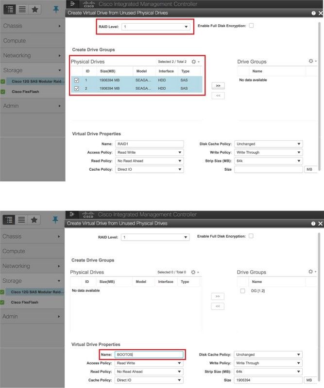
Step 6. Select the VD and configure Set as Boot Drive, as shown in the image.

Step 7. In order to enable IPMI over LAN, navigate to Admin > Communication Services > Communication Services, as shown in the image.

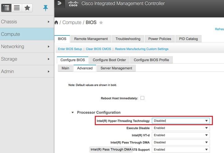
Step 8. In order to disable hyperthreading, navigate to Compute > BIOS > Configure BIOS > Advanced > Processor Configuration.
Note: The image shown here and the configuration steps mentioned in this section are with reference to the firmware version 3.0(3e) and there might be slight variations if you work on other versions.
Add the New Compute Node to the Overcloud
The steps mentioned in this section are common irrespective of the VM hosted by the compute node.
Step 1. Add Compute server with a different index
Create an add_node.json file with only the details of the new compute server to be added. Ensure that the index number for the new compute server has not been used before. Typically, increment the next highest compute value.
Example: Highest prior was compute-17, therefore, created compute-18 in case of 2-vnf system.
Note: Be mindful of the json format.
[stack@director ~]$ cat add_node.json
{
    "nodes":[
        {
            "mac":[
                "<MAC_ADDRESS>"
            ],
            "capabilities": "node:compute-18,boot_option:local",
            "cpu":"24",
            "memory":"256000",
            "disk":"3000",
            "arch":"x86_64",
            "pm_type":"pxe_ipmitool",
            "pm_user":"admin",
            "pm_password":"<PASSWORD>",
            "pm_addr":"192.100.0.5"
        }
    ]
}
Step 2. Import the json file.
[stack@director ~]$ openstack baremetal import --json add_node.json
Started Mistral Workflow. Execution ID: 78f3b22c-5c11-4d08-a00f-8553b09f497d
Successfully registered node UUID 7eddfa87-6ae6-4308-b1d2-78c98689a56e
Started Mistral Workflow. Execution ID: 33a68c16-c6fd-4f2a-9df9-926545f2127e
Successfully set all nodes to available.
Step 3. Run node introspection with the use of the UUID noted from the previous step.
[stack@director ~]$ openstack baremetal node manage 7eddfa87-6ae6-4308-b1d2-78c98689a56e
[stack@director ~]$ ironic node-list |grep 7eddfa87
| 7eddfa87-6ae6-4308-b1d2-78c98689a56e | None | None                                 | power off   | manageable         | False       |

[stack@director ~]$ openstack overcloud node introspect 7eddfa87-6ae6-4308-b1d2-78c98689a56e --provide
Started Mistral Workflow. Execution ID: e320298a-6562-42e3-8ba6-5ce6d8524e5c
Waiting for introspection to finish...
Successfully introspected all nodes.
Introspection completed.
Started Mistral Workflow. Execution ID: c4a90d7b-ebf2-4fcb-96bf-e3168aa69dc9
Successfully set all nodes to available.

[stack@director ~]$ ironic node-list |grep available
| 7eddfa87-6ae6-4308-b1d2-78c98689a56e | None | None                                 | power off   | available          | False       |
Step 4. Run deploy.sh script that was previously used to deploy the stack, in order to add the new computenode to the overcloud stack:
[stack@director ~]$ ./deploy.sh
++ openstack overcloud deploy --templates -r /home/stack/custom-templates/custom-roles.yaml -e /usr/share/openstack-tripleo-heat-templates/environments/puppet-pacemaker.yaml -e /usr/share/openstack-tripleo-heat-templates/environments/network-isolation.yaml -e /usr/share/openstack-tripleo-heat-templates/environments/storage-environment.yaml -e /usr/share/openstack-tripleo-heat-templates/environments/neutron-sriov.yaml -e /home/stack/custom-templates/network.yaml -e /home/stack/custom-templates/ceph.yaml -e /home/stack/custom-templates/compute.yaml -e /home/stack/custom-templates/layout.yaml --stack ADN-ultram --debug --log-file overcloudDeploy_11_06_17__16_39_26.log --ntp-server 172.24.167.109 --neutron-flat-networks phys_pcie1_0,phys_pcie1_1,phys_pcie4_0,phys_pcie4_1 --neutron-network-vlan-ranges datacentre:1001:1050 --neutron-disable-tunneling --verbose --timeout 180
…
Starting new HTTP connection (1): 192.200.0.1
"POST /v2/action_executions HTTP/1.1" 201 1695
HTTP POST http://192.200.0.1:8989/v2/action_executions 201
Overcloud Endpoint: http://10.1.2.5:5000/v2.0
Overcloud Deployed
clean_up DeployOvercloud:
END return value: 0

real   38m38.971s
user   0m3.605s
sys    0m0.466s
Step 5. Wait for the openstack stack status to be Complete.
[stack@director ~]$  openstack stack list
+--------------------------------------+------------+-----------------+----------------------+----------------------+
| ID                                   | Stack Name | Stack Status    | Creation Time        | Updated Time         |
+--------------------------------------+------------+-----------------+----------------------+----------------------+
| 5df68458-095d-43bd-a8c4-033e68ba79a0 | ADN-ultram | UPDATE_COMPLETE | 2017-11-02T21:30:06Z | 2017-11-06T21:40:58Z |
+--------------------------------------+------------+-----------------+----------------------+----------------------+
Step 6. Check that new compute node is in the Active state.
[root@director ~]# nova list | grep pod2-stack-compute-4

| 5dbac94d-19b9-493e-a366-1e2e2e5e34c5 | pod2-stack-compute-4     | ACTIVE | -          | Running     | ctlplane=192.200.0.116 |
Restore the VMs
Recover an Instance through Snapshot
Recovery Process:
It is possible to redeploy the previous instance with the snapshot taken in previous steps.
Step 1 [OPTIONAL]. If there is no previous VMsnapshot available then connect to the OSPD node where the backup was sent and sftp the backup back to its original OSPD node. Through sftp root@x.x.x.x where x.x.x.x is the IP of the original OSPD. Save the snapshot file in /tmp directory.
Step 2. Connect to the OSPD node where the instance is re-deploy.

Source the environment variables with the following command:
# source /home/stack/pod1-stackrc-Core-CPAR
Step 3. To use the snapshot as an image is necessary to upload it to horizon as such. Use the next command to do so.
#glance image-create -- AAA-CPAR-Date-snapshot.qcow2 --container-format bare --disk-format qcow2 --name AAA-CPAR-Date-snapshot
The process can be seen in horizon.

Step 4. In the Horizon, navigate to Project > Instances and click on Launch Instance, as shown in the image.

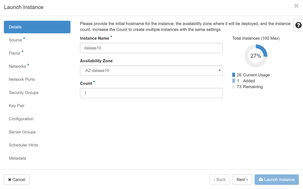
Step 5. Enter the Instance Name and choose the Availability Zone, as shown in the image.
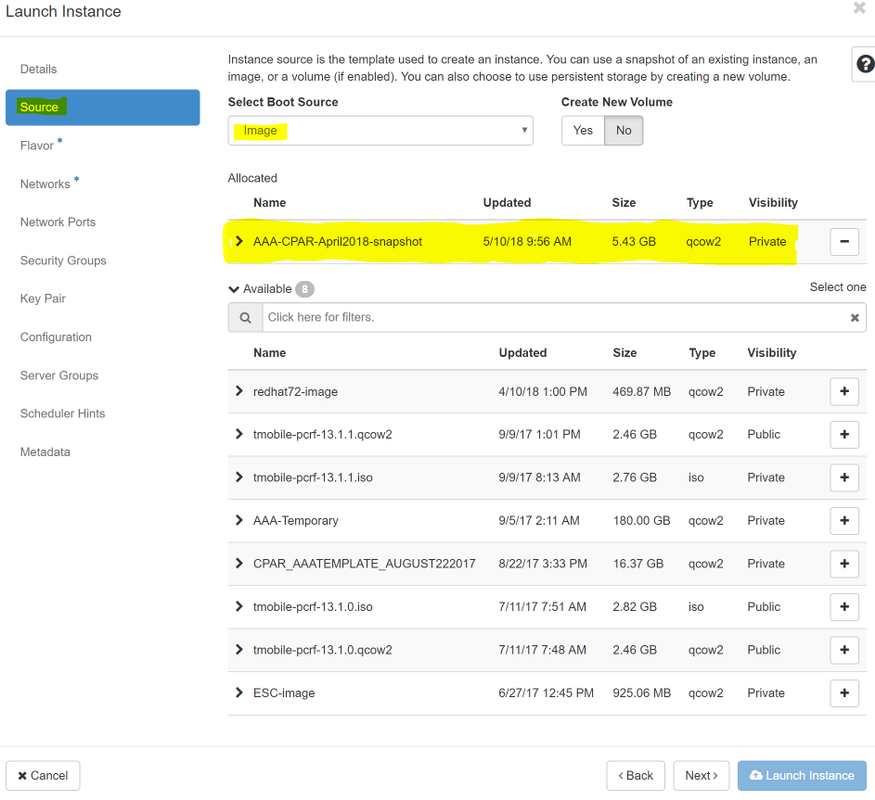
Step 6. In the Source tab, choose the image to create the instance. In the Select Boot Source menu select image, a list of images is shown here, choose the one that was previously uploaded as you click on + sign.
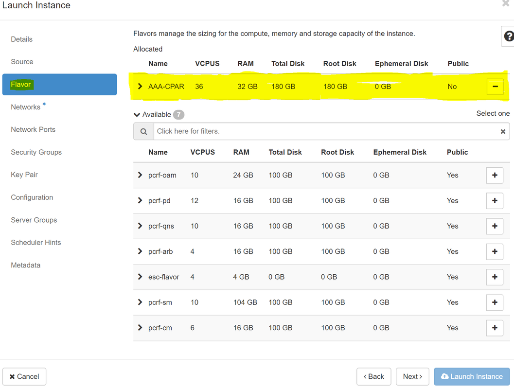
Step 7. In the Flavor tab, choose the AAA flavor as you click on + sign, as shown in the image.
Step 8. Now navigate to the Networks tab and choose the networks that the instance needs as you click on + sign. In this case, select diameter-soutable1, radius-routable1 and tb1-mgmt, as shown in the image.
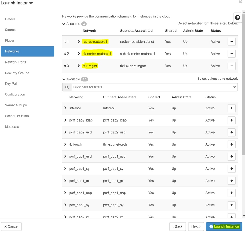
Step 9. Click on Launch instance to create it. The progress can be monitored in Horizon:

After a few minutes the instance will be completely deployed and ready for use.

Create and Assign a Floating IP Address
A floating IP address is a routable address, which means that it’s reachable from the outside of Ultra M/Openstack architecture, and it’s able to communicate with other nodes from the network.
Step 1. In the Horizon top menu, navigate to Admin > Floating IPs.
Step 2. Click on the button Allocate IP to Project.
Step 3. In the Allocate Floating IP window select the Pool from which the new floating IP belongs, the Project where it is going to be assigned, and the new Floating IP Address itself.
For example:
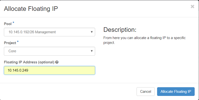
Step 4. Click on Allocate Floating IP button.
Step 5. In the Horizon top menu, navigate to Project > Instances.
Step 6. In the Action column, click on the arrow that points down in the Create Snapshot button, a menu should be displayed. Select Associate Floating IP option.
Step 7. Select the corresponding floating IP address intended to be used in the IP Address field, and choose the corresponding management interface (eth0) from the new instance where this floating IP is going to be assigned in the Port to be associated. Please refer to the next image as an example of this procedure.
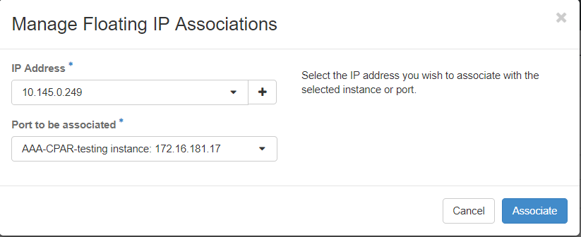
Step 8. Click on Associate.
Enable SSH
Step 1. In the Horizon top menu, navigate to Project > Instances.
Step 2. Click on the name of the instance/VM that was created in section Lunch a new instance.
Step 3. Click on Console tab. This displays the CLI of the VM.
Step 4. Once the CLI is displayed, enter the proper login credentials:
Username: root
Password: cisco123
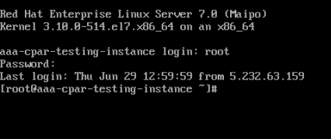
Step 5. In the CLI enter the command vi /etc/ssh/sshd_config to edit ssh configuration.
Step 6. Once the ssh configuration file is open, press I to edit the file. Then look for the section showed below and change the first line from PasswordAuthentication no to PasswordAuthentication yes.

Step 7. Press ESC and enter :wq! to save sshd_config file changes.
Step 8. Run the command service sshd restart.

Step 9. In order to test SSH configuration changes have been correctly applied, open any SSH client and try to establish a remote secure connection using the floating IP assigned to the instance (i.e. 10.145.0.249) and the user root.

Establish an SSH Session
Open an SSH session with the IP address of the corresponding VM/server where the application is installed.

CPAR Instance Start
Please follow the below steps, once the activity has been completed and CPAR services can be re-established in the Site that was shut down.
- In order to login back to Horizon, navigate to Project > Instance > Start Instance.
- Verify that the status of the instance is active and the power state is running:

Post-activity Health Check
Step 1. Execute the command /opt/CSCOar/bin/arstatus at OS level.
[root@wscaaa04 ~]# /opt/CSCOar/bin/arstatus
Cisco Prime AR RADIUS server running       (pid: 24834)
Cisco Prime AR Server Agent running        (pid: 24821)
Cisco Prime AR MCD lock manager running    (pid: 24824)
Cisco Prime AR MCD server running          (pid: 24833)
Cisco Prime AR GUI running                 (pid: 24836)
SNMP Master Agent running                (pid: 24835)
[root@wscaaa04 ~]#
Step 2. Execute the command /opt/CSCOar/bin/aregcmd at OS level and enter the admin credentials. Verify that CPAR Health is 10 out of 10 and the exit CPAR CLI.
[root@aaa02 logs]# /opt/CSCOar/bin/aregcmd
Cisco Prime Access Registrar 7.3.0.1 Configuration Utility
Copyright (C) 1995-2017 by Cisco Systems, Inc.  All rights reserved.
Cluster:
User: admin
Passphrase:
Logging in to localhost
[ //localhost ]
      LicenseInfo = PAR-NG-TPS 7.2(100TPS:)

                  PAR-ADD-TPS 7.2(2000TPS:)

                  PAR-RDDR-TRX 7.2()

                  PAR-HSS 7.2()

    Radius/

    Administrators/
Server 'Radius' is Running, its health is 10 out of 10
--> exit
Step 3.Execute the command netstat | grep diameter and verify that all DRA connections are established.
The output mentioned below is for an environment where Diameter links are expected. If fewer links are displayed, this represents a disconnection from the DRA that needs to be analyzed.
[root@aa02 logs]# netstat | grep diameter
tcp         0            0 aaa02.aaa.epc.:77 mp1.dra01.d:diameter ESTABLISHED
tcp         0            0 aaa02.aaa.epc.:36 tsa6.dra01:diameter ESTABLISHED
tcp         0            0 aaa02.aaa.epc.:47 mp2.dra01.d:diameter ESTABLISHED
tcp         0            0 aaa02.aaa.epc.:07 tsa5.dra01:diameter ESTABLISHED
tcp         0            0 aaa02.aaa.epc.:08 np2.dra01.d:diameter ESTABLISHED
Step 4. Check that the TPS log shows requests being processed by CPAR. The values highlighted represent the TPS and those are the ones we need to pay attention to.
The value of TPS should not exceed 1500.
[root@wscaaa04 ~]# tail -f /opt/CSCOar/logs/tps-11-21-2017.csv
11-21-2017,23:57:35,263,0
11-21-2017,23:57:50,237,0
11-21-2017,23:58:05,237,0
11-21-2017,23:58:20,257,0
11-21-2017,23:58:35,254,0
11-21-2017,23:58:50,248,0
11-21-2017,23:59:05,272,0
11-21-2017,23:59:20,243,0
11-21-2017,23:59:35,244,0
11-21-2017,23:59:50,233,0
Step 5. Look for any “error” or “alarm” messages in name_radius_1_log
[root@aaa02 logs]# grep -E "error|alarm" name_radius_1_log
Step 6.Verify the amount of memory that the CPAR process is, with this command:
top | grep radius
[root@sfraaa02 ~]# top | grep radius
27008 root      20   0 20.228g 2.413g  11408 S 128.3  7.7   1165:41 radius
This highlighted value should be lower than: 7Gb, which is the maximum allowed at an application level.
Contributed by Cisco Engineers
- Karthikeyan DachanamoorthyCisco Advance Services
- Harshita BhardwajCisco Advance Services
Contact Cisco
- Open a Support Case

- (Requires a Cisco Service Contract)
 Feedback