Cable Modem Basic Install with Cisco Network Registrar
Available Languages
Download Options
Bias-Free Language
The documentation set for this product strives to use bias-free language. For the purposes of this documentation set, bias-free is defined as language that does not imply discrimination based on age, disability, gender, racial identity, ethnic identity, sexual orientation, socioeconomic status, and intersectionality. Exceptions may be present in the documentation due to language that is hardcoded in the user interfaces of the product software, language used based on RFP documentation, or language that is used by a referenced third-party product. Learn more about how Cisco is using Inclusive Language.
Contents
Introduction
The purpose of this tech note is to provide a complete setup guide for a cable modem (CM) network in a lab environment. This setup can be used as a first step before deployment to a customer network. It is important to note that a trouble-free setup in the lab does not necessarily mean a trouble-free setup in a customer’s network. In a controlled lab environment, noise may not be an issue; while in real life, it can be quite the opposite. However, this procedure can be used to rule out issues that arise from the Cisco IOS® Software Release, the configuration, the hardware, and Radio Frequency (RF).
Prerequisites
Requirements
There are no specific requirements for this document.
Components Used
The information in this document was created from the devices in a specific lab environment. All of the devices used in this document started with a cleared (default) configuration. If your network is live, make sure that you understand the potential impact of any command.
Conventions
For more information on document conventions, refer to the Cisco Technical Tips Conventions.
Lab Topology
Figure 1 – Lab Network Setup 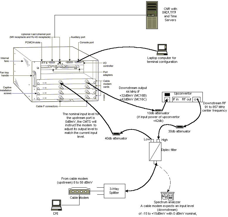
In this diagram, there is a Cable Modem Termination System (CMTS) that consists of these components:
-
uBR7246 that runs Cisco IOS Software Release 12.1(2)T with MC16C Modem Cards
-
CM uBR904 that runs Cisco IOS Software Release version 12.0(7)T
-
Upconverter
-
Diplex Filter to separate high frequency from low frequencies
-
Cisco Network Registrar (CNR) version 3.5(3)
-
Three-way Splitter
-
Customer Premises Equipment (CPE) which, in this case, is a laptop
Note: The RF setup in that diagram can be used as a starting reference point; however, this might change once you deploy it at a customer site. RF measurements are beyond the scope of this document; refer to Connecting the Cisco uBR7200 Series Router to the Cable Headend for proper RF setup and measurements.
Assumptions
-
The upconverter is already installed and configured properly. Refer to the vendor’s documentation for setup. Remember that if you are using a GI upconverter, it should be set at 1.75 MHz lower than the center frequency of the NTSC channel in question. (See Obtain Power Measurements of a DOCSIS Downstream Signal Using a Spectrum Analyzer.)
-
There is a properly configured CPE that sits behind the CM, specifically to obtain an IP address via the DHCP server.
-
The CNR is used as the DHCP and TFTP servers, with the same IP address: 172.17.110.136.
-
The Time of Day (ToD) server software is running on the same NT server as CNR.
The sections in this document explain the steps that are needed to configure these components:
-
Cisco Network Registrar (CNR)
-
Data-over-Cable Service Interface Specification (DOCSIS) configuration file
-
Cable Modem Termination System (CMTS)
-
Cable Modem (CM)
Network Diagram
Figure 2 – Network Diagram with the IP Addresses and Names Used in this Tech Note 
Cisco Network Registrar Configuration
Follow this procedure to configure the CNR:
-
Launch CNR from the Start menu.
-
On the menu bar, click the Add tab to add a new cluster.
-
Enter the cluster name.
In this case, an IP address is used as the name.
-
Check the Connect to this cluster once added checkbox.
-
Click OK.

-
-
When you are prompted for the Username and Password, use admin and changeme.
Figure 4 – Username and Password Window in CNR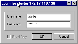
-
Click OK.
A window appears that is similar to Figure 5, which contains the names or IP addresses of the configured clusters.
Figure 5 – Server Manager Window in CNR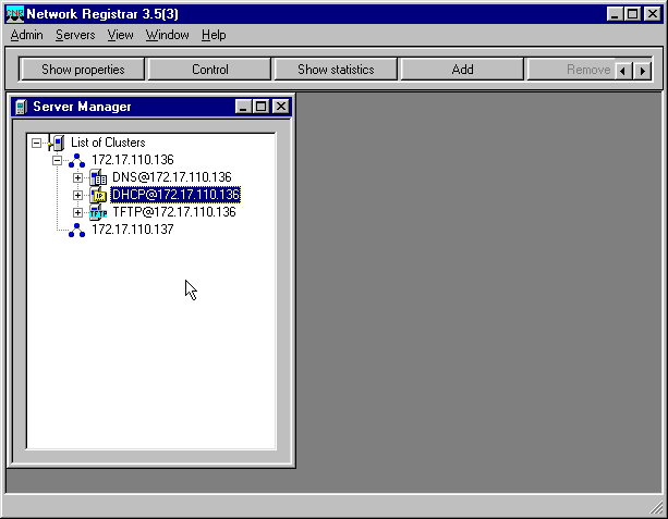
-
Double-click DHCP@172.17.110.136, to bring up the DHCP@172.17.110.136 Properties window.
-
Click the Policies tab and then click New, to create a new policy.
Figure 6 – Adding a Policy Called “Cable Modems” and Copying the Attributes from the “default” Policy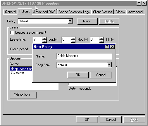
-
Type in the name of the policy.
In this example, the name is Cable Modems.
-
If this is a new policy, set the Copy from field to default.
-
Click OK.
-
Click Edit options, to specify DHCP options.
For the policy called Cable Modems, add the following options (see Figure 7):
-
dhcp-lease-time is active by default and set to 604800 seconds, which is the number of seconds in one week.
-
routers is the IP address of the CMTS cable interface, in this case 10.1.1.10. See Configuring the Headend (CMTS).
-
time-offset of the CM from Universal Coordinated Time (UTC); this is used by the CM to calculate the local time, in order to time-stamp error logs. See How to Calculate the Hexadecimal Value for DHCP Option 2 (time offset)).
-
time-servers IP address for the ToD server, which is 172.17.110.136.
-
packet-siaddr is the IP address of TFTP server, which is 172.17.110.136.
-
packet-file-name is the DOCSIS configuration file configured with the DOCSIS CPE Configurator. This file should reside in the tftpboot directory of the TFTP server.
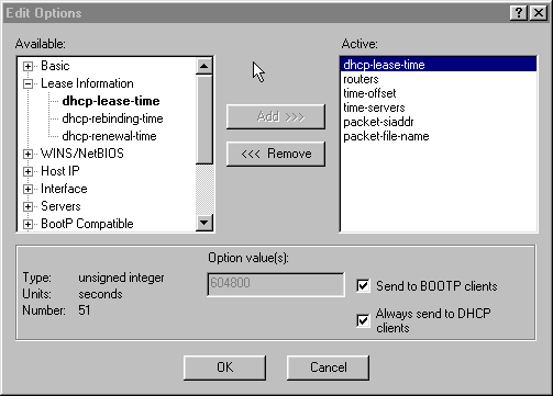
Note: Ensure that you check the Send to BOOTP clients checkbox, if you have BOOTP clients. It is also highly recommended that you check the Always send to DHCP clients checkbox.
-
-
Create another policy associated with the CPEs behind the CM, like laptops, and so forth.
In this example, the name of the policy is Cable Modem Clients.
Follow the same procedure as was used for the Cable Modems policy except, this time, set the Copy from field to the Cable Modems policy instead of to the default policy.
Figure 8 – Adding a Policy Called “Cable Modem Clients” and Copying the Attributes from the Existing Policy Named “Cable Modems”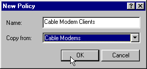
-
Click OK.
-
Click the Edit option button, to select the active options.
-
For the CPE policy, remove all options from the Active list except the dhcp-lease-time and the routers options.
To do so, select the property to delete in the Active list and click the Remove button.
-
Change the IP address for the routers option to 192.168.1.1, which is the secondary IP address configured on the CMTS router.
See Configuring the Headend (CMTS).
Figure 9 – Adding the IP Address for the routers Attribute, which is the Secondary IP Address Configured in the Cable Interface to which this Policy Applies in the CMTS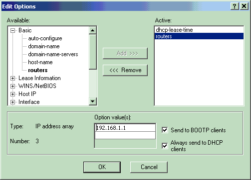
Note: This example uses a private IP address as the secondary address on the CMTS and in the Cable Modems Client policy. In a production environment, CPE devices should use a public IP address, to be able to access the Internet (unless Network Address Translation [NAT] is used).
-
Create scopes to associate with the Cable Modems and Cable Modem Clients policies.
-
To make a new scope, click on DHCP@172.17.110.136 in the main menu, and then click the Add tab.
This will allow you to add a new scope.
-
Enter the name of the new scope and then select the appropriate policy.
In this example, the scope for the Cable Modems is set to use the IP addresses range from 10.1.1.20 to 10.1.1.30.
Figure 10 – Scope for the Cable Modems called “Cable Modems”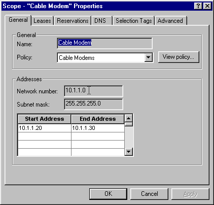
-
Repeat Steps 16a and 16b for the Cable Modem Clients scope.
In this case, the private IP address range from 192.168.1.20 to 192.168.1.30 is used.
Figure 11 – Scope for CPE Equipment Behind the Cable Modems called “Cable Modem Clients”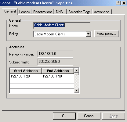
-
The scope used for the CPE devices requires additional configuration.
-
Once you have created the Cable Modem Clients scope, you need to double-click the scope to open the dialog box that is shown in Figure 12.
Figure 12 – Cable Modem Clients Scope Window
-
Click the Advanced tab, in order to relate the secondary scope to the primary scope.
-
Check the Make this scope a secondary checkbox.
-
Once the drop-down list shows a blank value, select the appropriate primary scope.
In this example, the Cable Modems scope is selected.
Figure 13 – Making the “Cable Modem Clients” Scope Secondary and Relating It to the Primary Scope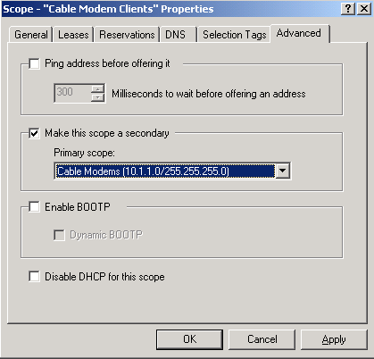
-
-
-
Finally, you need to restart your DHCP server so that your changes can take place.
In the main menu, select DHCP@172.17.110.136 and click the Control tab at the top, to get the dialog box shown in Figure 14. This dialog box allows you to reload the DHCP server.
Figure 14 – Reload Window to Commit Changes in CNR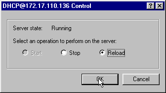
DOCSIS Configuration File
The next step that is required to setup a Cable Network is to compose the configuration file. For a cable modem to come online, it needs to download its configuration file via TFTP from a DHCP server. In this document’s example, CNR is used to provide both TFTP and DHCP servers. Refer to DHCP and the DOCSIS Configuration File for Cable Modems (DOCSIS 1.0) for more information on the minimum requirements to setup the configuration file. The file is set up with the DOCSIS CPE Configurator. In the On the CM (uBR904) section of this document, the DOCSIS configuration file that is used is called platinum.cm.
Note: Once the configuration file is created, ensure that it is copied to the TFTP server. In the case of CNR’s TFTP server, you also must ensure that the TFTP server is started:
-
Select TFTP@172.17.110.136 and then click the Control tab.
This brings up the TFTP@172.17.110.136 Control dialog box, where the server can be started.
-
The TFTP server functionality is off by default. To make the TFTP server start automatically at bootup, start NRCMD (the command line interface for CNR) and issue these commands:
server tftp set start-on-reboot=enabled

save
Configuring the Headend (CMTS)
This is a basic configuration for the CMTS (the uBR7246):
Current configuration:
!
version 12.1
service timestamps debug uptime
service timestamps log uptime
no service password-encryption
!
hostname Sydney
!
boot system flash ubr7200-ik1s-mz_121-2_T.bin
no logging buffered
enable password <deleted>
!
no cable qos permission create

!--- Default.

no cable qos permission update

!--- Default.

cable qos permission modems

!--- Default.

!
!
!
ip subnet-zero
no ip domain-lookup
!
!
interface FastEthernet0/0
 no ip address
 shutdown
 half-duplex
!
interface Ethernet1/0
 ip address 172.17.110.139 255.255.255.224

!--- The IP address of the interface in the same LAN segment as CNR.

!
interface Ethernet1/1
 no ip address
 shutdown
!
interface Ethernet1/2
 no ip address
 shutdown
!
interface Ethernet1/3
 no ip address
 shutdown
!
interface Ethernet1/4
 no ip address
 shutdown
!
interface Ethernet1/5
 no ip address
 shutdown
!
interface Ethernet1/6
 no ip address
 shutdown
!
interface Ethernet1/7
 no ip address
 shutdown
!
 interface Cable2/0
 ip address 192.168.1.1 255.255.255.0 secondary

!--- The secondary IP address is used for the CPE’s scope in CNR.

 ip address 10.1.1.10 255.255.255.0

!--- The primary IP address is used for the CM’s scope in CNR.

 no keepalive
 cable downstream annex B

!--- Default for DOCSIS-compliant cable plants. For EuroDOCSIS, use annex A.

 cable downstream modulation 64qam

!--- Default.

 cable downstream interleave-depth 32

!--- Default.

 cable downstream frequency 451250000

!--- Cosmetic except for the uBR7100. This line has no effect !--- on Upconverter Frequency. Used as a reminder of the frequency !--- that is used in the Unconverter.

 cable upstream 0 frequency 28000000

!--- Upstream Frequency configuration. This is chosen after a careful !--- analysis on the noise levels of the return path.

 cable upstream 0 power-level 0
 no cable upstream 0 shutdown

!--- Enables the upstream 0 port.

 cable upstream 1 shutdown
 cable upstream 2 shutdown
 cable upstream 3 shutdown
 cable upstream 4 shutdown
 cable upstream 5 shutdown
 cable dhcp-giaddr policy

!--- Modifies the GIADDR field of DHCPDISCOVER and DHCPREQUEST packets.

 cable helper-address 172.17.110.136

!--- Specifies a destination IP address for UDP-broadcast DHCP packets.

!
interface Cable3/0
 no ip address
 no keepalive
 shutdown
 cable downstream annex B
 cable downstream modulation 64qam
 cable downstream interleave-depth 32
 cable upstream 0 shutdown
 cable upstream 1 shutdown
 cable upstream 2 shutdown
 cable upstream 3 shutdown
 cable upstream 4 shutdown
 cable upstream 5 shutdown
!
ip classless
ip route 0.0.0.0 0.0.0.0 172.17.110.129
no ip http server
!
line con 0
 exec-timeout 0 0
 transport input none
line aux 0
line vty 0
 exec-timeout 0 0
  transport input none
line aux 0
line vty 0
 exec-timeout 0 0
 password cisco
 login
line vty 1 4
 password cisco
 login
!
end
Configuring the CM
Typically, a cable modem does not require any user configuration for it to come online (aside from factory defaults). This applies only if the CM is to be used as a bridge. This is an example of a uBR cable modem configuration that is being obtained automatically, after the CM comes online:
version 12.0
no service pad
service timestamps debug uptime
service timestamps log uptime
no service password-encryption
!
hostname Router
!
clock timezone - 0
ip subnet-zero
no ip routing
!
!
interface Ethernet0
 ip address 10.1.1.25 255.255.255.0
 no ip directed-broadcast
 no ip route-cache
 bridge-group 59
 bridge-group 59 spanning-disabled
!
interface cable-modem0
 ip address negotiated
 no ip directed-broadcast
 no ip route-cache
 cable-modem downstream saved channel 453000000 20 1
 cable-modem mac-timer t2 40000
 bridge-group 59
 bridge-group 59 spanning-disabled
!
ip default-gateway 10.1.1.10
ip classless
no ip http server
!
!
line con 0
 transport input none
line vty 0 4
!
end
Verification and Troubleshooting
This section describes commands that can be used to verify correct operation of the Cable Network.
On the CMTS (uBR7246)
Ensure that the cable modems are online:
Sydney# show cable modem

Interface   Prim Online     Timing Rec    QoS CPE IP address      MAC address
            Sid  State      Offset Power
Cable2/0/U0 2    online     2290   -0.25  6   1   10.1.1.25       0050.7366.2223
If the cable modems are stuck in init(d) state, then there is no connectivity between the CMTS cable’s interface and the DHCP Server.
Ensure that you can issue an extended ping from the cable interface of the CMTS:
Sydney# ping ip

Target IP address: 172.17.110.136
Repeat count [5]:
Datagram size [100]:
Timeout in seconds [2]:
Extended commands [n]: y
Source address or interface: 10.1.1.10
Type of service [0]:
Set DF bit in IP header? [no]:
Validate reply data? [no]:
Data pattern [0xABCD]:
Loose, Strict, Record, Timestamp, Verbose[none]:
Sweep range of sizes [n]:
Type escape sequence to abort.
Sending 5, 100-byte ICMP Echos to 172.17.110.136, timeout is 2 seconds:
!!!!!
Success rate is 100 percent (5/5), round-trip min/avg/max = 8/12/24 ms
If the ping is not successful, check the IP routing. Also, ensure that the NT server that is running CNR has the correct default gateway or route back to the CMTS. You can also issue a ping from CNR.
Another command that can be used on the CMTS to verify cable modem and CPE connectivity is show interface cable 2/0 modem 0:
Sydney# show interfaces cable 2/0 modem 0

SID   Priv bits  Type      State     IP address    method    MAC address
2     00         host      unknown   192.168.1.20  dhcp      0010.a4e6.d04d

!--- A laptop that is obtaining an IP address.

2     00         modem     up        10.1.1.25     dhcp      0050.7366.2223

!--- The cable modem.
On the CM (uBR904)
You can also check connectivity on the cable modem side. Issue the show ip interface brief command and check that the interfaces are up/up:
Router# show ip interface brief

Interface                  IP-Address      OK? Method Status         Protocol
Ethernet0                  10.1.1.25       YES unset  up             up
cable-modem0               10.1.1.25       YES unset  up             up

Router# show controllers cable-modem 0

BCM Cable interface 0:
CM unit 0, idb 0x2010AC, ds 0x86213E0, regaddr = 0x800000, reset_mask 0x80
station address 0050.7366.2223  default station address 0050.7366.2223
PLD VERSION: 32
MAC State is maintenance_state, Prev States = 15
MAC mcfilter 01E02F00  data mcfilter 01000000
MAC extended header ON
DS: BCM 3116 Receiver: Chip id = 2
US: BCM 3037 Transmitter: Chip id = 30AC
Tuner: status=0x00
Rx: tuner_freq 453000000, symbol_rate 5055880, local_freq 11520000
    snr_estimate 35210, ber_estimate 0, lock_threshold 26000
    QAM in lock, FEC in lock, qam_mode QAM_64
Tx: TX_freq 27984000, power_level 0x30 (24.0 dBmV), symbol_rate 8
    (1280000 sym/sec)
DHCP: TFTP server = 172.17.110.136, TOD server = 172.17.110.136
      Security server = 0.0.0.0, Timezone Offest = 0
      Config filename = platinum.cm
buffer size 1600

RX data PDU ring with 32 entries at 0x202130
   rx_head = 0x202168 (7), rx_p = 0x8621418 (7)

RX MAC message ring with 8 entries at 0x202270
  rx_head_mac = 0x2022A0 (6), rx_p_Mac = 0x86214BC (6)

TX BD ring with 8 entries at 0x2023A8, TX_count = 0
  TX_head = 0x2023C8 (4), head_txp = 0x8621548 (4)
  TX_tail = 0x2023C8 (4), tail_txp = 0x8621548 (4)

TX PD ring with 8 entries at 0x202428, TX_count = 0
  TX_head_pd = 0x202C28 (4)
  TX_tail_pd = 0x202C28 (4)

Global control and status:
  global_ctrl_status=0x00
interrupts:
  irq_pend=0x0008, irq_mask=0x00F7
You can also test IP connectivity. Ping the DHCP server from the CM:
Router# ping 172.17.110.136

Type escape sequence to abort.
Sending 5, 100-byte ICMP Echos to 172.17.110.136, timeout is 2 seconds:
!!!!!
Success rate is 100 percent (5/5), round-trip min/avg/max = 8/12/24 ms
uBR7246
Sydney# show version

Cisco Internetwork Operating System Software
IOS (tm) 7200 Software (UBR7200-IK1S-M),
     Version 12.1(2)T, RELEASE SOFTWARE (fc1)
Copyright (c) 1986-2000 by cisco Systems, Inc.
Compiled Tue 16-May-00 13:36 by ccai
Image text-base: 0x60008900, data-base: 0x613E8000
ROM: System Bootstrap,
     Version 11.1(10) [dschwart 10], RELEASE SOFTWARE (fc1)
BOOTFLASH: 7200 Software (UBR7200-BOOT-M),
     Version 12.0(10)SC, EARLY DEPLOYMENT RELEASE SOFTWARE (fc1)
Sydney uptime is 4 days, 40 minutes
System returned to ROM by reload
System image file is "slot0:ubr7200-ik1s-mz_121-2_T.bin"
cisco uBR7223 (NPE150) processor (revision B) with 57344K/8192K bytes of memory.
Processor board ID SAB0249006T
R4700 CPU at 150Mhz, Implementation 33, Rev 1.0, 512KB L2 Cache
3 slot midplane, Version 1.0
Last reset from power-on
Bridging software.
X.25 software, Version 3.0.0.
8 Ethernet/IEEE 802.3 interface(s)
1 FastEthernet/IEEE 802.3 interface(s)
2 Cable Modem network interface(s)
125K bytes of non-volatile configuration memory.
1024K bytes of packet SRAM memory.
20480K bytes of Flash PCMCIA card at slot 0 (Sector size 128K).
4096K bytes of Flash internal SIMM (Sector size 256K).
Configuration register is 0x2102
uBR904
Router# show version

Cisco Internetwork Operating System Software
IOS (TM) 900 Software (UBR900-K1OY556I-M),
     Version 12.0(7)T,  RELEASE SOFTWARE (fc2)
Copyright (c) 1986-1999 by cisco Systems, Inc.
Compiled Tue 07-Dec-99 02:01 by phanguye
Image text-base: 0x08004000, database: 0x0852E888


ROM: System Bootstrap,
     Version 11.2(19980518:195057), RELEASED SOFTWARE
ROM: 900 Software (UBR900-RBOOT-M),
     Version 11.3(7)NA, EARLY DEPLOYMENT RELEASE SOFTWARE (fc1)


Router uptime is 1 hour, 6 minutes
System returned to ROM by reload at 11:20:43 - Thu Oct 12 2001
System restarted at 11:21:53 - Thu Oct 12 2001
System image file is "flash:ubr900-k1oy556i-mz.120-7.T.bin"

cisco uBR900 CM (68360) processor (revision D) with 8192K bytes of memory.
Processor board ID FAA0315Q07M
Bridging software.
1 Ethernet/IEEE 802.3 interface(s)
1 Cable Modem network interface(s)
4096K bytes of processor board System flash (Read/Write)
2048K bytes of processor board Boot flash (Read/Write)


Configuration register is 0x2102
Related Information
Contact Cisco
- Open a Support Case

- (Requires a Cisco Service Contract)


 Feedback