Introduction
This document describes how to deploy disjoint Layer 2 networks upstream of the Fabric Interconnects while in Intersight Managed Mode.
Prerequisites
Requirements
Cisco recommends that you have knowledge of these topics:
- Basic understanding of Disjoint Layer 2 networks.
- Basic understanding of how to configure a UCS Domain in Intersight Managed Mode.
Components Used
- Intersight Managed Mode
- 6454 Fabric Interconnect
- 4.2.1g Firmware
The information in this document was created from the devices in a specific lab environment. All of the devices used in this document started with a cleared (default) configuration. If your network is live, ensure that you understand the potential impact of any command.
Background Information
Disjoint Layer 2 (DL2)
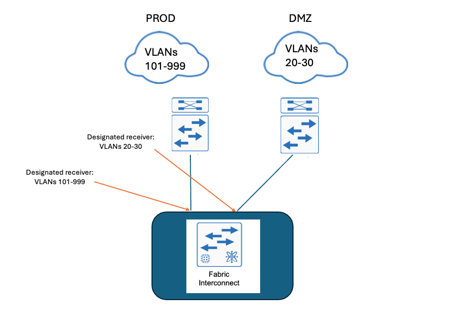
Disjoint layer-2 networks are required if you have two or more Ethernet clouds that never connect, but must be accessed by servers or virtual machines located in the same Cisco UCS domain.
They are also required in a multi-tenant environment if servers or virtual machines for more than one client are located in the same Cisco UCS domain and they need to access the L2 networks for both clients.
Network Diagram
Configure
Step 1. Create a VLAN Policy that includes all VLANs
Note: This includes our Production VLANs called PROD and our Demilitarized Zone VLANs called DMZ that are to be present in the environment.
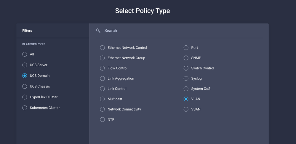
Navigate to Policies > Create Policy > VLAN.
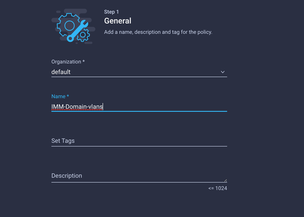
Create a Name and click Next.
Click Add VLANs.
Now when you add the VLAN or VLAN range for the PROD/DMZ network ensure to leave Auto Allow on Uplinks unchecked and add a Multicast policy. This ensures that these VLANs can be disjointed and assigned to specific ports or port channels later.
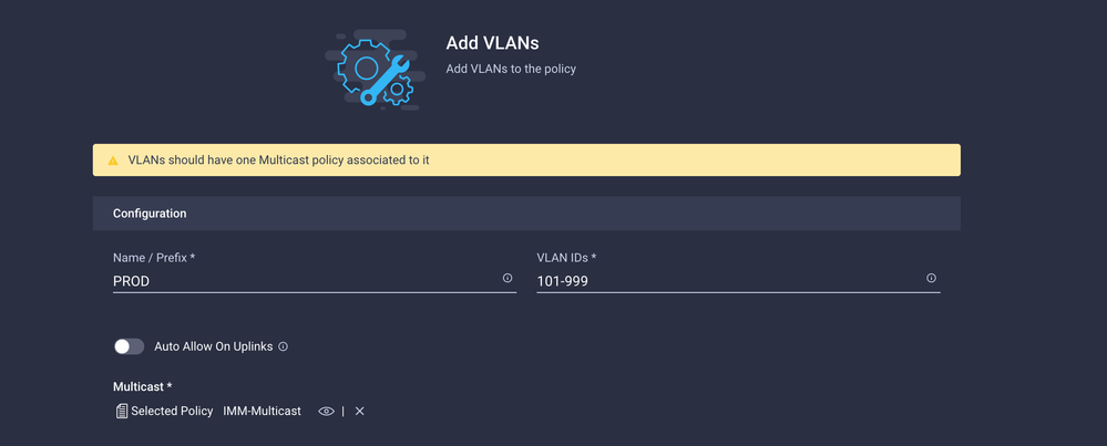
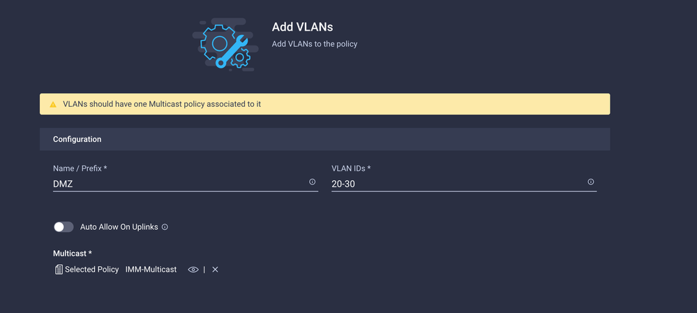
Once finished click Add to add the VLANs to the VLAN policy and click Create.
Step 2. Create a Ethernet Network Group Policy
This policy is used to assign the group of VLANs to specific Uplinks.
Navigate to Policies > Create Policy > Ethernet Network Group.
The first group of VLANs is for the Production Uplink.
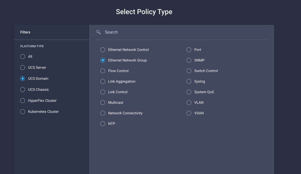 Create Eth Network Group
Create a Name and click Next.
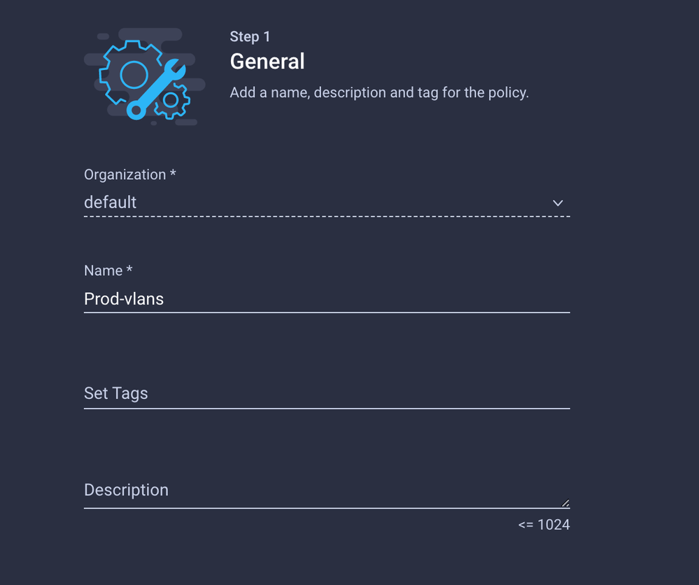 Name it Prod
 VLAN 101-999
The second group is for the DMZ Uplink.
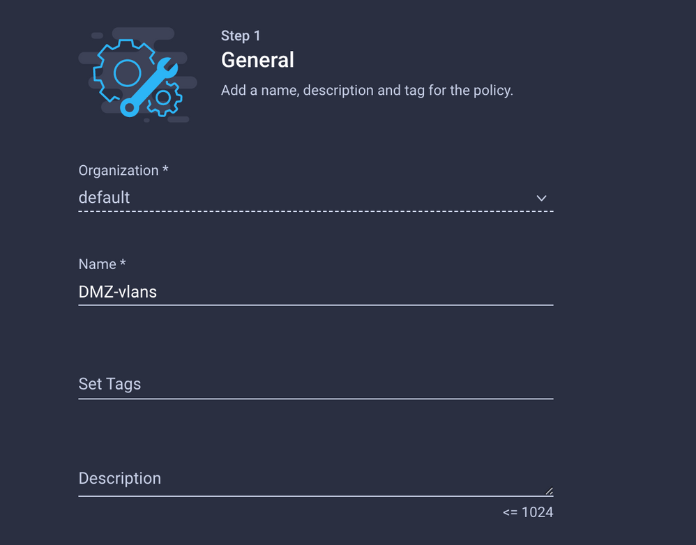
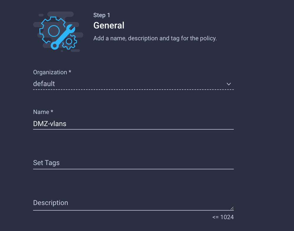 Name it DMZ
 VLAN 20-30
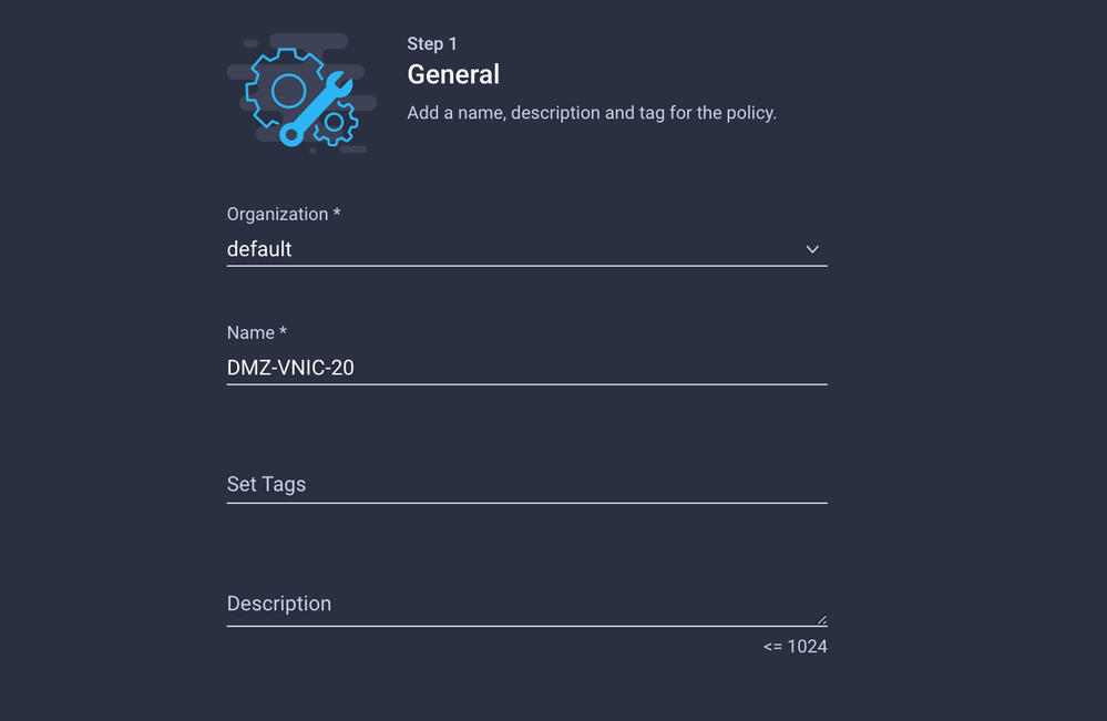
Step 3. Create a New Ethernet Network Group Policy for the Virtual NICs (Optional)
This step is optional because the Ethernet Network Group Policies that you have created in Step 2. can also be reused to assign them to the vNICs on a Service Profile.
Note: If the policies are reused then all the VLANs allowed on the Uplink are also allowed on the vNIC. If it is preferred to only allow a subset of VLANs then you need to create a separate policy and allow the preferred VLANs on the vNIC.
Navigate to Policies > Create Policy > Ethernet Network Group.
Create a Name and click Next.
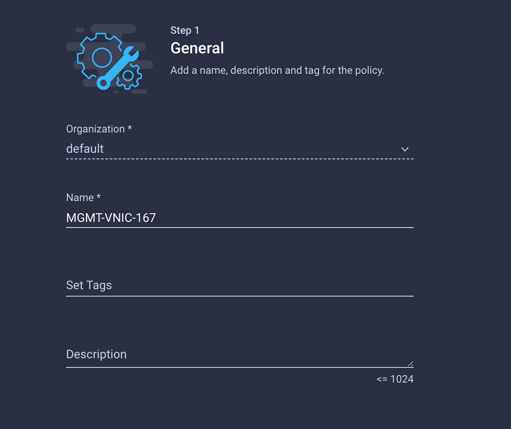

Create another Ethernet Network Group for the other DMZ VLAN.

Step 4. Create or Modify the Port Policy
Create a Port Policy or modify the one that already exists, then assign it to the Ethernet Network Group and to the appropriate Uplinks.
Navigate to the Policies tab > Create Policy > select Port > Create a Name > Next.
Select the Port or Port-channel and click Configure.
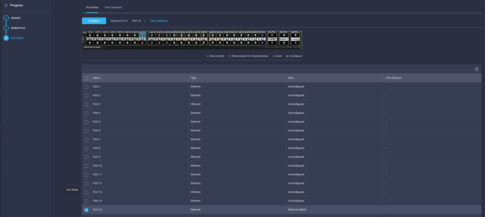
Assign the Ethernet Network Group created in Step 2.
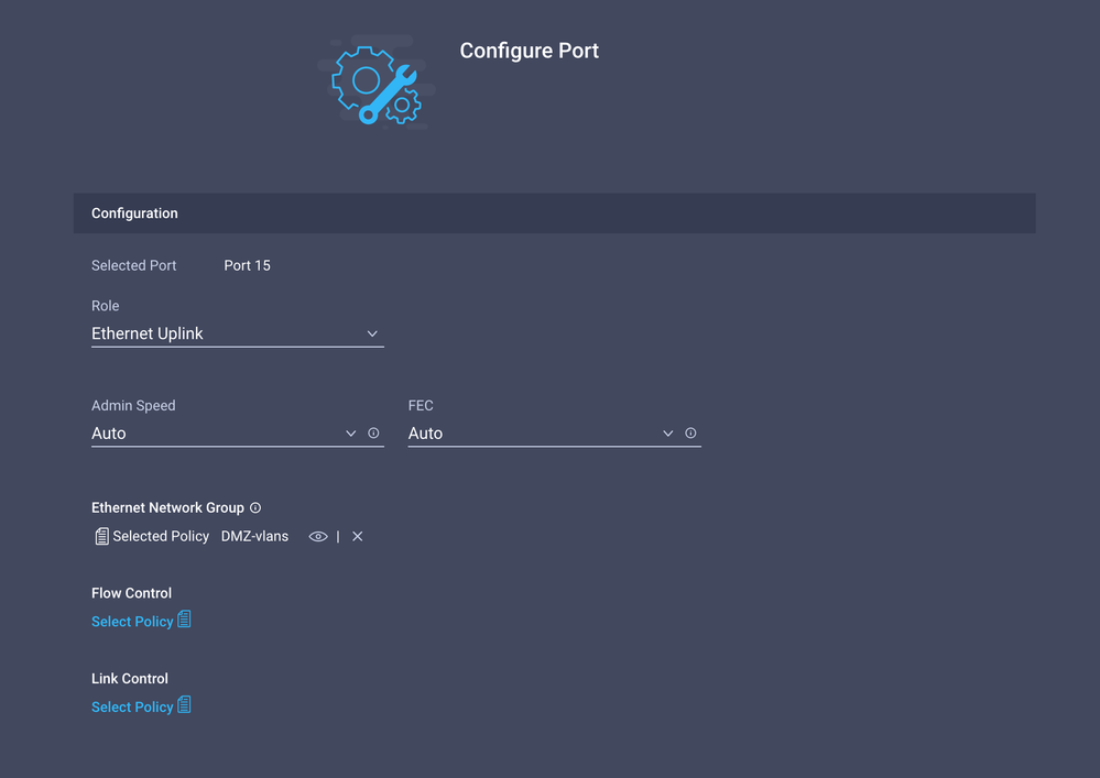
Repeat the same process for the other Uplink.
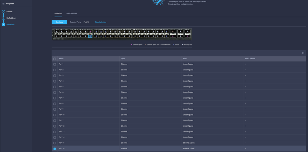
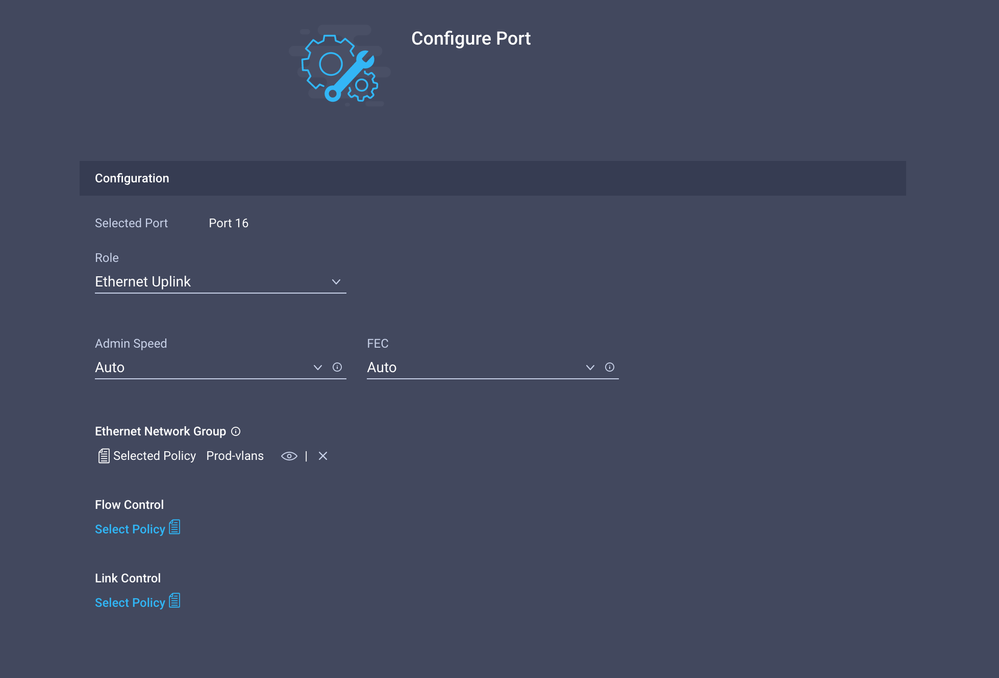
Step 5. Assign the VLAN Policy and the Port Policy to the Domain Profile
Navigate to Profiles > UCS Domain Profiles and select the appropriate Domain Profile.
Navigate to the Ports Configuration section.

Assign the Port Policy created in Step 4. to Fabric Interconnect A and B and proceed to the Summary section.
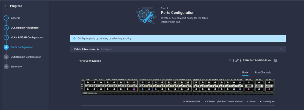
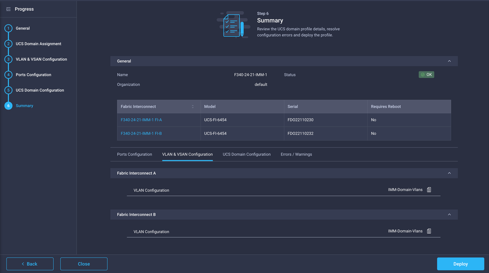
Review the configuration applied to the Domain Profile and click Deploy.
Step 6. Assign the Ethernet Group Policy to a LAN Connectivity Policy
You can use the LAN connectivity policy that already exists or create a new one.
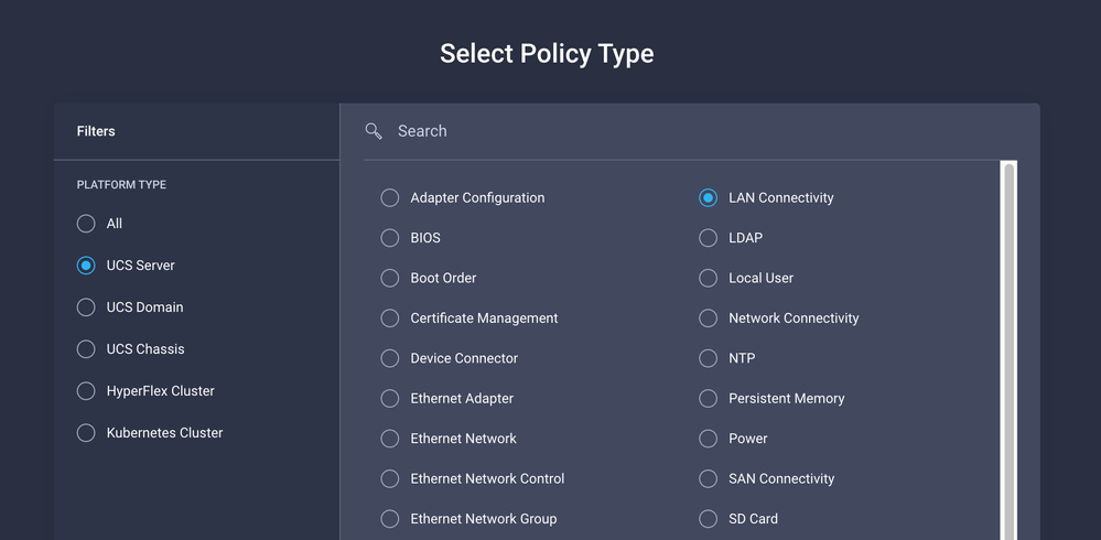
Navigate to Policies > Create Policy > Select LAN Connectivity.
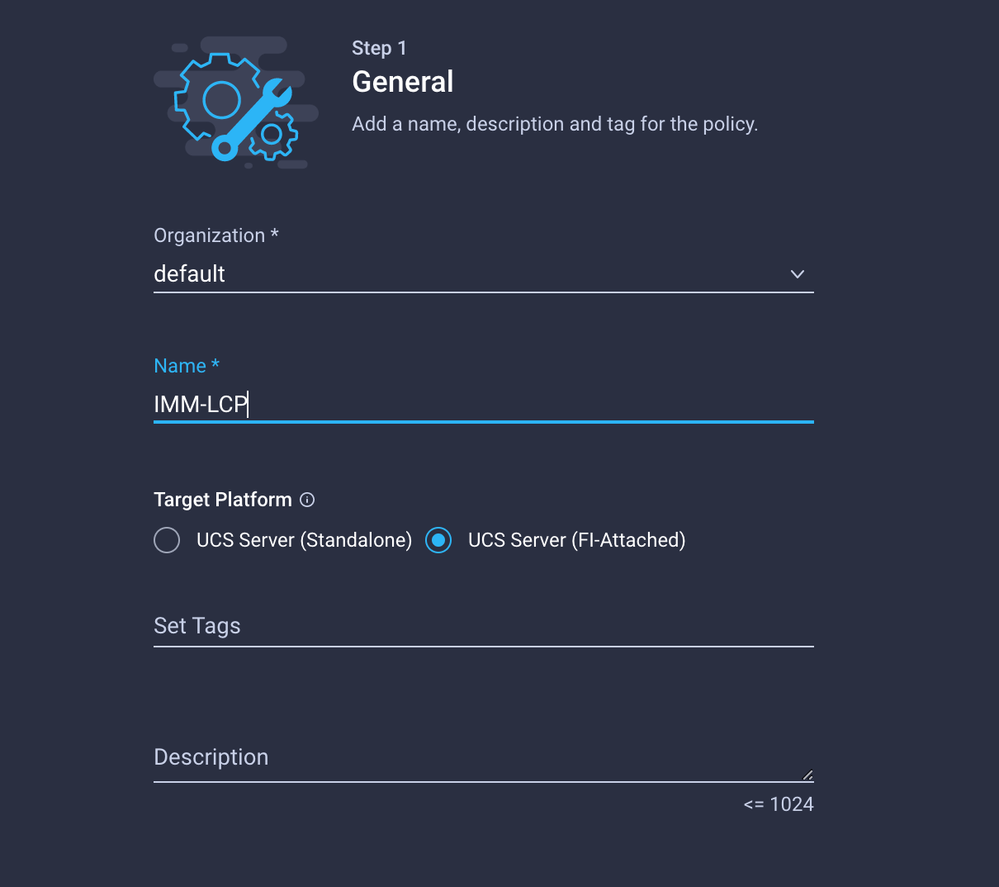
Enter a Name and click Next.
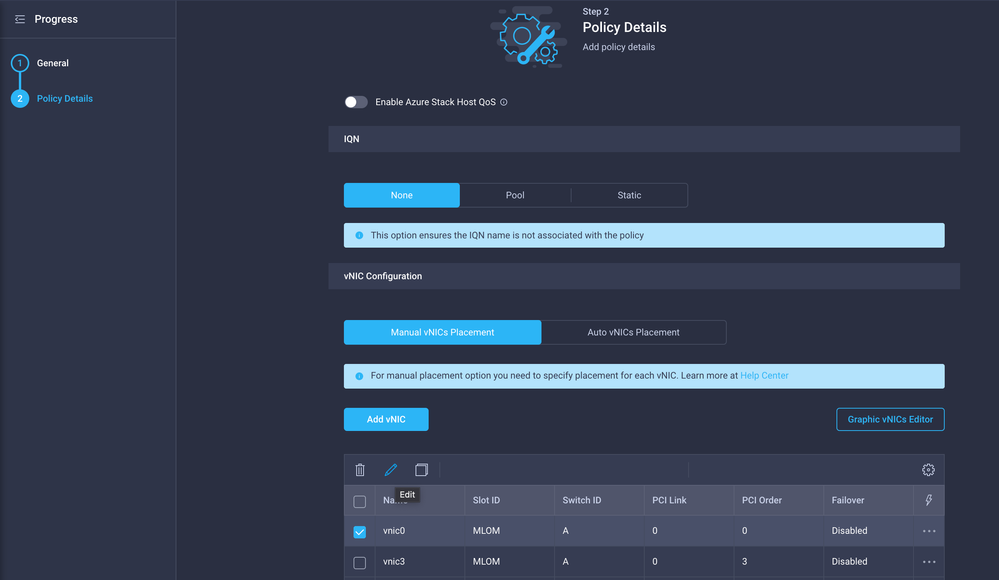
Configure the vNICs with the desired settings and include the Ethernet Network group that was created in Step 3. or, you can reuse the group created in Step 2.
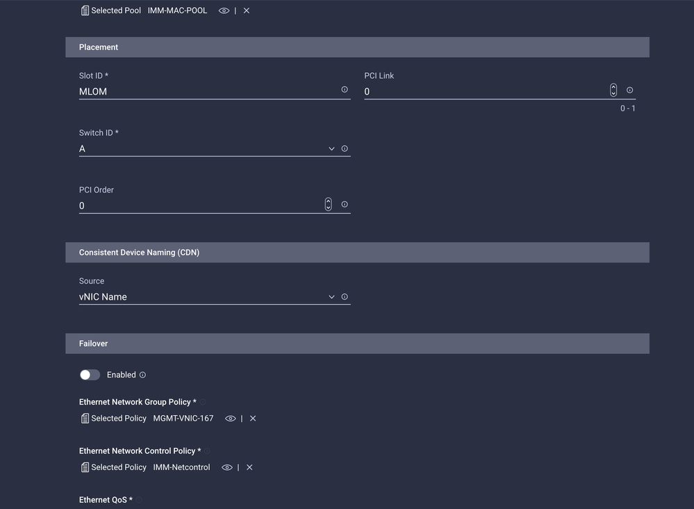
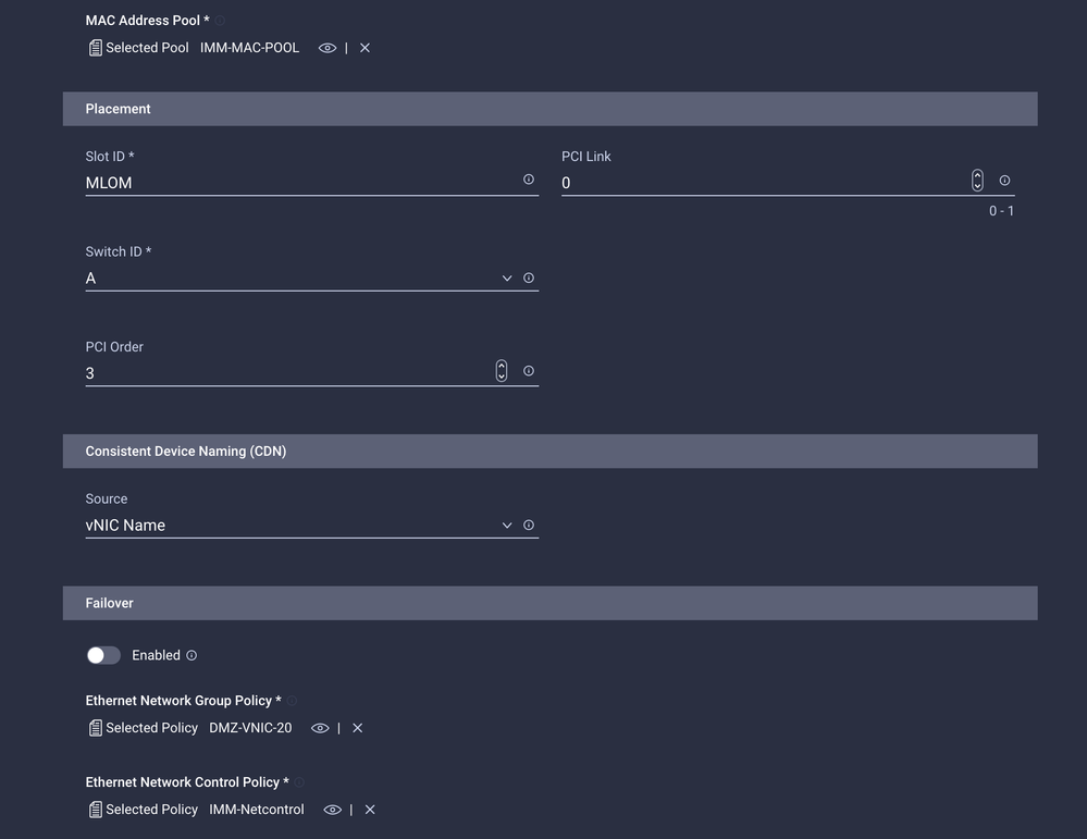
Assign the LAN Connectivity policy to a Service Profile and deploy.
Verify
Use this section to confirm that your configuration works properly.
Once the Domain profile has been deployed you can verify the VLANs are assigned to the appropriate Uplinks
Default (auto allow on all Uplinks) configuration:
LAB-IMM-B(nx-os)# show run interface ethernet 1/15
!Command: show running-config interface Ethernet1/15
!Running configuration last done at: Wed Mar  9 20:20:55 2022
!Time: Thu Mar 10 14:28:00 2022
version 9.3(5)I42(1g) Bios:version 05.42
interface Ethernet1/15
  description Uplink
  pinning border
  switchport mode trunk
  switchport trunk allowed vlan 1,101-999
  no shutdown

LAB-IMM-B(nx-os)# show run interface ethernet 1/16
!Command: show running-config interface Ethernet1/16
!Running configuration last done at: Wed Mar  9 20:20:55 2022
!Time: Thu Mar 10 14:28:06 2022
version 9.3(5)I42(1g) Bios:version 05.42
interface Ethernet1/16
  description Uplink
  pinning border
  switchport mode trunk
  switchport trunk allowed vlan 1,101-999
  no shutdown
After the assignment of the DMZ VLANs to port 1/15 and Production Vlans to port 1/16:
LAB-IMM-B(nx-os)# show run interface ethernet 1/15
!Command: show running-config interface Ethernet1/15
!Running configuration last done at: Thu Mar 10 18:13:38 2022
!Time: Thu Mar 10 18:21:54 2022
version 9.3(5)I42(1g) Bios:version 05.42
interface Ethernet1/15
  description Uplink
  pinning border
  switchport mode trunk
  switchport trunk allowed vlan 1,20-30
  no shutdown


LAB-IMM-B(nx-os)# show run interface ethernet 1/16
!Command: show running-config interface Ethernet1/16
!Running configuration last done at: Thu Mar 10 18:13:38 2022
!Time: Thu Mar 10 18:21:57 2022
version 9.3(5)I42(1g) Bios:version 05.42
interface Ethernet1/16
  description Uplink
  pinning border
  switchport mode trunk
  switchport trunk allowed vlan 1,101-999
  no shutdown
Related Information


 Feedback