Deploy EVPN VXLAN, Multi-Site via DCNM 11.2(1)
Available Languages
Bias-Free Language
The documentation set for this product strives to use bias-free language. For the purposes of this documentation set, bias-free is defined as language that does not imply discrimination based on age, disability, gender, racial identity, ethnic identity, sexual orientation, socioeconomic status, and intersectionality. Exceptions may be present in the documentation due to language that is hardcoded in the user interfaces of the product software, language used based on RFP documentation, or language that is used by a referenced third-party product. Learn more about how Cisco is using Inclusive Language.
Contents
Introduction
This document describes how to deploy two individual EVPN VXLAN Fabrics as well as how to merge these two fabrics into an EVPN Multi-Site Fabric deployment using Cisco Data Center Manager (DCNM) 11.2(1).
Multi-Site Domain (MSD), introduced in DCNM 11.0(1) release, is a multifabric container that is created to manage multiple member fabrics. It is a single point of control for a definition of overlay networks and Virtual Routing and Forwarding (VRF) that are shared across member fabrics.
Note: This document does not describe the details with respect to the functions/properties of each tab within DCNM. Please see References at the end which does cover detailed explanations.
Prerequisites
Requirements
Cisco recommends that you have knowledge of these topics:
-
vCenter/UCS to deploy DCNM Virtual Machine
-
Familiarity with NX-OS and Nexus 9000s
-
Nexus 9000s ToRs, EoRs connected in a Leaf/Spine fashion
Components Used
The information in this document is based on the following software and hardware:
- DCNM 11.2(1)
- NX-OS 7.0(3)I7(7) and NX-OS 9.2(3)
- Spines: N9K-C9508 / N9K-X97160YC-EX & N9K-C9508 / N9K-X9636PQ
- Leafs: N9K-C9372TX, N9K-C93180YC-EX, N9K-C9372TX-E, N9K-C92160YC-X
- Border Gateways: N9K-C93240YC-FX2 & N9K-C93180YC-FX
- 7K "hosts": N77-C7709
The information in this document was created from the devices in a specific lab environment. All of the devices used in this document started with a cleared (default) configuration. If your network is live, ensure that you understand the potential impact of any command.
Physical Topology Built

Deploy the OVA/OVF in vCenter
Step 1. Under vCenter, deploy Open Virtualization Format (OVF) Template in the server/host of your choice, as shown in the image.

- Have OVA/OVF, etc file locally and select via Choose Files, as shown in the image:
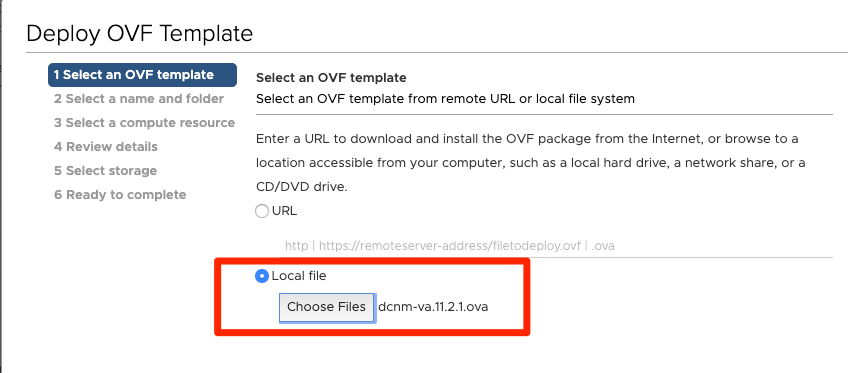
- Follow rest of prompts (VM name, which host, network settings, as shown in the image) and click on Finish.


Step 2. Once Completed, start your DCNM VM, as shown here.


Step 3. Launch web console, once in console, you should see these prompt (IP differs as this is specific to your environment and your configuration):

Step 4. Head to https://<your IP>:2443 (This is the IP you configured earlier during the OVA deployment) and click on Get Started. In this example, a Fresh installation is covered.

Step 5. Once you’ve configured the admin password, you must select the type of fabric you would like to install. Select between LAN or FAB as each type has a different purpose so be sure to understand and choose correctly. For this example, the LAN Fabric is used, it is for most VXLAN-EVPN Deployments.

Step 6. Follow the installer’s prompts with your network’s DNS, Network Time Protocol (NTP) server, DCNM hostname, etc.

Step 7. Configure the management IP and management gateway. The management network provides connectivity (SSH, SCP, HTTP, HTTPS) to the DCNM Server. This is also the IP you use to reach the GUI. The IP address should be pre-configured from you from the OVA installation done previously.
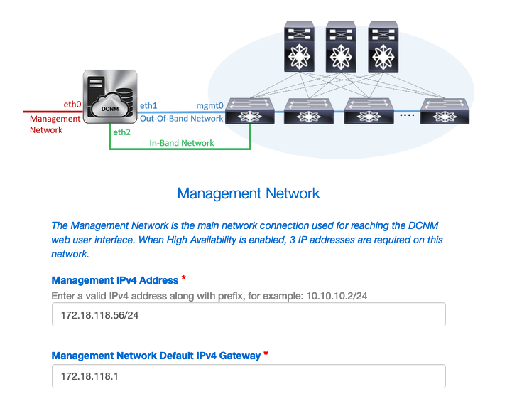

Step 8. Configure the In-Band Network. The In-Band network is used for applications such as Endpoint Locator which requires front-panel port connectivity to the 9Ks in the fabric to work as a Border Gateway Protocol (BGP) session gets established between DCNM and the 9K.

Step 9. Configure the Internal Application Services Network --
To start with DCNM 11.0 release, DCNM supports Application Framework (AFW) with DCNM LAN OVA/ISO Installation. This framework uses Docker for orchestrating applications as microservices in both clustered and unclustered environments for realizing a scale-out architecture.
Other applications that ship by default with the DCNM are Endpoint Locator, Watch Tower, Virtual Machine Manager plugin, Config Compliance etc. AFW takes care of the life cycle management of these applications including providing networking, storage, authentication, security, etc. AFW also manages deployment and life cycle of the Network Insights applications namely NIR and NIA This subnet is for Docker services when you have NIA/NIR enabled.
How to install NIA/NIR is covered under the Day 2 Operations section.

Note: This subnet should not overlap with the networks assigned to the eth0/eth1/eth2 interfaces assigned to the DCNM and the compute nodes. In addition, this subnet should not overlap with the IPs that are allocated to the switches or other devices that are managed by DCNM. The chosen subnet should remain consistent when installing the DCNM primary and secondary nodes (in case of a native HA deployment).
Step 10. Review and confirm all configuration details and start the installation.

Step 11. Once DCNM is fully installed, login to the GUI (IP address or hostname you previously configured).
Deploy the First Fabric -- RTP Fabric
Step 1. Once in the DCNM GUI, navigate to Fabric Builder. Control > Fabrics > Fabric Builder in order to create your first fabric.

Step 2. Click on Create Fabric and fill out the forms as needed for your network — Easy Fabric is the correct template for local EVPN VXLAN deployment:

Step 3. Fill out Fabric's Underlay, Overlay, vPC, Replication, Resources, etc requirements.
This section covers all the Underlay, Overlay, vPC, Replication, etc settings required via DCNM. This depends upon the network addressing scheme, requirements, etc. For this example, most fields are left as defaults. The L2VNI and L3VNI were changed such that L2VNIs start with 2 and L3VNIs start with 3 for ease to troubleshoot later. Bidirectional Forwarding Detection (BFD) is also enabled along with other features.


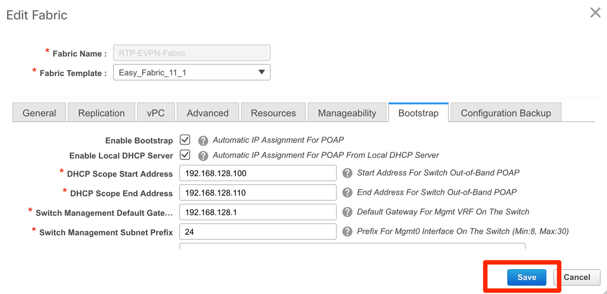
Step 4. Under the Bootstrap configuration, configure the range of DHCP Addresses you want DCNM to hand out to the switches within the Fabric during the POAP process. Configure a proper (existing) Default Gateway as well. Click on Save once you are done and now you can move on to adding switches into the fabric.
Add Switches into the Fabric
Step 1. Navigate to Control > Fabrics > Fabric Builder then select your Fabric. On the left-side panel, click on Add Switches, as shown in the image.

You can discover switches by either using a Seed IP (meaning the mgmt0 IP of each switch must be configured manually) or you can discover the switches via POAP and have DCNM configure all the mgmt0 IP addresses, VRF management, etc for you. For this example, we will be using POAP.
Step 2. Once you see the switch(es) of your interest, input the desired IP Address and Hostname you want DCNM to use, enter Admin PW, then click on Bootstrap, as shown in the image.

A successful booting log should look as shown in the image here from the switch’s console.


Step 3. Before you deploy the configuration for the entire fabric, ensure that you have previously configured DCNM with the device credentials. A popup should’ve appeared in the GUI as you login. In the event it does not, you can always access this via Administration > Credentials Management > LAN Credentials.
Note: If the device credentials are missing, DCNM fails to push configuration to the switches.


Deploy the Fabric’s Configuration
Step 1. Once you have discovered all the switches for the given fabric using the same steps, navigate to Control > Fabrics > Fabric Builder > <your selected Fabric>. You should see your switches along with all their links here. Click Save & Deploy.

Step 2. In the Config Deployment window, you see how many lines of configuration for each switch DCNM pushes. You can preview the configuration as well if desired and compare the before and after:

Ensure all switches state COMPLETED and 100% without any errors — If there are any errors, be sure to address them one at a time (see Problems Encountered During This Deployment section for examples)

Step 3. (Optional) You can login to the devices at this point and issue any show run CLIs to verify that configuration was successfully pushed by DCNM.
Example:

Deploy the Second Fabric -- SJ
Perform the same steps as before with the RTP fabric using different values for BGP AS, etc.
Step 1. Navigate to Control > Fabrics > Fabric Builder > Create Fabric > Name it!
This section covers all the Underlay, Overlay, vPC, Replication, etc settings required. This depends upon the network addressing scheme, requirements, etc.
Note: The Anycast Gateway MAC here should match the other Fabric if Multi-Site is used, later on, different Anycast Gateway MACs are not supported. This was corrected later on during the Multi-Site deployment section (not shown within article for brevity).


Step 2. Configure the Bootstrap section as done before. Navigate through Add Switches again. Once all discovered, click on Save & Deploy to deploy the configuration. This was all covered in the RTP Fabric Deployment section (omitting here for brevity).

Topology from Fabric Builder’s perspective at the end.

Ideally, all switches should appear in Green along with their links. This image shows the different status colors in DCNM mean.

Step 3. Once both fabrics are configured and deployed, ensure to save config & reload for TCAM changes to take effect. Go to Controls > Fabrics > Fabric Builder > <your Fabric>, navigate to Tabular View, as shown in the image.

Step 4. Then click the power button (this reloads all your switches simultaneously):

Create a Network (VLAN/L2VNI) and VRFs (L3VNIs)
Step 1. Navigate to Control > Fabrics > Networks, as shown in the image.

Step 2. As shown in the image, select the Scope for the change. i.e. which Fabric does this configuration need to be applied to?

Step 3. Click on the + sign, as shown in the image.

Step 4. DCNM walks you through the process to create the Switch Virtual Interface (SVI) (or pure L2 VLAN). If no VRFs are created at this stage, click the + button again and this temporarily takes you to the VRFs walk-through before moving forward with the SVI settings.


These features can be configured under the Advanced tab:
- ARP Suppression
- Ingress Replication
- Multicast Group
- DCHP
- Route Tags
- TRM
- L2 VNI Route-Target
- Enable L3 Gateway on Border
Step 5. Click on Continue to deploy the Network/VRF configuration.

Step 6. Double click on a device (or devices) in the topology view (DCNM automatically takes you here), to select them for the applicable configuration. Click on Save, as shown in the image.

Step 7. Once selected, the switches should look blue (Ready to Deploy), as shown in this image.


Note: If you want to verify the configuration for the CLI prior to deploying, you can click on Detailed View instead of Deploy and click Preview on the next screen.
The switches turn Yellow while the configuration is applied and will return to Green once it is completed.
Step 8. (Optional) You can login the CLI to verify the configuration if you so need (remember to use expand-port-profile option):

Multi-Site Configuration
For this Greenfield deployment, MSD Fabric is deployed via direct peering between Border Gateways (BGWs). An alternative is using a centralized route server, not covered in this document.
Step 1. Navigate to Control > Fabric Builder > Create Fabric, as shown in the image.

Step 2. Give your Multi-Site Fabric a name and choose MSD_Fabric_11_1 in the drop down for Fabric Template.
Step 3. Under General, ensure your L2 and L3 VNI Range matches what your individual fabrics are using. Additionally, the Anycast Gateway MAC must match on both fabrics (RTP/SJ in this example). DCNM gives you an error if the Gateway MACs are mismatched and it needs to be corrected prior to moving forward with MSD deployment.


Step 4. Click Save, then navigate to the MSD Fabric and click on Save & Deploy. Your topology should look similar to these (all switches + links Green) once successfully completed:


Deploy Host Access/Trunk Policies
For this example, vPC trunks off two different VTEP pairs are configured and test connectivity within the local RTP fabric. Relevant topology as shown in the image:

Step 1. Navigate to Control > Fabrics > Interfaces, as shown in the image.

Step 2. Click the + sign to enter the Add an Interface wizard, as shown in the image.

In this example, a vPC trunk is created downstream to the N7K which is used to ping tests in this walk-through.
Step 3. Select the appropriate vPC pair, physical interfaces, LACP on/off, BPDUGuard, etc.


Step 4. Click on Save when finished. Alternatively, you may directly Deploy, as shown in the image.


Step 5. (Optional) Review the configuration to be applied.


Step 6. (Optional) Manual configuration on 7K:

Step 7.(Optional) Creating a test SVI on N7K to ping the VTEPs in RTP (VTEPs have Anycast Gateway of 10.212.20.1 in VRF andrea_red):

Step 8. (Optional) Verify that other VTEPs within RTP see this host via EVPN/HMM:

Step 9.(Optional) Repeat the same process for seoul-bb11/12 (create vPC port-channel, create SVI 2300). Pinging from RTP-Left to RTP-Right to confirm L2 connectivity over EVPN within RTP Fabric:

Similar steps can be followed to create non-vPC port-channels, access interfaces, etc under the Add Interfaces context.
Day 2 Operations
Upgrade NX-OS Software via DCNM
Step 1. Upload an image (or set of images to DCNM’s server), and then navigate to Control > Image Management > Image Upload, as shown in the image.

Step 2. Follow the prompts for a local upload, then the file(s) should appear as shown in this image:


Step 3. Once the file(s) are uploaded, you can move on to Install & Upgrade if the switches require an upgrade. Navigate to Control > Image Management > Install & Upgrade, as shown in the image.

Step 4. Select the switches you’d like upgraded. For this example, the entire RTP Fabric is upgraded.

Step 5. Select which NX-OS version you want the switches upgraded to (as a best practice, upgrade all switches to the same NX-OS version):

Step 6. Click Next and DCNM runs the switches through pre-installation checks. This window can take quite some time, so you can alternatively select Finish Installation Later and schedule the upgrade while you’re away.

This queues the task and appears similar to as shown in the image here, once completed.

Note: The exception on the above case was one of the RTP switches did not have enough room for the NX-OS image.
Step 7. Once the compatibility is done, click on Finish Installation in the same window, as shown in the image.

Step 8. You can select the upgrades to be done concurrent (all at the same time) or sequential (one at a time). Since this is a lab environment, selected is concurrent.

The task is created and it appears IN PROGRESS, as shown in the image.


An alternate way to select the image is shown here.


Install Endpoint Locator
In order for DCNM Apps to work properly, you must have inband connectivity between the DCNM Server and a front-panel port to one of the Nexus 9000s in the Fabric. For this example, the DCNM Server is connected to Ethernet1/5 of one of the Spines in the RTP Fabric.
Step 1. This CLI is added manually to the Nexus 9000:

Step 2. Ensure that you can ping the DCNM Server and vice-versa on this point-to-point connection.

Step 3. Navigate to the DCNM GUI > Control > Endpoint Locator > Configure, as shown in the image.

Step 4. Select which Fabric you want Endpoint Locator to be enabled, as shown in the image.
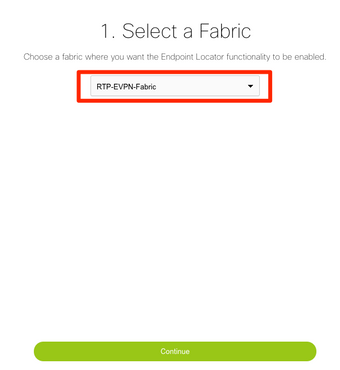
Step 5. As shown in the image, select a Spine.

Step 6. (Optional). Before moving forward to the next step, eth2’s IP was changed from the original deployment via this CLI on the DCNM Server (this step is not needed if the original IP configured during the DCNM Server fresh installation remains correct):

Step 7. Verify the In-band Interface configuration. This should match what was configured in the previous step.


Step 8. Once you review the configuration, click on Configure. This step may take a few minutes:

Once completed, the notification, as shown in the image appears.

Notice DCNM has configured a BGP neighbor on the selected Spine in the L2VPN EVPN family.

Step 9. You can now use Endpoint Locator. Navigate to Monitor > Endpoint Locator > Explore.

In this example, you can see the two hosts that were configured for the local ping tests in the RTP Fabric:

Problems Encountered During This Deployment
Bad Cabling
A pair of switches had bad cabling which caused a bundling error for the vPC peer-link port-channel500. Example:

Step 1. Navigate back to Control > Fabric Builder and review the errors:

Step 2. For the first error regarding the port-channel500 command failing — Verified via show cdp neighbors that the connection to the vPC peer was on a 10G and a 40G port (not compatible). Removed the 10G port physically and deleted the link from DCNM as well:


Failed to Configure a Feature
For the second error regarding “feature ngoam” failing to configure — The switch was upgraded to a more recent NX-OS version where “feature ngoam” is supported and click Save & Deploy again. Both issues were resolved.
Overlap the Management Subnets for Different Fabrics
While the second fabric is deployed, SJ, the same subnet was used (if physically separate, this should be OK); however, DCNM logs a conflict and POAP fails. This is resolved as the SJ Fabric is put in a different management VLAN and changing the range of the DHCP addresses.


Breakout Interfaces
Step 1. For breakout interfaces in some of the switches (refer to topology), this CLI was added manually for the T2 Spines:

Step 2. Navigate to Control > Interfaces, and delete the parent interfaces:

The actually used interfaces are Eth1/6/1-4 and Eth1/7/1-4. If you don't correct this, the Save & Deploy will fail later on. There's a way to do the breakout through DCNM itself (button next to the + sign; however, not covered in this article)
Fabric Error When Deployed to Unsupported Capability


Some of the chassis (T2s) in SJ Fabric do not support TRM so when DCNM tried to push this configuration, it was unable to move forward. TRM support here: https://www.cisco.com/c/en/us/td/docs/switches/datacenter/nexus9000/sw/92x/vxlan-92x/configuration/guide/b-cisco-nexus-9000-series-nx-os-vxlan-configuration-guide-92x/b_Cisco_Nexus_9000_Series_NX-OS_VXLAN_Configuration_Guide_9x_chapter_01001.html#concept_vw1_syb_zfb
Unchecked the TRM Enable box under both the Network and VRF Edit windows is shown in the image.
Repeat the same process under Control > Fabric Builder > VRF.

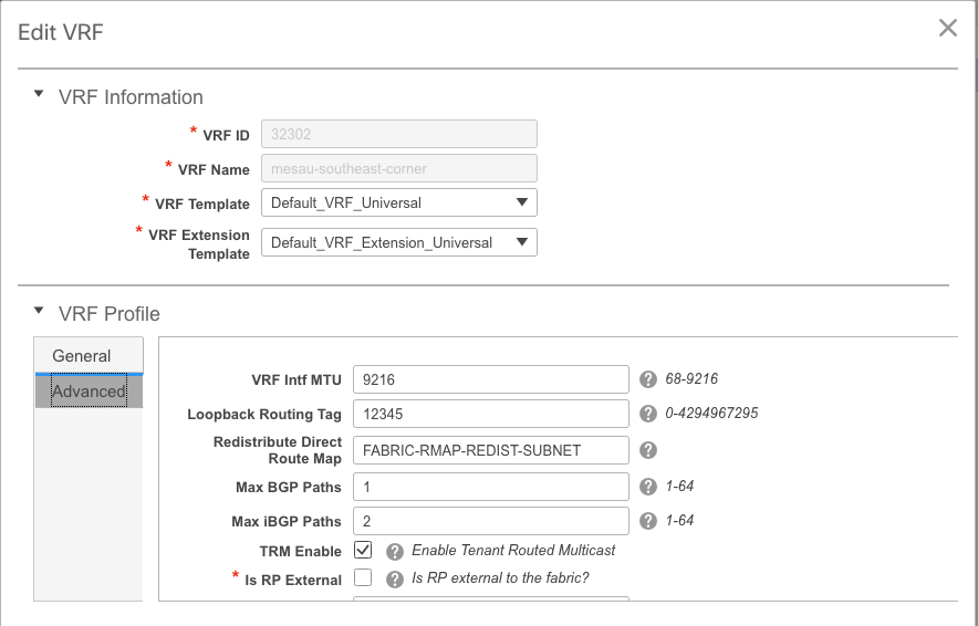

Click Continue and then Deploy respectively as done previously.
What’s new in DCNM 11.2?
-
vPC Fabric Peering
-
eBGP based Routed Fabrics
-
Enable EVPN on top
-
-
Easy Fabric Brownfield Enhancements
-
Border Spine/Border GW Spine
-
PIM Bidir
-
Tenant Routed Multicast
-
-
Day-0/Bootstrap with External DHCP server
Day 2 Operations:
-
Network Insights Resources
-
Network Insights Advisor
-
IPv6 Support for external access (eth0)
-
VMM Compute visibility with UCS-FI
-
Topology View Enhancements
-
Inline Upgrade from 11.0/11.1
Changing from traditional vPC to MCT-Less vPC using DCNM:
Benefits of MCT-Less vPC:
-
Enhanced dual-homing solution without wasting physical ports
-
Preserves traditional vPC characteristics
-
Optimized routing for singled homed endpoints with PIP
Related Information
- Cisco DCNM LAN Fabric Configuration Guide, Release 11.2(1)
https://www.cisco.com/c/en/us/td/docs/switches/datacenter/sw/11_2_1/config_guide/lanfabric/b_dcnm_fabric_lan/control.html - Chapter: Border Provisioning Use Case in VXLAN BGP EVPN Fabrics - Multi-Site
https://www.cisco.com/c/en/us/td/docs/switches/datacenter/sw/11_2_1/config_guide/lanfabric/b_dcnm_fabric_lan/border-provisioning-multisite.html - NextGen DCI with VXLAN EVPN Multi-Site Using vPC Border Gateways White Paper
https://www.cisco.com/c/en/us/products/collateral/switches/nexus-9000-series-switches/whitepaper-c11-742114.html#_Toc5275096 - Chapter: DCNM Applications
https://www.cisco.com/c/en/us/td/docs/switches/datacenter/sw/11_2_1/config_guide/lanfabric/b_dcnm_fabric_lan/applications.html
Contributed by Cisco Engineers
- Andrea TestinoCisco Engineering
Contact Cisco
- Open a Support Case

- (Requires a Cisco Service Contract)
 Feedback