Configure and Troubleshoot VXLAN vPC Fabric Peering for NXOS
Available Languages
Download Options
Bias-Free Language
The documentation set for this product strives to use bias-free language. For the purposes of this documentation set, bias-free is defined as language that does not imply discrimination based on age, disability, gender, racial identity, ethnic identity, sexual orientation, socioeconomic status, and intersectionality. Exceptions may be present in the documentation due to language that is hardcoded in the user interfaces of the product software, language used based on RFP documentation, or language that is used by a referenced third-party product. Learn more about how Cisco is using Inclusive Language.
Contents
Introduction
This document describes how to configure, verify vPC fabric peering for NXOS and BUM traffic flow.
Prerequisites
Requirements
Cisco recommends knowledge of these topics:
- vPC (virtual port-channel)
- Virtual Extensible LAN (VXLAN)
Components Used
The information in this document is based on these software and hardware versions:
- N9K-C93240YC-FX2 for Leaf switches Version: 10.3(3)
- N9K-C9336C-FX2 for Spine switch Version: 10.3(3)
The information in this document was created from the devices in a specific lab environment. All of the devices used in this document started with a cleared (default) configuration. If your network is live, ensure that you understand the potential impact of any command.
Network Diagram
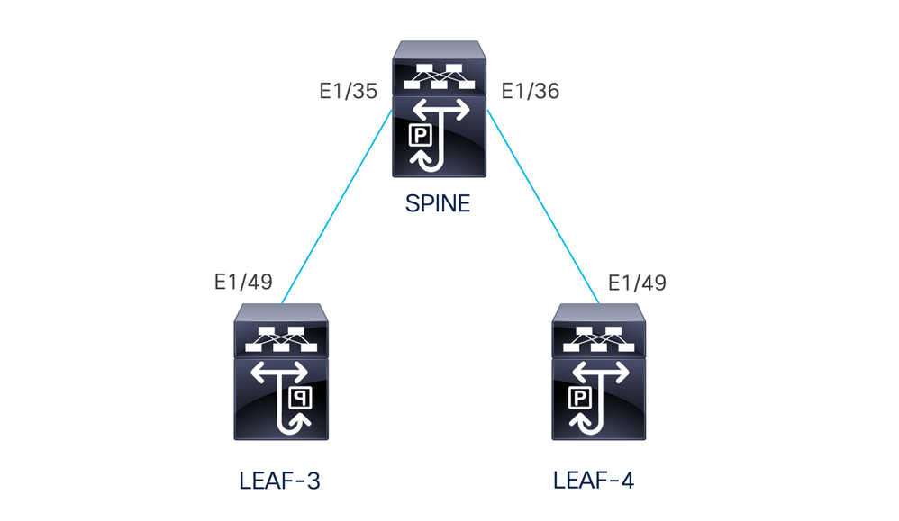
vPC Fabric Peering provides an enhanced dual-homing access solution without the overhead of wasting physical ports for vPC Peer Link. This feature preserves all the characteristics of a traditional vPC.
In this deployment we have Leaf-3 and Leaf-4 configured as vPC with fabric peering.
Configuration
TCAM Configuration
Before the configuration, there is a check on the TCAM memory:
LEAF-4(config-if)# sh hardware access-list tcam region
                                NAT ACL[nat] size = 0
                    Ingress PACL [ing-ifacl] size = 0
                                 VACL [vacl] size = 0
                     Ingress RACL [ing-racl] size = 2304
                 Ingress L2 QOS [ing-l2-qos] size = 256
       Ingress L3/VLAN QOS [ing-l3-vlan-qos] size = 512
                       Ingress SUP [ing-sup] size = 512
 Ingress L2 SPAN filter [ing-l2-span-filter] size = 256
 Ingress L3 SPAN filter [ing-l3-span-filter] size = 256
                   Ingress FSTAT [ing-fstat] size = 0
                                 span [span] size = 512
                      Egress RACL [egr-racl] size = 1792
                        Egress SUP [egr-sup] size = 256
             Ingress Redirect [ing-redirect] size = 0
                  Egress L2 QOS [egr-l2-qos] size = 0
        Egress L3/VLAN QOS [egr-l3-vlan-qos] size = 0
     Ingress Netflow/Analytics [ing-netflow] size = 512
                       Ingress NBM [ing-nbm] size = 0
                        TCP NAT ACL[tcp-nat] size = 0
          Egress sup control plane[egr-copp] size = 0
   Ingress Flow Redirect [ing-flow-redirect] size = 0 <<<<<<<<
Ingress PACL IPv4 Lite [ing-ifacl-ipv4-lite] size = 0
Ingress PACL IPv6 Lite [ing-ifacl-ipv6-lite] size = 0
                 Ingress CNTACL [ing-cntacl] size = 0
                  Egress CNTACL [egr-cntacl] size = 0
                    MCAST NAT ACL[mcast-nat] size = 0
                     Ingress DACL [ing-dacl] size = 0
     Ingress PACL Super Bridge [ing-pacl-sb] size = 0
   Ingress Storm Control [ing-storm-control] size = 0
         Ingress VACL redirect [ing-vacl-nh] size = 0
                     Egress PACL [egr-ifacl] size = 0
                Egress Netflow [egr-netflow] size = 0
vPC Fabric Peering requires the application of TCAM carving of region ing-flow-redirect. TCAM carving requires saving the configuration and reloading the switch prior to using the feature.
This space on the TCAM is double width so the minimum we can assign is 512.
TCAM Carving
In this scenario ing-racl has enough space to take 512 and assign those 512 to ing-flow-redirect.
LEAF-4(config-if)# hardware access-list tcam region ing-racl 1792
Please save config and reload the system for the configuration to take effect

LEAF-4(config)# hardware access-list tcam region ing-flow-redirect 512
Please save config and reload the system for the configuration to take effect

Note: When configuring vPC fabric peering through DCNM the TCAM carving is going to be done but it requires a reload to take effect
Once the change has been done, it is going to get reflected on the command:
513E-B-11-N9K-C93240YC-FX2-4# sh hardware access-list tcam region
                                         NAT ACL[nat] size = 0
                             Ingress PACL [ing-ifacl] size = 0
                                          VACL [vacl] size = 0
                              Ingress RACL [ing-racl] size = 2304
                          Ingress L2 QOS [ing-l2-qos] size = 256
                Ingress L3/VLAN QOS [ing-l3-vlan-qos] size = 512
                                Ingress SUP [ing-sup] size = 512
          Ingress L2 SPAN filter [ing-l2-span-filter] size = 256
          Ingress L3 SPAN filter [ing-l3-span-filter] size = 256
                            Ingress FSTAT [ing-fstat] size = 0
                                          span [span] size = 512
                               Egress RACL [egr-racl] size = 1792
                                 Egress SUP [egr-sup] size = 256
                      Ingress Redirect [ing-redirect] size = 0
                           Egress L2 QOS [egr-l2-qos] size = 0
                 Egress L3/VLAN QOS [egr-l3-vlan-qos] size = 0
              Ingress Netflow/Analytics [ing-netflow] size = 512 <<<<<
                                Ingress NBM [ing-nbm] size = 0
                                 TCP NAT ACL[tcp-nat] size = 0
                   Egress sup control plane[egr-copp] size = 0
            Ingress Flow Redirect [ing-flow-redirect] size = 0
         Ingress PACL IPv4 Lite [ing-ifacl-ipv4-lite] size = 0
         Ingress PACL IPv6 Lite [ing-ifacl-ipv6-lite] size = 0
                          Ingress CNTACL [ing-cntacl] size = 0
                           Egress CNTACL [egr-cntacl] size = 0
                             MCAST NAT ACL[mcast-nat] size = 0
                              Ingress DACL [ing-dacl] size = 0
              Ingress PACL Super Bridge [ing-pacl-sb] size = 0
            Ingress Storm Control [ing-storm-control] size = 0
                  Ingress VACL redirect [ing-vacl-nh] size = 0
                              Egress PACL [egr-ifacl] size = 0

Caution: Make sure that the device is reloaded after the changes on the TCAM, else the VPC is not going to come up due to changes not applied on the TCAM.
Configuration for vPC
VPC Domain
On the LEAF-3 and LEAF-4 in the VPC domain the configuration is to specify the IP addresses for the keep-alive and the Virtual peer link
vpc domain 1
  peer-keepalive destination 192.168.1.1 source 192.168.1.2 vrf management
  virtual peer-link destination 10.10.10.2 source 10.10.10.1 dscp 56

interface port-channel1
  vpc peer-link
Keep-alive
Any direct Layer 3 link between vPC peers must be used only for peer-keep alive. It must be in a separate VRF dedicated for the keep-alive only. In this scenario we are using the interface management of the switch.
LEAF-3
interface mgmt0
  vrf member management
  ip address 192.168.1.1/24

LEAF-4
interface mgmt0
  vrf member management
  ip address 192.168.1.2/24
Layer 3 Interface for the Virtual Peer-link
The Layer 3 interface used for the virtual peer-link must not be the same we use for the keep-alive, you can use the same loopback used for the underlay or it can be a dedicated loopback on the Nexus
Here the loopback0 is for the underlay and the loopback2 is a dedicated loopback for the virtual peer-link, while loopback1 is the interface associated to our interface NVE.
LEAF-3
interface loopback0
  ip address 10.1.1.1/32
  ip router ospf 1 area 0.0.0.0
  ip pim sparse-mode

interface loopback1
  ip address 172.16.1.2/32
  ip address 172.16.1.1/32 secondary
  ip router ospf 1 area 0.0.0.0
  ip pim sparse-mode

interface loopback2
  ip address 10.10.10.2/32
  ip router ospf 1 area 0.0.0.0


LEAF-4
interface loopback0
  ip address 10.1.1.2/32
  ip router ospf 1 area 0.0.0.0
  ip pim sparse-mode

interface loopback1
  ip address 172.16.1.3/32
  ip address 172.16.1.1/32 secondary
  ip router ospf 1 area 0.0.0.0
  ip pim sparse-mode

interface loopback2
  ip address 10.10.10.1/32
  ip router ospf 1 area 0.0.0.0
VPC Peer-link
The peer-link need to have a port-channel assigned even if we are not going to assign a physical interface to the port-channel.
LEAF-3(config-if)# sh run interface port-channel 1 membership

interface port-channel1
  switchport
  switchport mode trunk
  spanning-tree port type network
  vpc peer-link
Up-links
The last part of the configuration is to configure the links on both leafs towards the SPINE with the command port-type fabric.
interface Ethernet1/49
  port-type fabric <<<<<<<<
  medium p2p
  ip unnumbered loopback0
  ip router ospf 1 area 0.0.0.0
  ip pim sparse-mode
  no shutdown

Note: If you do not configure the port-type fabric you can not see the keep-alive being generated by the Nexus
SPINES Configuration
On the spines it is recommended to set QoS to match the DSCP value configured on the VPC domain since the vPC Fabric Peering peer-link is established over the transport network.
Control plane information CFS messages used to synchronize port state information, VLAN information, VLAN-to-VNI mapping, host MAC addresses, and IGMP snooping groups are transmitted over the fabric. CFS messages are marked with the appropriate DSCP value, which must be protected in the transport network.
class-map type qos match-all CFS
  match dscp 56

policy-map type qos CFS
  class CFS
    Set qos-group 7 <<< Depending on the platform it can be 4

interface Ethernet 1/35-36
  service-policy type qos input CFS
Broadcast, Unknown Unicast, and Multicast Traffic with Ingress Replication Encapsulation
When the nexus receives a packet that needs to be broadcasted it generates 2 copies of the packet.
1. To all remote VTEPS in the flood list for the VNI including local access ports
2. To the remote VPC peer
For the first copy, the Nexus encapsulated the traffic using the source IP of the secondary IP address and the Destination IP of the remote VTEP and also to local access ports.
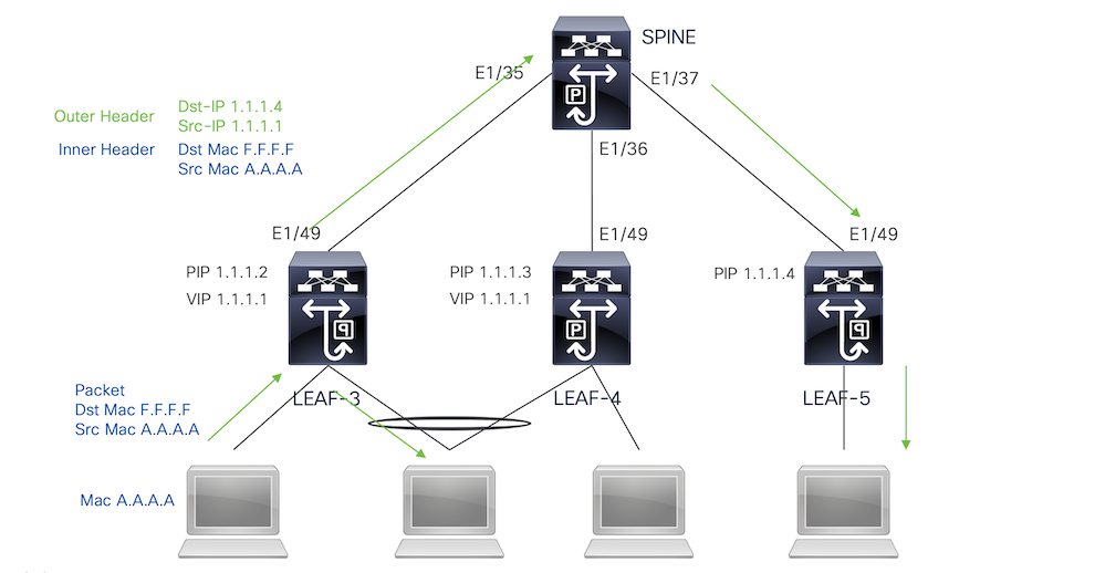
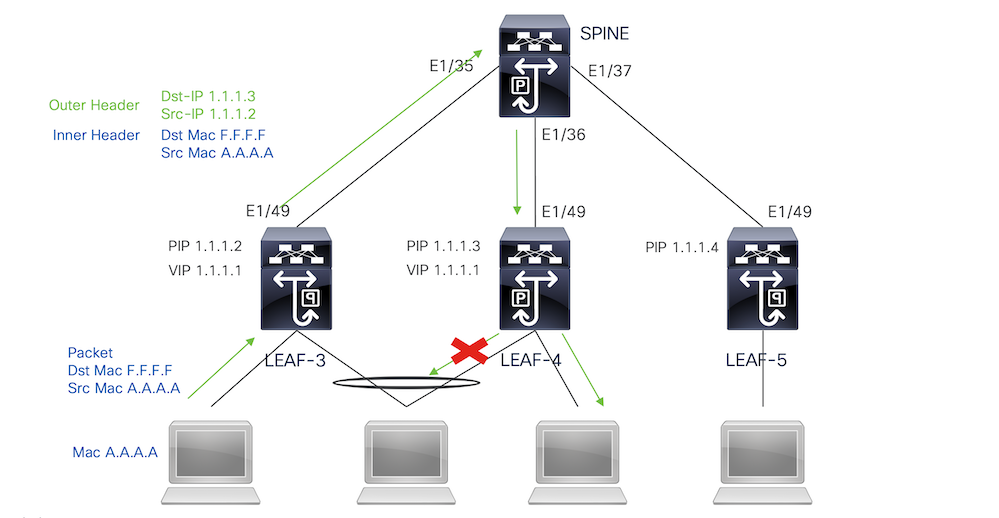
For the Second copy it is going to be sent to the remote VPC peer the source IP is going to be the primary of the loopback and the destination IP is the PIP of the remote VPC peer.
Once received the packet from the spine the remote VTEP is going to only forward the packet to the orphan ports.
Broadcast, Unknown Unicast, and Multicast Traffic with Ingress Replication Decapsulation
Since the destination IP for BUM traffic received from another VTEP is the VIP the traffic hashes to one of the VPC devices, it decapsulates the packet and send it to the access ports.
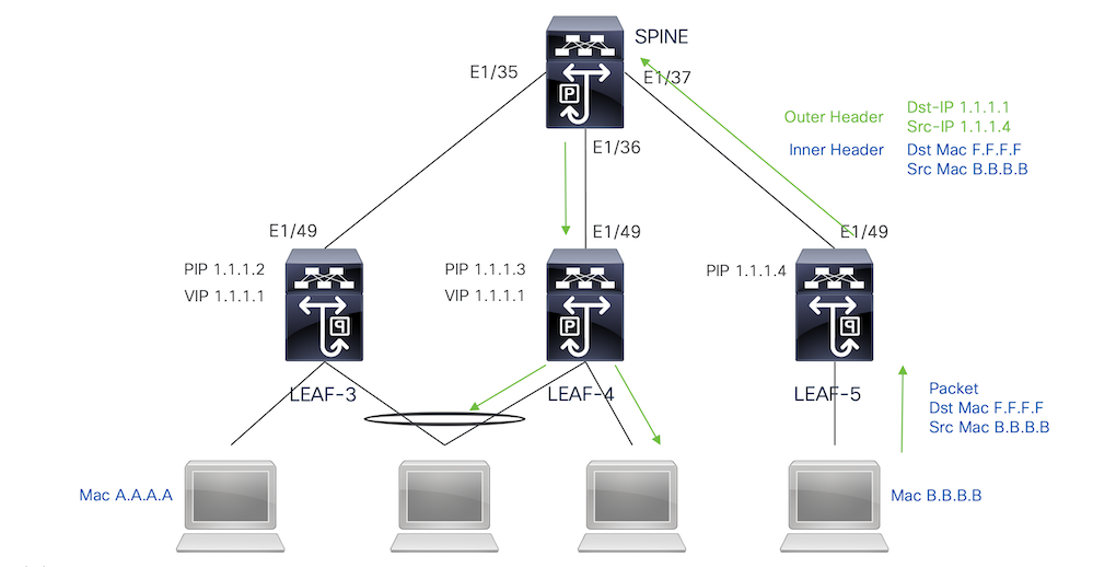
In order to make the traffic reach to the orphan ports connected on the remote VPC peer, the nexus generates a copy of the packet and is going to send it only to the remote VPC using the primary IP address as source/destination IP.
Once received on the remote vpc peer, the nexus decapsulates the traffic and forward it only to orphan ports.
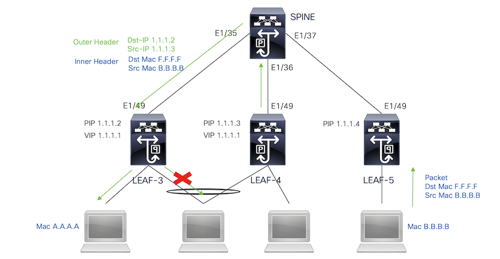
Broadcast, Unknown Unicast, and Multicast Traffic with Multicast Encapsulation
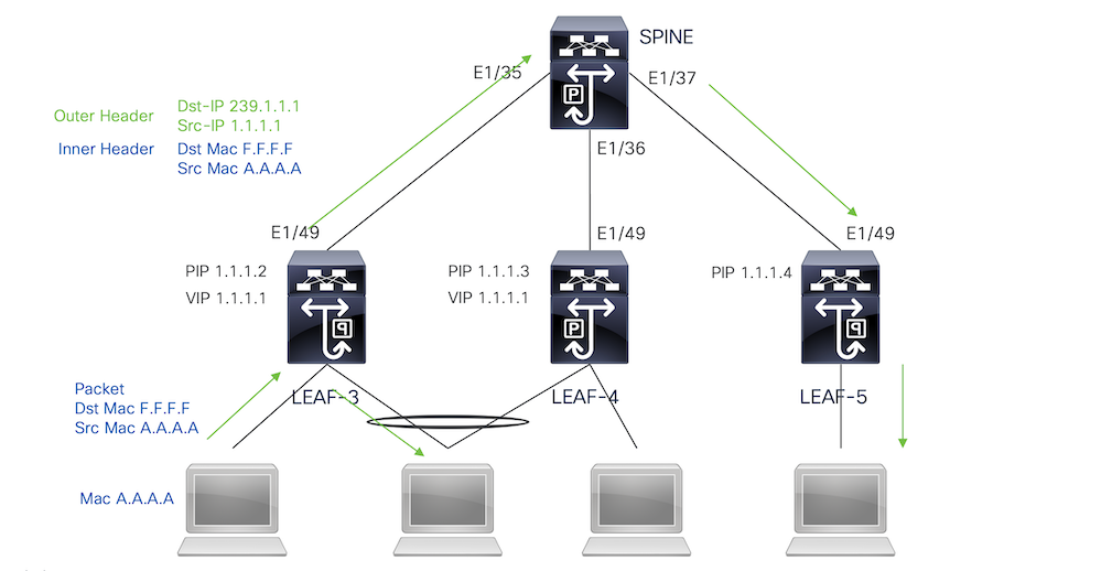
When the nexus receives a packet that needs to be broadcasted it generates 2 copies of the packet.
1. The packet is going to be sent to all the OIFs in the multicast S,G entry including local access ports
2. To the remote VPC peer
For the first copy, the Nexus encapsulated the traffic using the source IP of the secondary IP address and the Destination IP of the multicast group configured.
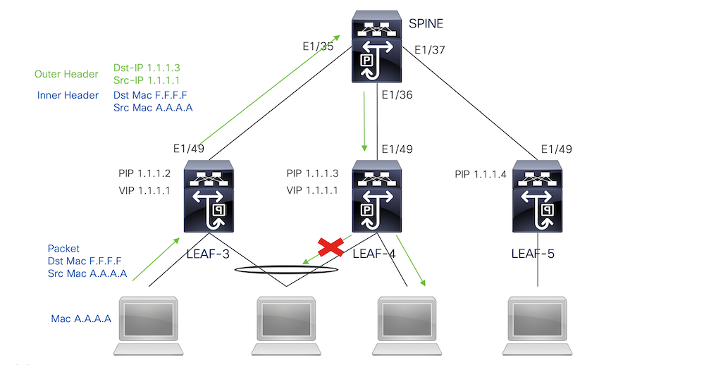
For the Second copy it is going to be sent to the remote VPC peer the source IP is going to be the secondary of the loopback and the destination IP is the PIP of the remote VPC peer.
Once received the packet from the spine the remote VTEP only forwards the packet to the orphan ports.
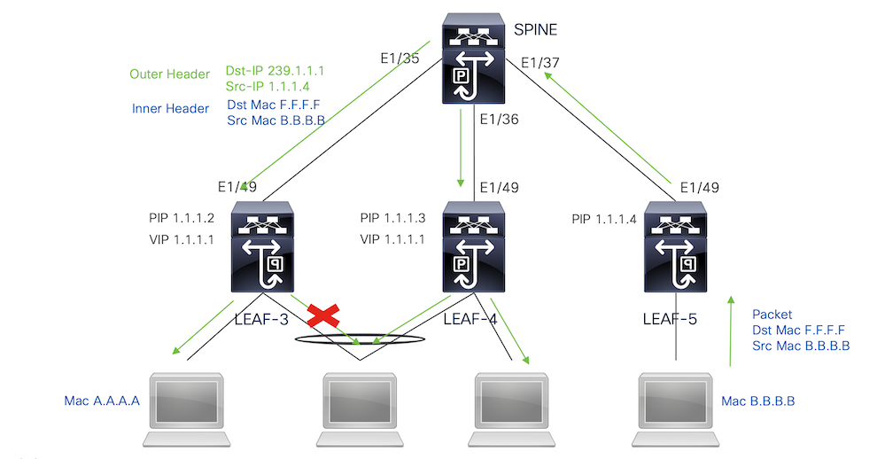
Broadcast, Unknown Unicast, and Multicast Traffic with Multicast Decapsulation
For the decapsulation process, the packet is going to arrive to both VPC peers. Only one VPC device is going to forward the traffic through the VPC port-channels. this is going to be decided by the Forwarder displayed in the command.
module-1# show forwarding internal vpc-df-hash

VPC DF: FORWARDER
Verify
To ensure the VPC is up run the next commands:
Verify reachability for the IP addresses used for the virtual peer-link.
LEAF-3# sh ip route 10.10.10.1
IP Route Table for VRF "default"
'*' denotes best ucast next-hop
'**' denotes best mcast next-hop
'[x/y]' denotes [preference/metric]
'%<string>' in via output denotes VRF <string>

10.10.10.1/32, ubest/mbest: 1/0
    *via 192.168.120.1, Eth1/49, [110/3], 01:15:01, ospf-1, intra

LEAF-3# ping 10.10.10.1
PING 10.10.10.1 (10.10.10.1): 56 data bytes
64 bytes from 10.10.10.1: icmp_seq=0 ttl=253 time=0.898 ms
64 bytes from 10.10.10.1: icmp_seq=1 ttl=253 time=0.505 ms
64 bytes from 10.10.10.1: icmp_seq=2 ttl=253 time=0.433 ms
64 bytes from 10.10.10.1: icmp_seq=3 ttl=253 time=0.465 ms
64 bytes from 10.10.10.1: icmp_seq=4 ttl=253 time=0.558 ms
LEAF-3(config-if)# show vpc brief
Legend:
                (*) - local vPC is down, forwarding via vPC peer-link

vPC domain id                          : 1
Peer status                            : peer adjacency formed ok <<<<
vPC keep-alive status                  : peer is alive <<<<
Configuration consistency status       : success
Per-vlan consistency status            : success
Type-2 consistency status              : success
vPC role                               : secondary
Number of vPCs configured              : 0
Peer Gateway                           : Disabled
Dual-active excluded VLANs             : -
Graceful Consistency Check             : Enabled
Auto-recovery status                   : Disabled
Delay-restore status                   : Timer is off.(timeout = 30s)
Delay-restore SVI status               : Timer is off.(timeout = 10s)
Delay-restore Orphan-port status       : Timer is off.(timeout = 0s)
Operational Layer3 Peer-router         : Disabled
Virtual-peerlink mode                  : Enabled <<<<<<<

vPC Peer-link status
---------------------------------------------------------------------
id  Port  Status  Active vlans
--  ----  ------  -------------------------------------------------
1   Po1   up      1,10,50,600-604,608,610-611,614-618,638-639,
                  662-663,701-704
To check the roles for the VPC run the command:
LEAF-3(config-if)# sh vpc role

vPC Role status
----------------------------------------------------
vPC role                             : secondary <<<<
Dual Active Detection Status         : 0
vPC system-mac                       : 00:23:04:ee:be:01
vPC system-priority                  : 32667
vPC local system-mac                 : d0:e0:42:e2:09:6f
vPC local role-priority              : 32667
vPC local config role-priority       : 32667
vPC peer system-mac                  : 2c:4f:52:3f:46:df
vPC peer role-priority               : 32667
vPC peer config role-priority        : 32667
All the vlans allowed in the peer-link port-channel must be mapped to a VNI, in case they are not they are going to be displayed as inconsistent
LEAF-3(config-if)# show vpc virtual-peerlink vlan consistency
Following vlans are inconsistent
1 608 610 611 614 615 616 617 618 638 639 701 702 703 704
To confirm the configuration on the up-links is correctly programmed run the command:
LEAF-3(config-if)# show vpc fabric-ports
Number of Fabric port : 1
Number of Fabric port active : 1

Fabric   Ports      State
-------------------------------------
Ethernet 1/49       UP

Note: The NVE nor the loopback interface associated to it are going to show up unless the VPC is up.
Related Information
Revision History
| Revision | Publish Date | Comments |
|---|---|---|
1.0 |
05-Oct-2023 |
Initial Release |
Contributed by Cisco Engineers
- Jorge Garcia FernandezCisco Escalation Engineer
Contact Cisco
- Open a Support Case

- (Requires a Cisco Service Contract)
 Feedback