IOS Router as Easy VPN Server Using Configuration Professional Configuration Example
Available Languages
Contents
Introduction
This document describes how to configure a Cisco IOS® Router as an Easy VPN (EzVPN) Server using Cisco Configuration Professional (Cisco CP) and the CLI. The Easy VPN Server feature allows a remote end user to communicate using IP Security (IPsec) with any Cisco IOS Virtual Private Network (VPN) gateway. Centrally managed IPsec policies are "pushed" to the client device by the server, minimizing configuration by the end user.
For more information on Easy VPN Server refer to the Easy VPN Server section of Secure Connectivity Configuration Guide Library, Cisco IOS Release 12.4T.
Prerequisites
Components Used
The information in this document is based on these software and hardware versions:
-
Cisco 1841 Router with Cisco IOS Software Release 12.4(15T)
-
Cisco CP Version 2.1
The information in this document was created from the devices in a specific lab environment. All of the devices used in this document started with a cleared (default) configuration. If your network is live, make sure that you understand the potential impact of any command.
Install Cisco CP
Perform these steps in order to install Cisco CP:
-
Download Cisco CP V2.1 from the Cisco Software Center (registered customers only) and install it on your local PC.
The latest version of Cisco CP can be found at the Cisco CP website.
-
Launch Cisco CP from your local PC through Start > Programs > Cisco Configuration Professional (CCP) and choose the Community which has the router you want to configure.
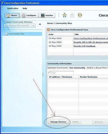
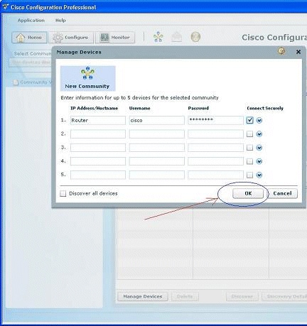
-
In order to discover the device you want to configure, highlight the router and click Discover.
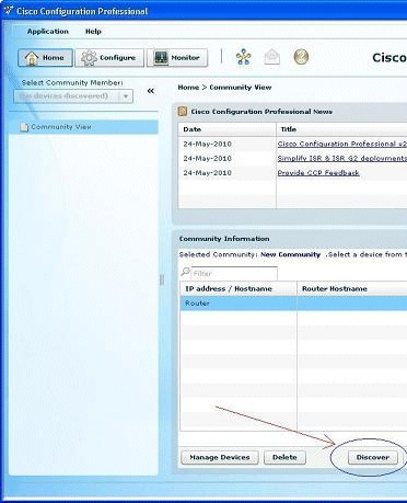
Note: For information on the Cisco router models and IOS releases that are compatible to Cisco CP v2.1, refer to the Compatible Cisco IOS releases section.
Note: For information on the PC requirements that runs Cisco CP v2.1, refer to the System Requirements section.
Router Configuration to Run Cisco CP
Perform these configuration steps in order to run Cisco CP on a Cisco router:
-
Connect to your router using Telnet, SSH, or through the console.
Enter global configuration mode using this command:
Router(config)#enable
Router(config)#
-
If HTTP and HTTPS are enabled and configured to use nonstandard port numbers, you can skip this step and simply use the port number already configured.
Enable the router HTTP or HTTPS server using these Cisco IOS Software commands:
Router(config)# ip http server
Router(config)# ip http secure-server
Router(config)# ip http authentication local
-
Create a user with privilege level 15:
Router(config)# username <username> privilege 15 password 0 <password>
Note: Replace <username> and <password> with the username and password that you want to configure.
-
Configure SSH and Telnet for local log in and privilege level 15.
Router(config)# line vty 0 4
Router(config-line)# privilege level 15
Router(config-line)# login local
Router(config-line)# transport input telnet
Router(config-line)# transport input telnet ssh
Router(config-line)# exit
-
(Optional) Enable local logging to support the log monitoring function:
Router(config)# logging buffered 51200 warning
Requirements
This document assumes that the Cisco router is fully operational and configured to allow Cisco CP to make configuration changes.
For complete information on how to start using Cisco CP, refer to Getting Started with Cisco Configuration Professional.
Conventions
Refer to the Cisco Technical Tips Conventions for more information on document conventions.
Configure
In this section, you are presented with the information to configure the basic settings for a router in a network.
Note: Use the Command Lookup Tool (registered customers only) to obtain more information on the commands used in this section.
Network Diagram
This document uses this network setup:

Note: The IP addressing schemes used in this configuration are not legally routable on the Internet. They are RFC 1918 ![]() addresses which have been used in a lab environment.
addresses which have been used in a lab environment.
Cisco CP - Easy VPN Server Configuration
Perform these steps in order to configure the Cisco IOS router as an Easy VPN Server:
-
Choose Configure > Security > VPN > Easy VPN Server > Create Easy VPN Server and click Launch Easy VPN Server Wizard in order to configure the Cisco IOS router as an Easy VPN Server:
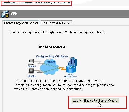
-
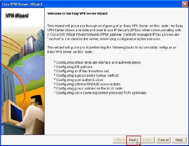
Click Next in order to proceed with the Easy VPN Server configuration.
-
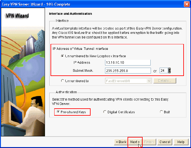
In the resulting window, a Virtual Interface will be configured as a part of the Easy VPN Server configuration. Provide the IP Address of the Virtual Tunnel Interface and also choose the Authentication method used for authenticating the VPN clients. Here, Pre-shared Keys is the authentication method used. Click Next:
-
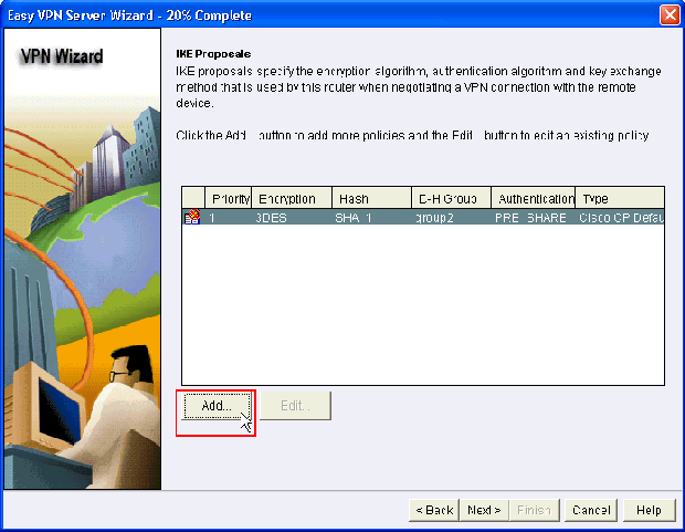
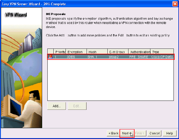
Specify the Encryption algorithm, authentication algorithm and key exchange method to be used by this router when negotiating with the remote device. A default IKE policy is present on the router which can be used if required. If you want to add a new IKE policy, click Add.
-
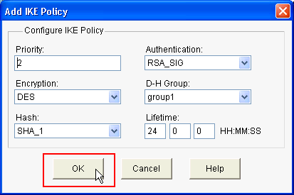
Provide Encryption Algorithm, Authentication Algorithm, and the Key Exchange method as shown here, then click OK:
-
The Default IKE policy is used in this example. As a result, choose the default IKE policy and click Next.
-
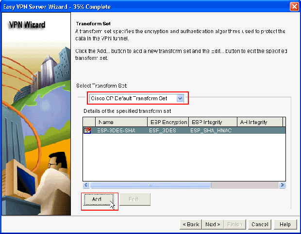
In the new window, the Transform Set details should be provided. The Transform Set specifies the Encryption and Authentication algorithms used to protect Data in VPN Tunnel. Click Add to provide these details. You can add any number of Transform Sets as needed when you click Add and provide the details.
Note: CP Default Transform Set is present by default on the router when configured using Cisco CP.
-
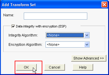
Provide the Transform Set details (Encryption and Authentication Algorithm) and click OK.
-
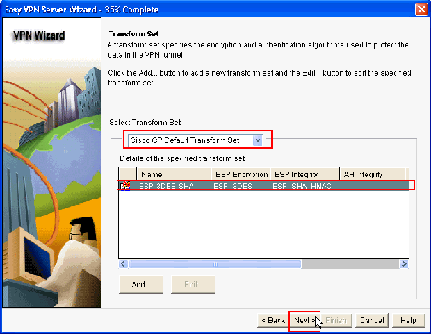
The Default Transform Set named CP Default Transform Set is used in this example. As a result, choose the default Transform Set and click Next.
-
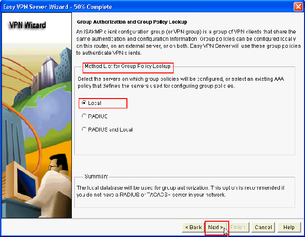
In the new window, choose the server on which the group policies will be configured which can be either Local or RADIUS or both Local and RADIUS. In this example, we use Local server to configure group policies. Choose Local and click Next.
-
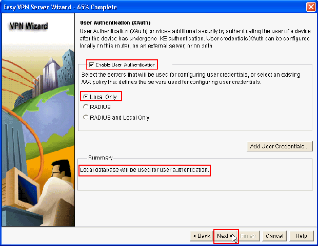
Choose the server to be used for User Authentication in this new window which can be either Local Only or RADIUS or both Local Only and RADIUS. In this example we use Local server to configure User credentials for authentication. Make sure the check box next to Enable User Authentication is checked. Choose Local Only and click Next.
-
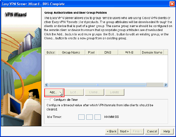
Click Add to create a new group policy and to add the remote users in this group.
-
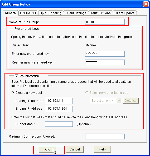
In the Add Group Policy window, provide the group name in the space provide for Name of This Group (cisco in this example) along with Pre-shared key, and the IP Pool (the Starting IP address and Ending IP address) information as shown and click OK.
Note: You can create a new IP pool or use an existing IP pool if present.
-
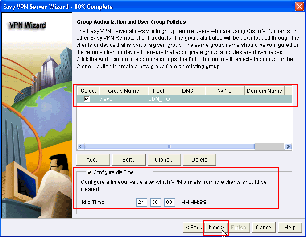
Now choose the new Group Policy created with the name cisco and then click the check box next to Configure Idle Timer as required in order to configure the Idle Timer. Click Next.
-
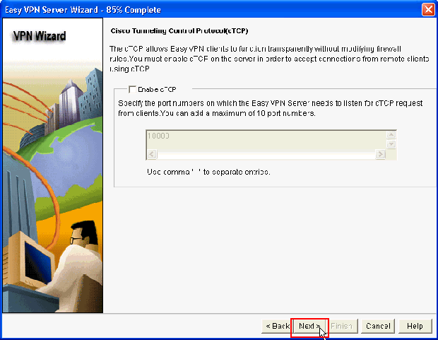
Enable Cisco Tunneling Control Protocol (cTCP) if required. Otherwise, click Next.
-
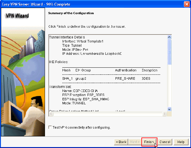
Review the Summary of the Configuration. Click Finish.
-
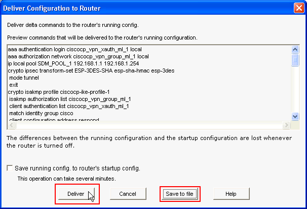
In the Deliver Configuration to Router window, click Deliver to deliver the configuration to the router. You can click on Save to file to save the configuration as a file on the PC.
-
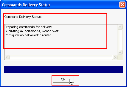
The Command Delivery Status window shows the delivery status of the commands to the router. It appears as Configuration delivered to router. Click OK.
-
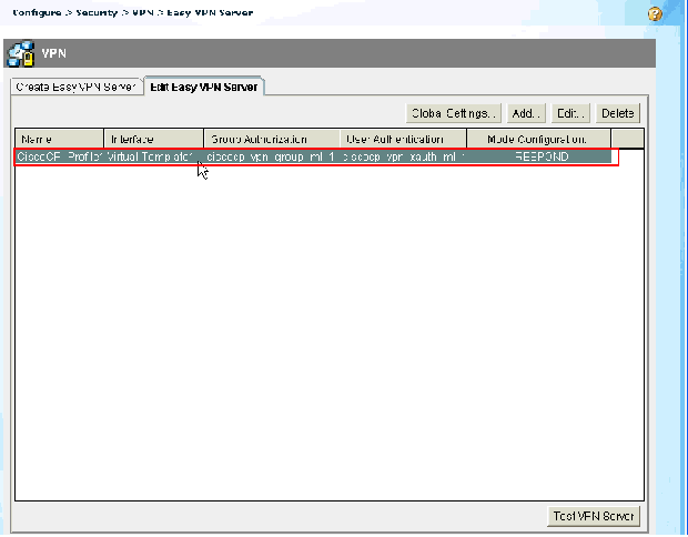
You can see the newly created Easy VPN Server. You can edit the existing server by choosing Edit Easy VPN Server. This completes the Easy VPN Server configuration on the Cisco IOS Router.
CLI Configuration
| Router Configuration |
|---|
Router#show run Building configuration... Current configuration : 2069 bytes ! version 12.4 service timestamps debug datetime msec service timestamps log datetime msec no service password-encryption hostname Router boot-start-marker boot-end-marker no logging buffered enable password cisco !---AAA enabled using aaa newmodel command. Also AAA Authentication and Authorization are enabled---! aaa new-model ! ! aaa authentication login ciscocp_vpn_xauth_ml_1 local aaa authorization network ciscocp_vpn_group_ml_1 local ! ! aaa session-id common ip cef ! ! ! ! ip domain name cisco.com ! multilink bundle-name authenticated ! ! !--- Configuration for IKE policies. !--- Enables the IKE policy configuration (config-isakmp) !--- command mode, where you can specify the parameters that !--- are used during an IKE negotiation. Encryption and Policy details are hidden as the default values are chosen. crypto isakmp policy 1 encr 3des authentication pre-share group 2 crypto isakmp keepalive 10 ! crypto isakmp client configuration group cisco key cisco123 pool SDM_POOL_1 crypto isakmp profile ciscocp-ike-profile-1 match identity group cisco client authentication list ciscocp_vpn_xauth_ml_1 isakmp authorization list ciscocp_vpn_group_ml_1 client configuration address respond virtual-template 1 ! ! !--- Configuration for IPsec policies. !--- Enables the crypto transform configuration mode, !--- where you can specify the transform sets that are used !--- during an IPsec negotiation. crypto ipsec transform-set ESP-3DES-SHA esp-3des esp-sha-hmac ! crypto ipsec profile CiscoCP_Profile1 set security-association idle-time 86400 set transform-set ESP-3DES-SHA set isakmp-profile ciscocp-ike-profile-1 ! ! ! !--- RSA certificate generated after you enable the !--- ip http secure-server command. crypto pki trustpoint TP-self-signed-1742995674 enrollment selfsigned subject-name cn=IOS-Self-Signed-Certificate-1742995674 revocation-check none rsakeypair TP-self-signed-1742995674 !--- Create a user account named cisco123 with all privileges. username cisco123 privilege 15 password 0 cisco123 archive log config hidekeys ! ! !--- Interface configurations are done as shown below---! interface Loopback0 ip address 10.10.10.10 255.255.255.0 ! interface FastEthernet0/0 ip address 10.77.241.111 255.255.255.192 duplex auto speed auto ! interface Virtual-Template1 type tunnel ip unnumbered Loopback0 tunnel mode ipsec ipv4 tunnel protection ipsec profile CiscoCP_Profile1 ! !--- VPN pool named SDM_POOL_1 has been defined in the below command---! ip local pool SDM_POOL_1 192.168.1.1 192.168.1.254 !--- This is where the commands to enable HTTP and HTTPS are configured. ip http server ip http authentication local ip http secure-server ! ! ! ! control-plane ! line con 0 line aux 0 !--- Telnet enabled with password as cisco. line vty 0 4 password cisco transport input all scheduler allocate 20000 1000 ! ! ! ! end |
Verify
Easy VPN Server - show Commands
Use this section to confirm that your configuration works properly.
-
show crypto isakmp sa—Shows all current IKE SAs at a peer.
Router#show crypto isakmp sa

IPv4 Crypto ISAKMP SA
dst             src             state          conn-id slot status
10.77.241.111   172.16.1.1     QM_IDLE           1003    0 ACTIVE
-
show crypto ipsec sa—Shows all current IPsec SAs at a peer.
Router#show crypto ipsec sa
		interface: Virtual-Access2
    Crypto map tag: Virtual-Access2-head-0, local addr 10.77.241.111

   protected vrf: (none)
   local  ident (addr/mask/prot/port): (0.0.0.0/0.0.0.0/0/0)
   remote ident (addr/mask/prot/port): (192.168.1.3/255.255.255.255/0/0)
   current_peer 172.16.1.1 port 1086
     PERMIT, flags={origin_is_acl,}
    #pkts encaps: 28, #pkts encrypt: 28, #pkts digest: 28
    #pkts decaps: 36, #pkts decrypt: 36, #pkts verify: 36
    #pkts compressed: 0, #pkts decompressed: 0
    #pkts not compressed: 0, #pkts compr. failed: 0
    #pkts not decompressed: 0, #pkts decompress failed: 0
    #send errors 0, #recv errors 2

     local crypto endpt.: 10.77.241.111, remote crypto endpt.: 172.16.1.1
     path mtu 1500, ip mtu 1500, ip mtu idb FastEthernet0/0
     current outbound spi: 0x186C05EF(409732591)

     inbound esp sas:
      spi: 0x42FC8173(1123844467)
        transform: esp-3des esp-sha-hmac
Troubleshoot
The Output Interpreter Tool (registered customers only) (OIT) supports certain show commands. Use the OIT to view an analysis of show command output.
Note: Refer to Important Information on Debug Commands before you issue debug commands.
Related Information
Revision History
| Revision | Publish Date | Comments |
|---|---|---|
1.0 |
17-Jun-2010 |
Initial Release |
Contact Cisco
- Open a Support Case

- (Requires a Cisco Service Contract)


 Feedback