ASAv in GoTo (L3) Mode with the Use of AVS- ACI 1.2(x) Release
Available Languages
Bias-Free Language
The documentation set for this product strives to use bias-free language. For the purposes of this documentation set, bias-free is defined as language that does not imply discrimination based on age, disability, gender, racial identity, ethnic identity, sexual orientation, socioeconomic status, and intersectionality. Exceptions may be present in the documentation due to language that is hardcoded in the user interfaces of the product software, language used based on RFP documentation, or language that is used by a referenced third-party product. Learn more about how Cisco is using Inclusive Language.
Contents
Introduction
This document decribes how to deploy an Application Virtual Switch (AVS) switch with an Adaptive Security Virtual Appliance (ASAv) single firewall in Routed/GOTO mode as a L4-L7 Service Graph between two End Point Groups (EPGs) to establish client-to-server communication using ACI 1.2(x) Release.
Prerequisites
Requirements
Cisco recommends that you have knowledge of these topics:
- Access Policies configured and interfaces up and in service
- EPG, Bridge Domain (BD) and Virtual Routing and Forwarding (VRF) already configured
Components Used
The information in this document is based on these software and hardware versions:
Hardware & Software:
- UCS C220 - 2.0(6d)
- ESXi/vCenter - 5.5
- ASAv - asa-device-pkg-1.2.4.8
- AVS - 5.2.1.SV3.1.10
- APIC - 1.2(1i)
- Leaf/Spines - 11.2(1i)
- Device packages *.zip already downloaded
Features:
- AVS
- ASAv
- EPGs, BD, VRF
- Access Control List (ACL)
- L4-L7 Service Graph
- vCenter
The information in this document was created from the devices in a specific lab environment. All of the devices used in this document started with a cleared (default) configuration. If your network is live, make sure that you understand the potential impact of any command.
Configure
Network Diagram
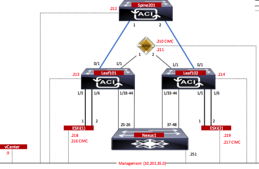
As shown in the image,
Configurations
AVS Initial Setup creates a VMware vCenter Domain (VMM integration)2
Note:
- You can create multiple datacenters and Distributed Virtual Switch (DVS) entries under a single domain. However, you can have only one Cisco AVS assigned to each datacenter.
- Service graph deployment with Cisco AVS is supported from Cisco ACI Release 1.2(1i) with Cisco AVS Release 5.2(1)SV3(1.10). The entire service graph configuration is performed on the Cisco Application Policy Infrastructure Controller (Cisco APIC).
- Service Virtual Machine (VM) deployment with Cisco AVS is supported only on Virtual Machine Manager (VMM) domains with Virtual Local Area Networks (VLAN) encapsulation mode. However, the compute VMs (the provider and consumer VMs) can be part of VMM domains with Virtual Extensible LAN (VXLAN) or VLAN encapsulation.
- Also note that if local switching is used, Multicast address and pool are not required. If no local switching is selected, then Multicast pool has to be configured and the AVS Fabric-wide multicast address should not part of the Multicast pool. All traffic originated from the AVS will be either VLAN or VXLAN encapsulated.
Navigate to VM Networking > VMWare > Create vCenter Domain, as shown in the image:

If you’re using Port-channel or VPC (Virtual Port-channel) it is recommended to set the vSwitch policies to use Mac Pinning.
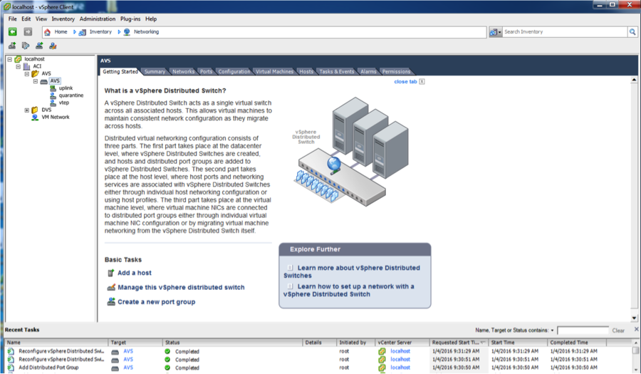
After this, APIC should push AVS switch configuration to vCenter, as shown in the image:
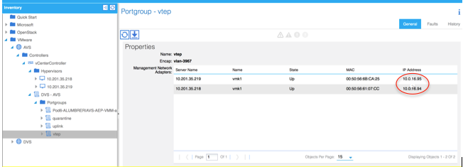
On APIC you can notice that a VXLAN Tunnel Endpoint (VTEP) address is assigned to the VTEP port-group for AVS. This address is assigned no matter what Connectivity mode is used (VLAN or VXLAN)
Install the Cisco AVS software in vCenter
- Download vSphere Installation Bundle (VIB) from CCO using this link
Note:In this case we are using ESX 5.5, Table 1, shows the Compatibility matrix for ESXi 6.0, 5.5, 5.1, and 5.0
Table 1 - Host Software Version Compatibility for ESXi 6.0, 5.5, 5.1, and 5.0

Within the ZIP file there are 3 VIB files, one for each of the ESXi host versions, select the one appropiate for ESX 5.5, as shown in the image:

- Copy the VIB file to ESX Datastore - this can be done via CLI or directly from vCenter
Note: If a VIB file exists on the host, remove it by using the esxcli software vib remove command.
esxcli software vib remove -n cross_cisco-vem-v197-5.2.1.3.1.5.0-3.2.1.vib
or by browsing the Datastore directly.
- Install the AVS software using the following command on the ESXi host:
esxcli software vib install -v /vmfs/volumes/datastore1/cross_cisco-vem-v250-5.2.1.3.1.10.0-3.2.1.vib --maintenance-mode --no-sig-check

- Once the Virtual Ethernet module (VEM) is up, you can add Hosts to your AVS:
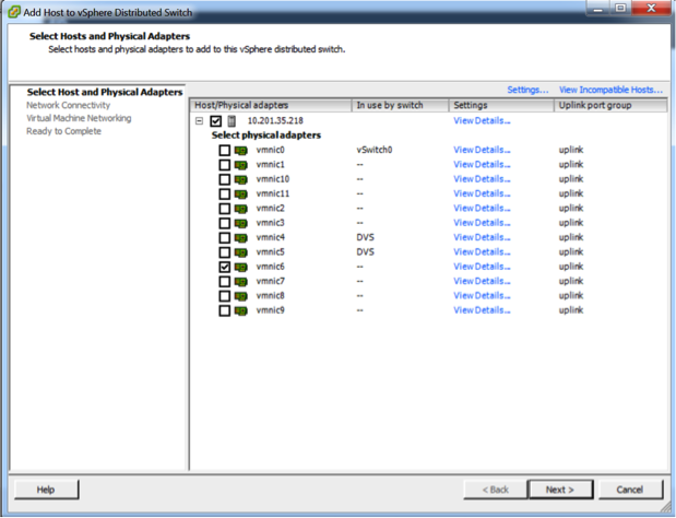
In the Add Host to vSphere Distributed Switch dialog box, choose the virtual NIC ports that are connected to the leaf switch (In this example you move only vmnic6), as shown in the image:
- Click Next
- In the Network Connectivity dialog box, click Next
- In the Virtual Machine Networking dialog box, click Next
- In the Ready to Complete dialog box, click Finish
Note: If multiple ESXi hosts are used, all of them need to run the AVS/VEM so they can be managed from Standard switch to DVS or AVS.
With this, AVS integration has been completed and we are ready to continue with L4-L7 ASAv deployment:
ASAv Initial Setup
- Download Cisco ASAv Device Package and import it into APIC:
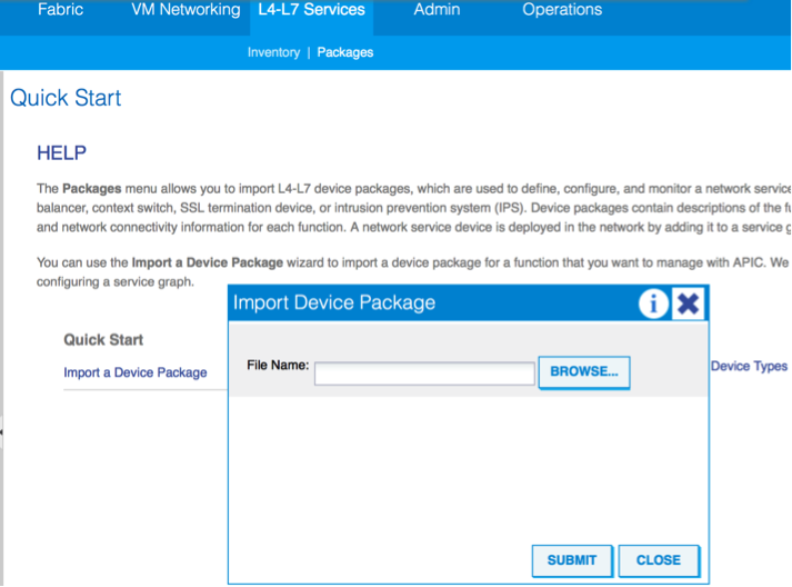
Navigate to L4-L7 Services > Packages > Import Device Package, as shown in the image:
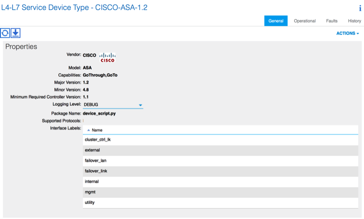
- If everything works well, you can see the imported device package expanding L4-L7 Service Device Types folder, as shown in the image:
Before you continue, there are few aspects of the installation that need to be determined before the actual L4-L7 integration is performed:
There are two types of Management networks, In-Band Management and Out-Of-Band (OOB), these can be used to manage devices that are not part of the basic Application Centric Infrastructure (ACI) (leaf, spines nor apic controller) which would include ASAv, Loadbalancers, etc.
In this case, OOB for ASAv is deployed with the use of Standard vSwitch. For bare metal ASA or other service appliances and/or servers, connect the OOB Management port to the OOB switch or Network, as shown in the image.
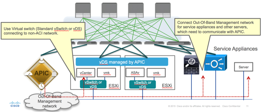
ASAv OOB Mgmt Port management connection needs to use ESXi uplink ports to communicate with APIC via OOB. When mapping vNIC interfaces, Network adapter1 always matches the Management0/0 interface on the ASAv, and the rest of the data plane interfaces are started from Network adapter2.
The Table 2 shows the concordance of Network Adapter IDs and ASAv interface IDs:
Table 2

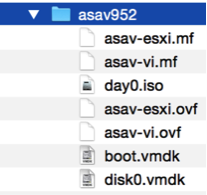
- Deploy the ASAv VM through the wizard from File>Deploy OVF (Open Virtualization Format) Template
- Select asav-esxi if you want to use standalone ESX Server or asav-vi for vCenter. In this case, vCenter is used.
- Go through the installation wizard, accept terms and conditions. In the middle of the wizard you can determine several options like hostname, management, ip address, firewall mode and other specific information related to ASAv. Remember to use OOB management for ASAv, as in this case you need to keep interface Management0/0 while you use the VM Network (Standard Switch) and interface GigabitEthernet0-8 is the default network ports.
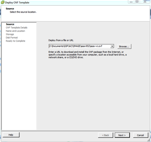
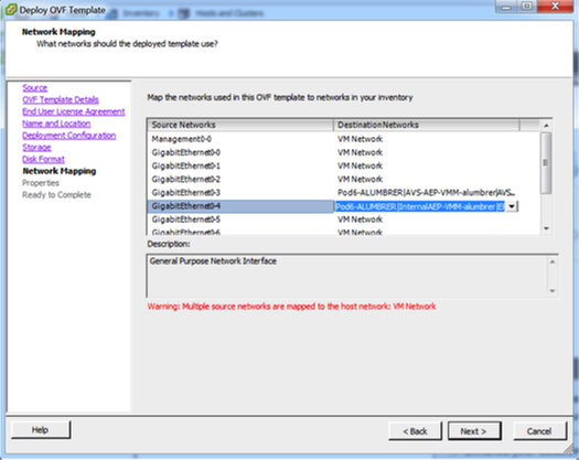


- Click Finish and wait until ASAv deployment is finished
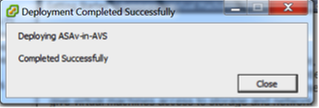
- Power On your ASAv VM and log in via console to verify initial configuration

- As shown in the image, some Management configuration is already pushed to the ASAv Firewall. Configure admin username and password. This username and password is used by the APIC to log in and configure the ASA. The ASA should have connectivity to the OOB network and should be able to reach the APIC.
username admin password <device_password> encrypted privilege 15

Additionally, from Global configuration mode enable http server:
http server enable
http 0.0.0.0 0.0.0.0 management
L4-L7 for ASAv Integration in APIC:
- Log in to the ACI GUI, click on the Tenant where the service graph will be deployed. Expand L4-L7 services at the bottom of the navigation pane and right click on L4-L7 Devices and click on Create L4-L7 devices to open the wizard
-
For this implementation, following settings will be applied:
-Managed Mode
-Firewall Service
-Virtual Device
-Connected to AVS domain with a Single Node
-ASAv Model
-Routed mode (GoTo)
-Management Address (has to match the previously address assigned to Mgmt0/0 interface)
- Use HTTPS as APIC by default uses the most secure protocol to communicate with ASAv
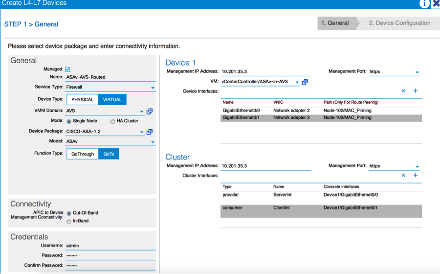
- The correct definition of the Device Interfaces and the Cluster Interfaces is critical for a successful deployment
For the first part, use Table 2 showed in the previous section to properly match the Network Adapter IDs with the ASAv interface IDs that you’d like to use. The Path refers to the physical Port or Port-channel or VPC that enables the way in and out of the Firewall interfaces. In this case, ASA is located in an ESX host, where in and out are same for both interfaces. In a Physical appliance, Inside and Outside of the Firewall (FW) would be different physical ports.
For the second part, the Cluster interfaces have to be defined always with not exceptions (even if Cluster HA is not used), this is because the Object Model has an association between the mIf interface (meta interface on the Device Package), the LIf interface (leaf interface such as e.g., external, internal, inside, etc.) and the CIf (concrete interface). The L4-L7 concrete devices have to be configured in a device cluster configuration and this abstraction is called a logical device. The logical device has logical interfaces that are mapped to concrete interfaces on the concrete device.
For this example, the following association will be used:
Gi0/0 = vmnic2 = ServerInt/provider/server > EPG1
Gi0/1 = vmnic3 = ClientInt/consumer/client > EPG2
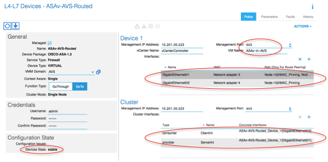
Note: For failover/HA deployments, GigabitEthernet 0/8 is pre-configured as the failover interface.
Device state should be Stable and you should be ready to deploy the Function Profile and Service Graph Template
Service Graph Temple
Firstly, create a Function Profile for ASAv but before that you need to create Function Profile Group and then L4-L7 Services Function Profile under that folder, as shown in the image:
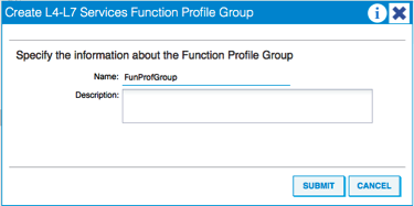
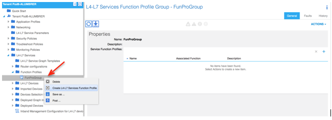
- Select the WebPolicyForRoutedMode Profile from the drop down menu and proceed to configure the interfaces on the firewall. From here on, the steps are optional and can be implemented/modified later. These steps can be taken at a few different stages in the deployment depending on how reusable or custom the Service Graph could be.
For this exercise, a routed firewall (GoTo mode) requires that each interface has a unique IP address. Standard ASA configuration also has a interface security level (external interface is less secure, internal interface is more secure). You can also change the name of the interface as per your requirement. Defaults are used in this example.
- Expand Interface Specific Configuration, add IP address and security level for ServerInt with the following format for the IP address x.x.x.x/y.y.y.y or x.x.x.x/yy. Repeat the process for the ClientInt interface.

Note: You can also modify the default Access-List settings and create your own base template. By default, the RoutedMode template will include rules for HTTP & HTTPS. For this exercise, SSH and ICMP will be added to the allowed outside access-list.

- Then click Submit
- Now, create the Service Graph Template
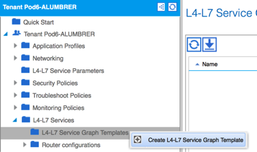
- Drag and Drop the Device Cluster to the right to form the relationship between Consumer and Provider, select Routed Mode and the previously created Function Profile.

- Check template for faults. The templates are created to be reusable, they must then be applied to particular EPGs etc.
- To apply a template, right click and select Apply L4-L7 Service Graph Template
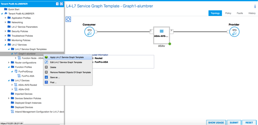
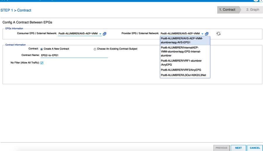
- Define which EPG will be on the Consumer side and Provider side. In this exercise, AVS-EPG2 is the Consumer (Client) and AVS-EPG1 is the Provider (server). Remember that no Filter is applied, this will allow the firewall to do all the filtering based on the access-list defined in the last section of this wizard.
- Click Next
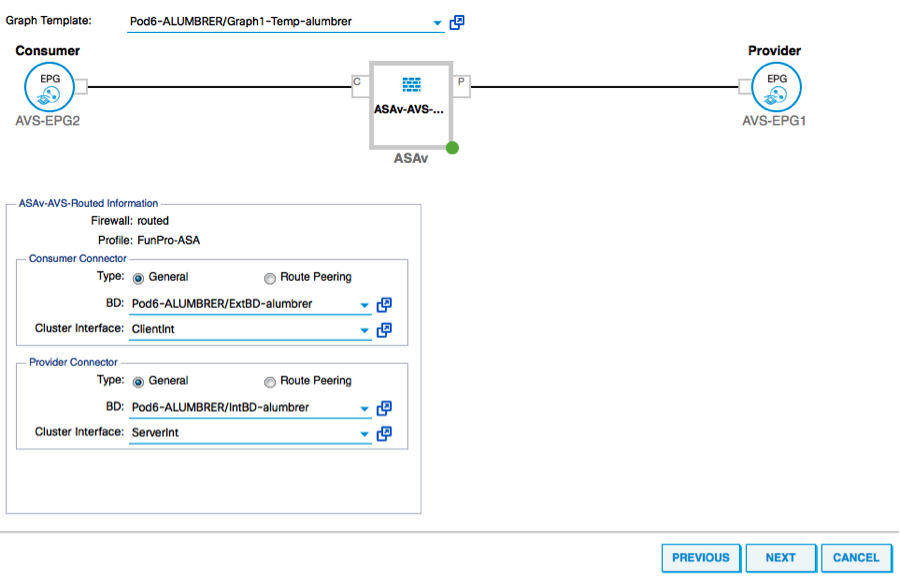
- Verify the BD information for each of the EPGs. In this case, EPG1 is the Provider on the IntBD DB and EPG2 is the Consumer on BD ExtBD. EPG1 will connect on firewall interface ServerInt and EPG2 will be connected on interface ClientInt. Both FW interfaces will become the DG for each of the EPGs so traffic is forced to cross the firewall at all times.
- Click Next
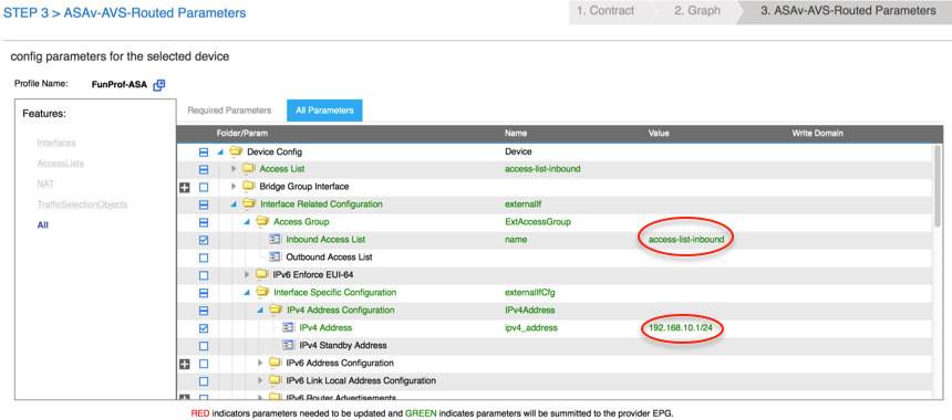
- In the Config Parameters section, click on All Parameters and verify if there are RED indicators that need to be updated/configured. In the output as shown in the image, it can be noticed that the order on the access-list is missed. This is equivalent to the line order you’ll see in a show ip access-list X.

- You can also verify the IP addressing assigned from the Function Profile defined earlier, here is a good chance to change information if required. Once all parameters are set, click Finish, as shown in the image:
- If everything goes fine, a new Deployed device and Graph Instance should appear.
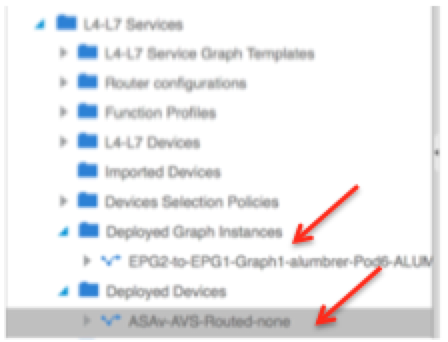
Verify
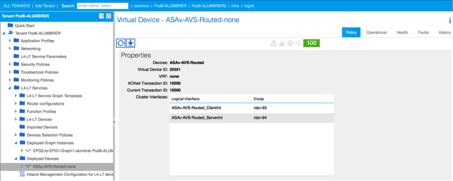
- One important thing to verify after creating the Service graph is that the Consumer/Provider relationship was created with proper Meta Connector. Verify under the Function Connector Properties.

Note: Each interface of the Firewall will be assigned with an encap-vlan from the AVS Dynamic Pool. Verify there are no faults.
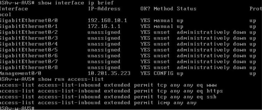
- Now, you can also verify the information that was pushed to the ASAv
- A new Contract is assigned under the EPGs. From now on, if you need to modify anything on the access-list, the change has to be done from the L4-L7 Service parameters of the Provider EPG.

- On vCenter, you can also verify the Shadow EPGs are assigned to each of the FW interfaces:
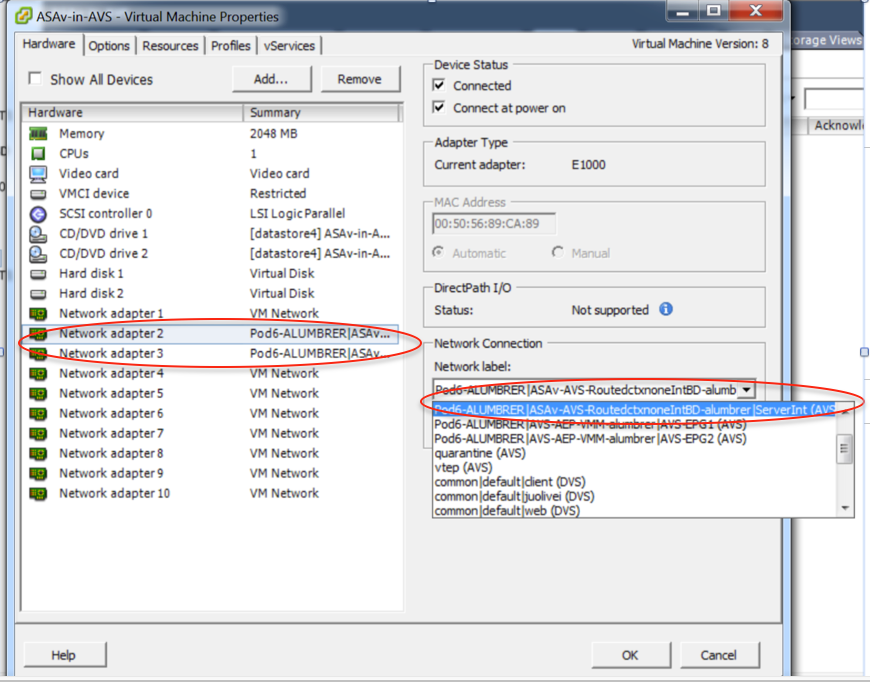
For this test, I had the 2 EPGs communicating with standard contracts, these 2 EPGs are in different Domains and different VRFs, so route leaking between them was previously configured. This simplifies a bit after your insert the Service Graph as the FW sets up the routing and filtering in between the 2 EPGs. The DG previously configured under the EPG and BD can now be removed same as the contracts. Only the contract pushed by the L4-L7 should remain under the EPGs.

As the standard contract is removed, you can confirm that traffic is now flows through the ASAv, the command show access-list should display the hit count for the rule incrementing every time the client sends a request to the server.

On the leaf, endpoints should be learned for client and server VMs as well as the ASAv interfaces
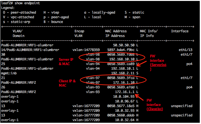
see both firewall interfaces attached to the VEM.
ESX-1

ESX-2

Finally, the Firewall rules can be verified at the leaf level too if we know the PC Tags for source and destination EPGs:
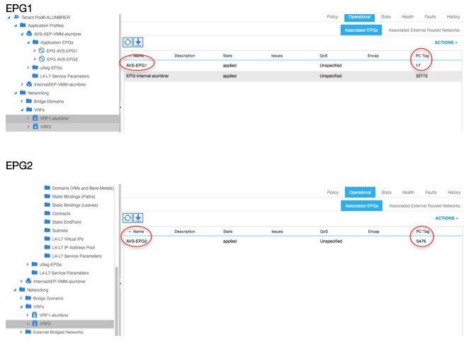
Filter IDs can be matched with the PC tags on the leaf to verify the FW rules.
Note: The EPG PCTags/Sclass never communicate directly. The communication is interrupted or tied together via the shadow EPGs created by the L4-L7 service graph insertion.
And communication Client to Server works.
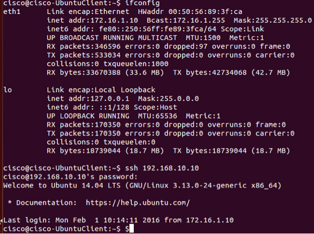

Troubleshoot
VTEP address is not assigned
Verify that Infrastructure Vlan is checked under the AEP:
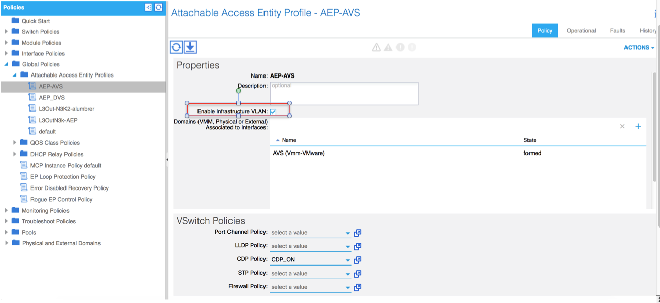
Unsupported Version
Verify VEM version is correct and support appropriate ESXi VMWare system.
~ # vem version
Running esx version -1746974 x86_64
VEM Version: 5.2.1.3.1.10.0-3.2.1
OpFlex SDK Version: 1.2(1i)
System Version: VMware ESXi 5.5.0 Releasebuild-1746974
ESX Version Update Level: 0
[an error occurred while processing this directive]
VEM and Fabric communication not working
- Check VEM status vem status - Try reloading or restating the VEM at the host: vem reload vem restart - Check if there’s connectivity towards the Fabric. You can try pinging 10.0.0.30 which is (infra:default) with 10.0.0.30 (shared address, for both Leafs) ~ # vmkping -I vmk1 10.0.0.30 PING 10.0.0.30 (10.0.0.30): 56 data bytes --- 10.0.0.30 ping statistics --- 3 packets transmitted, 0 packets received, 100% packet loss If ping fails, check: - Check OpFlex status - The DPA (DataPathAgent) handles all the control traffic between AVS and APIC (talks to the immediate Leaf switch that is connecting to) using OpFlex (opflex client/agent).[an error occurred while processing this directive]
All EPG communication will go thru this opflex connection. ~ # vemcmd show opflex Status: 0 (Discovering) Channel0: 0 (Discovering), Channel1: 0 (Discovering) Dvs name: comp/prov-VMware/ctrlr-[AVS]-vCenterController/sw-dvs-129 Remote IP: 10.0.0.30 Port: 8000 Infra vlan: 3967 FTEP IP: 10.0.0.32 Switching Mode: unknown Encap Type: unknown NS GIPO: 0.0.0.0 you can also check the status of the vmnics at the host level: ~ # esxcfg-vmknic -l Interface Port Group/DVPort IP Family IP Address Netmask Broadcast MAC Address MTU TSO MSS Enabled Type vmk0 Management Network IPv4 10.201.35.219 255.255.255.0 10.201.35.255 e4:aa:5d:ad:06:3e 1500 65535 true STATIC vmk0 Management Network IPv6 fe80::e6aa:5dff:fead:63e 64 e4:aa:5d:ad:06:3e 1500 65535 true STATIC, PREFERRED vmk1 160 IPv4 10.0.32.65 255.255.0.0 10.0.255.255 00:50:56:6b:ca:25 1500 65535 true STATIC vmk1 160 IPv6 fe80::250:56ff:fe6b:ca25 64 00:50:56:6b:ca:25 1500 65535 true STATIC, PREFERRED ~ # - Also on the host, verify if DHCP requests are sent back and forth: ~ # tcpdump-uw -i vmk1 tcpdump-uw: verbose output suppressed, use -v or -vv for full protocol decode listening on vmk1, link-type EN10MB (Ethernet), capture size 96 bytes 12:46:08.818776 IP truncated-ip - 246 bytes missing! 0.0.0.0.bootpc > 255.255.255.255.bootps: BOOTP/DHCP, Request from 00:50:56:6b:ca:25 (oui Unknown), length 300 12:46:13.002342 IP truncated-ip - 246 bytes missing! 0.0.0.0.bootpc > 255.255.255.255.bootps: BOOTP/DHCP, Request from 00:50:56:6b:ca:25 (oui Unknown), length 300 12:46:21.002532 IP truncated-ip - 246 bytes missing! 0.0.0.0.bootpc > 255.255.255.255.bootps: BOOTP/DHCP, Request from 00:50:56:6b:ca:25 (oui Unknown), length 300 12:46:30.002753 IP truncated-ip - 246 bytes missing! 0.0.0.0.bootpc > 255.255.255.255.bootps: BOOTP/DHCP, Request from 00:50:56:6b:ca:25 (oui Unknown), length 300
At this point it can be determined that Fabric communication between the ESXi host and the Leaf does not work properly. Some verification commands can be checked at the leaf side to determine root cause.
leaf2# show cdp ne

Capability Codes: R - Router, T - Trans-Bridge, B - Source-Route-Bridge
                  S - Switch, H - Host, I - IGMP, r - Repeater,
                  V - VoIP-Phone, D - Remotely-Managed-Device,
                  s - Supports-STP-Dispute

Device-ID          Local Intrfce  Hldtme  Capability  Platform      Port ID
AVS:localhost.localdomainmain
                     Eth1/5          169     S I s      VMware ESXi    vmnic4
AVS:localhost.localdomainmain
                     Eth1/6          169     S I s      VMware ESXi    vmnic5
N3K-2(FOC1938R02L)
                     Eth1/13         166     R S I s    N3K-C3172PQ-1  Eth1/13

leaf2# show port-c sum
Flags:  D - Down        P - Up in port-channel (members)
        I - Individual  H - Hot-standby (LACP only)
        s - Suspended   r - Module-removed
        S - Switched    R - Routed
        U - Up (port-channel)
        M - Not in use. Min-links not met
        F - Configuration failed
-------------------------------------------------------------------------------
Group Port-       Type     Protocol  Member Ports
      Channel
-------------------------------------------------------------------------------
5     Po5(SU)     Eth      LACP      Eth1/5(P)    Eth1/6(P)
[an error occurred while processing this directive]
There are 2 Ports used in the ESXi connected via a Po5
leaf2# show vlan extended

 VLAN Name                             Status    Ports
 ---- -------------------------------- --------- -------------------------------
 13   infra:default                    active    Eth1/1, Eth1/20
 19   --                               active    Eth1/13
 22   mgmt:inb                         active    Eth1/1
 26   --                               active    Eth1/5, Eth1/6, Po5
 27   --                               active    Eth1/1
 28   ::                               active    Eth1/5, Eth1/6, Po5
 36   common:pod6_BD                   active    Eth1/5, Eth1/6, Po5

 VLAN Type  Vlan-mode  Encap
 ---- ----- ---------- -------------------------------
 13   enet  CE         vxlan-16777209, vlan-3967
 19   enet  CE         vxlan-14680064, vlan-150
 22   enet  CE         vxlan-16383902
 26   enet  CE         vxlan-15531929, vlan-200
 27   enet  CE         vlan-11
 28   enet  CE         vlan-14
 36   enet  CE         vxlan-15662984
[an error occurred while processing this directive] From the above output it can be observed that the Infra Vlan is not allowed or passed through the Uplinks ports that go to the ESXi host (1/5-6). This indicates a misconfiguration with the Interface Policy or Switch Policy configured on APIC.
Check both:
Access Policies > Interface Policies > Profiles Access Policies > Switch Policies > Profiles
In this case, the interface profiles are attached to the wrong AEP (old AEP used for DVS), as shown in the image:
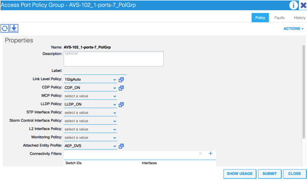
After setting of the correct AEP for AVS, we can now see that the Infra Vlan is seen thru the proper Unlinks at the Leaf:
leaf2# show vlan extended

 VLAN Name                             Status    Ports
 ---- -------------------------------- --------- -------------------------------
 13   infra:default                    active    Eth1/1, Eth1/5, Eth1/6,
                                                 Eth1/20, Po5
 19   --                               active    Eth1/13
 22   mgmt:inb                         active    Eth1/1
 26   --                               active    Eth1/5, Eth1/6, Po5
 27   --                               active    Eth1/1
 28   ::                               active    Eth1/5, Eth1/6, Po5
 36   common:pod6_BD                   active    Eth1/5, Eth1/6, Po5

 VLAN Type  Vlan-mode  Encap
 ---- ----- ---------- -------------------------------
 13   enet  CE         vxlan-16777209, vlan-3967
 19   enet  CE         vxlan-14680064, vlan-150
 22   enet  CE         vxlan-16383902
 26   enet  CE         vxlan-15531929, vlan-200
 27   enet  CE         vlan-11
 28   enet  CE         vlan-14
 36   enet  CE         vxlan-15662984

and Opflex connection is restablised after restarting the VEM module:

~ # vem restart
stopDpa
VEM SwISCSI PID is
Warn: DPA running host/vim/vimuser/cisco/vem/vemdpa.213997
Warn: DPA running host/vim/vimuser/cisco/vem/vemdpa.213997
watchdog-vemdpa: Terminating watchdog process with PID 213974

~ # vemcmd show opflex
Status: 0 (Discovering)
Channel0: 14 (Connection attempt), Channel1: 0 (Discovering)
Dvs name: comp/prov-VMware/ctrlr-[AVS]-vCenterController/sw-dvs-129
Remote IP: 10.0.0.30 Port: 8000
Infra vlan: 3967
FTEP IP: 10.0.0.32
Switching Mode: unknown
Encap Type: unknown
NS GIPO: 0.0.0.0

~ # vemcmd show opflex
Status: 12 (Active)
Channel0: 12 (Active), Channel1: 0 (Discovering)
Dvs name: comp/prov-VMware/ctrlr-[AVS]-vCenterController/sw-dvs-129
Remote IP: 10.0.0.30 Port: 8000
Infra vlan: 3967
FTEP IP: 10.0.0.32
Switching Mode: LS
Encap Type: unknown
NS GIPO: 0.0.0.0
[an error occurred while processing this directive]
Related Information
Application Virtual Switch Installation
Cisco Systems, Inc. Cisco Application Virtual Switch Installation Guide, Release 5.2(1)SV3(1.2)Deploy the ASAv Using VMware
Cisco Systems, Inc. Cisco Adaptive Security Virtual Appliance (ASAv) Quick Start Guide, 9.4
Cisco ACI and Cisco AVS
Cisco Systems, Inc. Cisco ACI Virtualization Guide, Release 1.2(1i)
Service Graph Design with Cisco Application Centric Infrastructure White Paper
Service Graph Design with Cisco Application Centric Infrastructure White Paper
Contributed by Cisco Engineers
- Aida LumbrerasCisco Advanced Services Engineer
Contact Cisco
- Open a Support Case

- (Requires a Cisco Service Contract)

 Feedback