Introduction
This document describes the configuration steps that are required in order to integrate a Cisco Unified Computing System (UCS) B Series into an Application Centric Infrastructure (ACI) fabric that leverages Virtual Machine Manager (VMM) domain integration.
Prerequisites
Requirements
There are no specific requirements for this document.
Components Used
The information in this document is based on these hardware and software versions:
- An ACI fabric that consists of two spine switches and two leaf switches
- A UCS B Series chassis with two fabric interconnects
- UCS B Series blades with VMware ESXi
- An Application Policy Infrastructure Controller (APIC)
The information in this document was created from the devices in a specific lab environment. All of the devices used in this document started with a cleared (default) configuration. If your network is live, make sure that you understand the potential impact of any command.
Configure
Create the VMM Domain
Most of this configuration is similar to the deployment of a VMM domain on any server hardware. There are certain limitations for which the workaround is to configure the APIC a certain way. These workaround configurations are called out specifically in this procedure.
- Create a dynamic VLAN pool. From the APIC user interface, choose Fabric > Access Policies > Pools > VLAN > Create VLAN Pool.
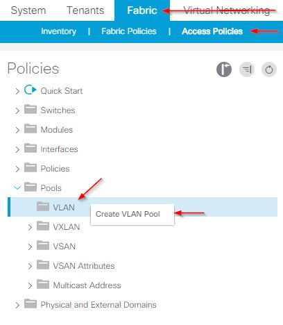
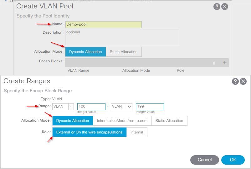
- When the Create VLAN Pool window opens, enter this information:
- Enter the name of the pool in the Name field.
- Click Dynamic Allocation.
- Click the Encap Blocks (+) plus symbol and enter the Encap Block Range in the Range fields of the Create Ranges dialog box.
- Click Dynamic Allocation for the Allocation Mode field.
- Click External or On the wire encapsulations.
- Click OK.
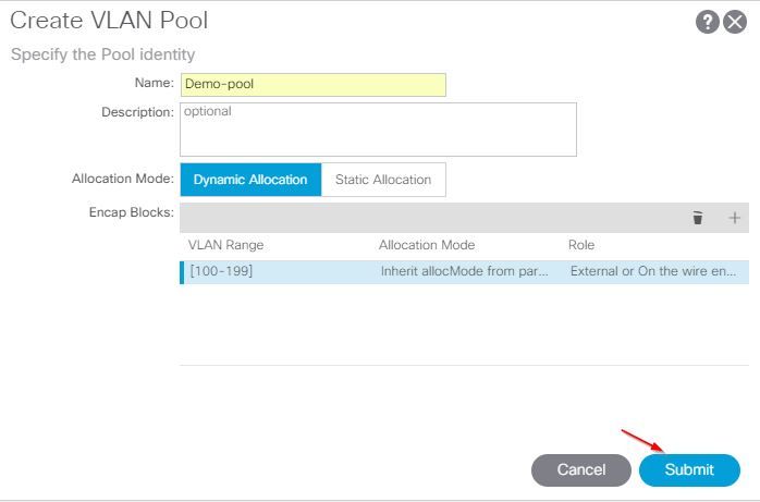
- Click Submit.
- From the APIC user interface, choose Virtual Networking > VMM Domains > VMware > Create vCenter Domain.
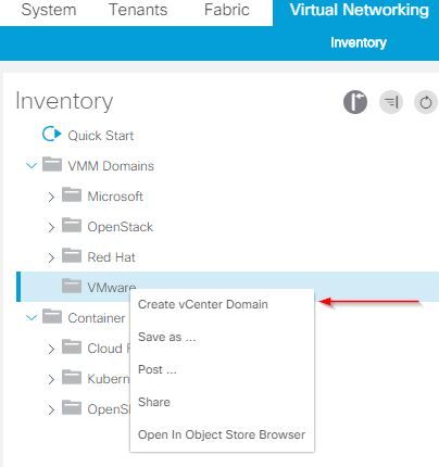
- When the Create vCenter Domain window appears, enter this information:
- Enter the domain name in the Virtual Switch Name field.
- Click VMWare vSphere Distributed Switch.
- Choose (create if needed) Demo-AEP from the Associated Attachable Entity Profile drop-down list.
- Choose Demo-Pool (dynamic) from the VLAN Pool drop-down list.
- Click the vCenter Credentials (+) plus symbol and enter your vCenter Credential information in the Create vCenter Credential dialog box.
- Click OK.
- Click Submit.
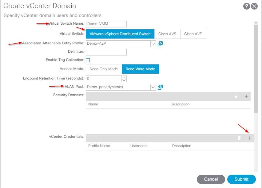
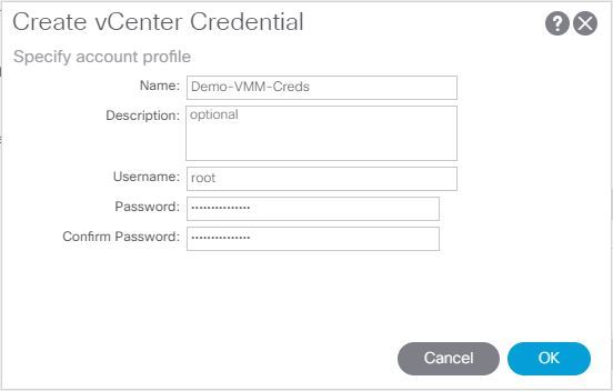
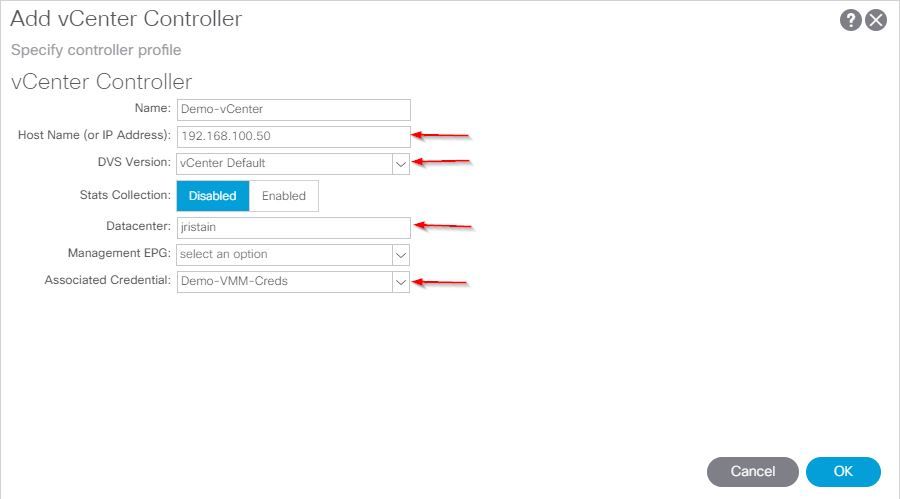
- Click the (+) plus symbol by vCenter heading from the Create vCenter Domain window, it may be required to scroll down to see it. Enter this information when the Create vCenter Controller window appears:

- Enter the host name or IP address in the Host Name (or IP Address) field.
- Choose vCenter Default from the DVS Version drop-down list.
- Enter the name of the datacenter in the Datacenter field.
- Choose Demo-VMM-Creds from the Associated Credential drop-down list.
- Click OK.
- Click Submit.
Verify the DVS is Created in vCenter
You should see a few new tasks in the Recent Tasks window and the addition of a Distributed Virtual Switch (DVS) in the vCenter Server:


Create/Verify that CDP or LLDP is Enabled on the UCS vNICs
When you deploy UCS B in ACI, you can choose the discovery protocol you would like to use to discover the hosts. This section walks you through how to configure each type in the UCS Manager.
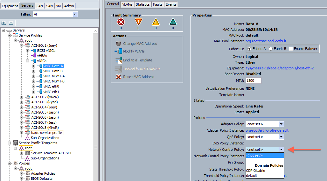
By default, Cisco Discovery Protocol (CDP) is disabled on the UCS virtual Network Interface Card (vNIC) because the default Network Control Policy has CDP disabled. In order to enable CDP, you can either modify the default Network Control Policy, or create a new one with CDP enabled. Then apply that policy to each vNIC in each Service Profile. In this example, the default Network Control Policy is modified since all of the Service Profiles use that by default:
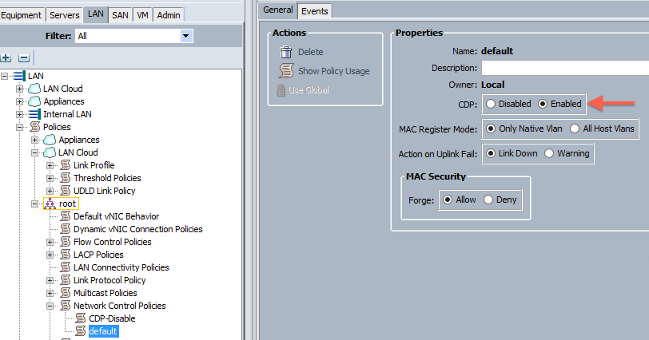
If you use a different policy, ensure you add that policy to the vNICs in each Service Profile:
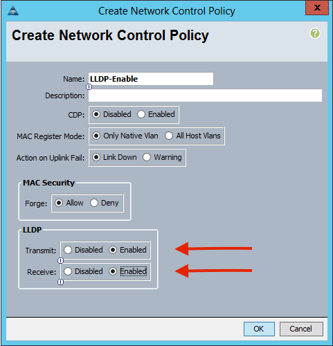
In Version 2.2(4b) and later, the UCS supports Link Layer Discovery Protocol (LLDP) from the Fabric Interconnects down to the blades. This means that you can also use LLDP in order to discover the hosts in vCenter and the fabric if you run this version or later. The configuration is the exact same as above, but you would enable LLDP in both directions:
Configure the vSwitch Policies on APIC for UCS B
By default on the DVS, the Discovery Protocol used is LLDP. This is fine for any servers that support LLDP, but the UCS B series blades only support LLDP on UCSM version 2.2(4b) and later. Because of this, ESXi cannot report LLDP information to the APIC, unless you are on the correct code.
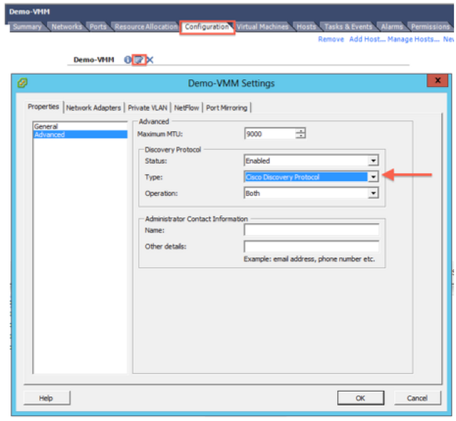
As an alternative to LLDP, use CDP in order to discover the hosts. In order to get the DVS to use CDP, configure a vSwitch policy on the VMM Domain that has CDP enabled and LLDP disabled.
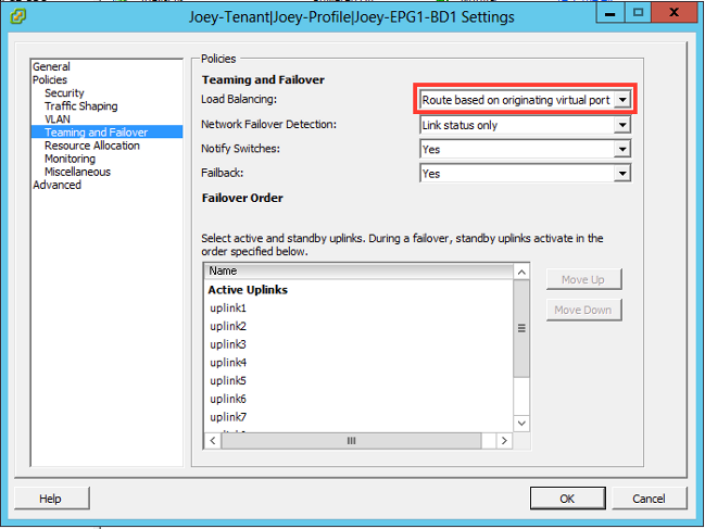
Along with this, the only supported load balancing mechanism when UCS B series is used is Route Based on Originating Virtual Port. If you configure a mac-pinning policy, it programs the port groups to use this mechanism. This is very important in order to prevent packet loss.
- From the APIC user interface, choose Virtual Networking > VMM Domains > VMware > Configured Domain > Create VSwitch Policies.
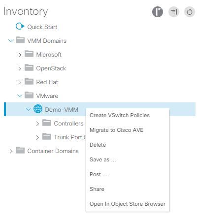
- At this point, a warning will be displayed to alert you that a default VSwitch policy has been created.
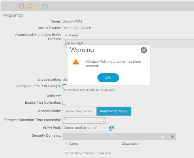
- Accept the warning message and navigate to the Vswitch Policy tab under the VMM Domain:
- Choose or create a CDP Policy where CDP is enabled.
- Choose or create a Port Channel Policy with mac-pinning mode selected.
- Choose or create an LLDP Policy where CDP is disabled.
- Click Submit.
Note: If you are on UCSM 2.2(4b) or later, and you want to use LLDP, you can turn on LLDP in this vSwitch policy since the UCS supports it. This example is only for UCSM versions that do not support LLDP, or if CDP is desired. If both LLDP and CDP are enabled, LLDP takes priority.

After you click Submit, you can see that the DVS is reconfigured in the vCenter:
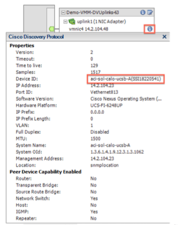
You can also verify that the vmnics see CDP information from the Fabric Interconnect:
- Verify that "Route based on originating virtual port" is programmed on the port groups. Right-click a port group in the Networking tab, and edit the setting in order to verify this:
Verify
Use this section to confirm that your configuration works properly.
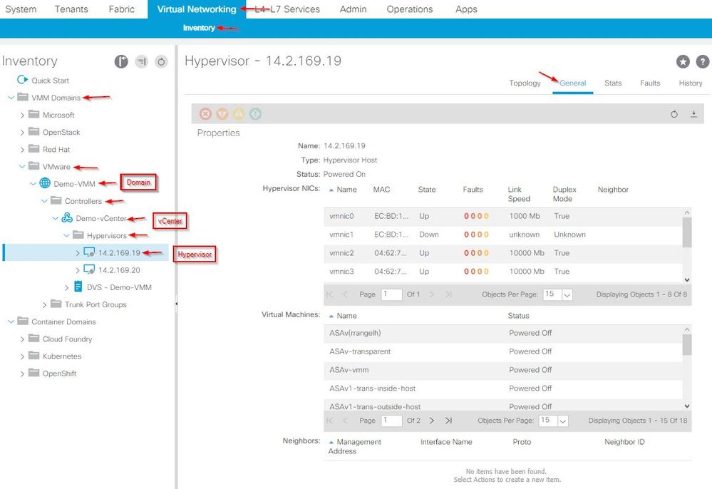
After these changes are made, the APIC should be notified by the vCenter about the CDP information. In order to verify this, check the inventory of the VMM domain.
From the APIC user interface, choose Virtual Networking > Inventory > VMM Domains > VMware > Domain > Controllers > vCenter > Hypervisors > Hypervisor > General in order to view the Properties window.
At this point, you can change your VM Network settings to add the adapter to the proper port group and test connectivity. Pings should be successful. If pings are not successful, verify all settings in vCenter and in the APIC are correct for CDP neighbor discovery.
Troubleshoot
There is currently no specific troubleshooting information available for this configuration.


 Feedback