Why Do Some Cable Modems Display a Negative Time Offset?
Available Languages
Contents
Introduction
The Time Offset of a Cable Modem, also known as the Ranging Offset, is a value indicating the round trip delay between a Cable Modem Termination System (CMTS) and a connected Cable Modem. This value is calculated by the CMTS and the Cable Modem as a part of the Initial Ranging Process when a Cable Modem comes online. It is important for a CMTS and Cable Modem to have an accurate idea of the correct time offset so that upstream transmissions from Cable Modems are properly synchronized when they arrive at the CMTS at the appropriate time.
Some Cable Modems may violate certain parts of the DOCSIS specification when performing initial ranging and may produce a Negative Time Offset or a Time Offset that is significantly smaller than the real value. When a cable modem shows zero, or negative timing offsets it is non fully DOCSIS compliant and results from the modem improperly caching the last used timing offset, going offline, and then re-using that timing offset when re-establishing registration. The causes of this problem and recommended courses of action are described in this document. It is important to note that the cause of the problem is due to the behavior of the Cable Modem and not the CMTS.
Most of the harmful impact of the problem can be worked around by configuring the cable interface command cable map-advance static on the CMTS, however the Cable Modem vendor is responsible for actually fixing the negative timing offset issue by supplying newer revisions of Cable Modem firmware.
Prerequisites
Requirements
Reader must have some basic knowledge of DOCSIS with respects to the ranging process that cable modems must complete in order to connect to a CMTS.
Components Used
This document is not restricted to specific software and hardware versions.
How the Time Offset Is Calculated
The time offset, which is an indication of the round trip delay between a CMTS and Cable Modem, is normally determined by four major factors:
-
The physical distance of the Cable Modem from the CMTS
-
The Downstream Modulation Scheme and interleave depth
-
The Upstream Modulation Scheme and channel width
-
The Model of Cable Modem and firmware
You may view the time offset value for a particular cable modem by executing the show cable modem command on the CMTS that it is connected to. Here is an example output from this command in a typical system.
CMTS# show cable modem
Interface   Prim Online     Timing Rec    QoS CPE IP address      MAC address
            Sid  State      Offset Power
Cable3/0/U0 2    online     3011    0.75  5   0   10.1.1.52       0001.9659.4461
Cable3/0/U0 3    online     2647    0.50  7   0   10.1.1.40       0001.9659.5370
Cable3/0/U0 4    online     3011    0.25  5   0   10.1.1.48       0001.9659.4415
Cable3/0/U0 5    online     3007    0.25  6   0   10.1.1.11       0001.9659.43fd
The Time Offset is quoted in units of 1/64th of a DOCSIS tick. A tick is defined as 6.25 microseconds which makes one Time Offset unit equal to 97.65625 nanoseconds.
The Time Offset is calculated as a part of the Initial Ranging process that cable modems must complete in order to connect to a CMTS. The parts of the Initial Ranging process where the Time Offset is derived is shown in Figure 1 below. Note that this figure misses a few components of the Initial Ranging not relevant to this document.
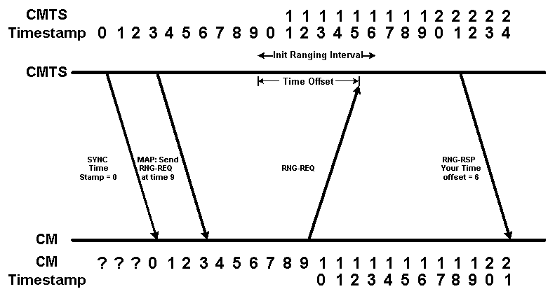
Figure 1
In Figure 1 we have two timelines. The top timeline shows the system timestamp according to the CMTS. The bottom timeline shows the system timestamp according to the Cable Modem. For the sake of simplicity we start this time line at 0 and we use imaginary time units. Note that at first the Cable Modem does not know what the system timestamp is.
The Cable Modem must wait to hear a SYNC message sent by the CMTS with the correct system timestamp before it knows what the current timestamp is. Note that due to the propagation delay encountered by the SYNC message, by the time the Cable Modem hears the SYNC message stating that the system timestamp is 0, the CMTS's timestamp has increased to 3.
The next message in the diagram is a MAP message which commands the Cable Modem to send an Initial Ranging Request at timestamp 9. Since the Cable Modem does not know when timestamp 9 occurs on the CMTS, it must send the Initial Ranging Request at timestamp 9 according to it's own clock.
The CMTS expects that Initial Ranging requests could arrive at any time between CMTS timestamp 9 and 16. This time allocated to receive Initial Ranging Requests is called the Initial Ranging Interval, and needs to be large enough to accommodate the propagation delay between the CMTS and a Cable Modem at the furthest point in the cable plant.
The Cable Modem sends its Initial Ranging Request when its internal timestamp is "9" but by the time the Initial Ranging Request gets to the CMTS, the CMTS's timestamp is 15. This means that the CMTS can calculate the Time Offset of this Cable Modem to be 15 - 9 = 6 units.
The CMTS communicates this Time Offset value to the Cable Modem by sending a Ranging Response message. Once the Cable Modem receives this message it is able to add the appropriate time offset to any future messages sent to the CMTS.
In Figure 2 below we see that from now on, when the CMTS commands the Cable Modem to transmit some data at a particular timestamp, the modem takes the Time Offset into account. In the figure, a MAP message is sent from the CMTS to the Cable Modem commanding it to transmit some data at Timestamp 70. When the Cable Modem takes the Time Offset of 6 into account this means that the Cable Modem transmits it's data at timestamp 70 - 6 = 64. Note that the transmission arrives at the CMTS at timestamp 70.
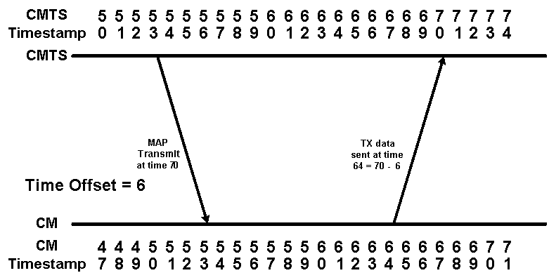
Figure 2
The Behavior of a Cable Modem Exhibiting the Negative Time Offset Problem
When a Cable Modem transitions from the online state to the offline state for any reason, it must re-perform Initial Ranging in order to re-connect to the CMTS. Some cable modems "cheat" during this process by remembering their original timing offset when they come online for the second time. Even though one might think that the cheating speeds up the initial ranging time, in reality this cannot improve the time it takes for the modem to return to the online status. In fact, if the Initial Ranging packet arrives too "early" for the CMTS, data from another modem will be lost, and the CM attempting to re-connect will not be successful. If the initial ranging packet arrives at exactly the start of the ranging opportunity, the CMTS sees a time offset of zero, but does not provide any better opportunity to connect.
This section deals with the details of how these cable modems violate the DOCSIS spec when coming online.
Figure 3 shows the sequence of events when a modem remembers its original time offset when performing Initial Ranging. In this diagram we assume that the propagation delay between the CMTS and the Cable Modem is unchanged between the time that the modem goes offline and then attempts to come online again.
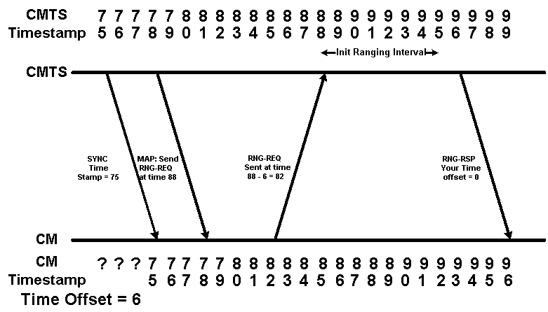
Figure 3
In the diagram, the Cable Modem is told to send an Initial Ranging Request at timestamp 88. Since the Cable Modem remembers its previous time offset, it decides to send the Ranging Request at time 88 - 6 = 82. This means that the Initial Ranging Request from the Cable Modem arrives at the CMTS at timestamp 88. The CMTS will therefore think that the time offset for this cable modem is zero. In the following show cable modem output the modem with MAC address 00ff.de4d.b3ef is exhibiting this kind of behavior.
CMTS# show cable modem
Interface   Prim Online     Timing Rec    QoS CPE IP address      MAC address
            Sid  State      Offset Power
Cable3/0/U0 2    online     3011    0.75  5   0   10.1.1.52       0001.9659.4461
Cable3/0/U0 3    online     2647    0.50  7   0   10.1.1.40       0020.4001.5370
Cable3/0/U0 4    online        0    0.00  5   0   10.1.1.57       00ff.de4d.b3ef
Cable3/0/U0 5    online     3011    0.25  5   0   10.1.1.48       0001.9659.4415
As we know, the propagation delay or latency of the HFC network is defined as the speed of light through the fiber and coax distance from the CMTS to Modem and back. This speed is temperature dependent, and over long distances typical in an HFC network, and very fine timing resolution, is subject to vary by hundreds of time ticks per day. If the propagation delay or latency of either the upstream or downstream path changes between the time that the modem goes offline and then attempts to come online again, the time offset that the modem remembers will be invalid. If the propagation delay increases then the order of events when the modem comes back on line may look like those shown in Figure 4.
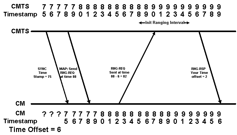
Figure 4
In Figure 4 the CMTS believes that the Cable Modem's timing offset is 2. This represents the real life scenario where the timing offset reported in a show cable modem output displays a time less than the minimum possible round trip time. If a Cable Modem reports a timing offset of significantly less than 1000 then it may be behaving like the Cable Modem in Figure 4. In the following show cable modem output the modem with MAC address 00ff.de4d.b3ef is exhibiting this kind of behavior.
CMTS# show cable modem
Interface   Prim Online     Timing Rec    QoS CPE IP address      MAC address
            Sid  State      Offset Power
Cable3/0/U0 2    online     3011    0.75  5   0   10.1.1.52       0001.9659.4461
Cable3/0/U0 3    online     2647    0.50  7   0   10.1.1.40       0020.4001.5370
Cable3/0/U0 4    online       35    0.00  5   0   10.1.1.57       00ff.de4d.b3ef
Cable3/0/U0 5    online     3011    0.25  5   0   10.1.1.48       0001.9659.4415
Another potential case is where the propagation delay of the path between the CMTS and Cable Modem decreases slightly between the time that the modem goes offline and then attempts to come online again. This is shown in Figure 5.
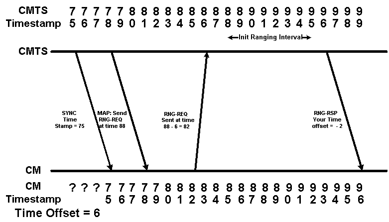
Figure 5
In Figure 5 the Cable Modem's Ranging Request is received by the CMTS at timestamp 86 which is 2 units before the Initial Ranging Interval begins. Assuming that the CMTS is still able to receive and interpret this Ranging Request, the CMTS will think that the Cable Modem's timing offset is negative 2. This represents the real life scenario where the timing offset reported in a show cable modem output is a negative number. In the following show cable modem output the modem with MAC address 00ff.de4d.b3ef is exhibiting this kind of behavior.
CMTS# show cable modem
Interface   Prim Online     Timing Rec    QoS CPE IP address      MAC address
            Sid  State      Offset Power
Cable3/0/U0 2    online     3011    0.75  5   0   10.1.1.52       0001.9659.4461
Cable3/0/U0 3    online     2647    0.50  7   0   10.1.1.40       0020.4001.5370
Cable3/0/U0 4    online      -93    0.00  5   0   10.1.1.57       00ff.de4d.b3ef
Cable3/0/U0 5    online     3011    0.25  5   0   10.1.1.48       0001.9659.4415
The Problems Caused by an Invalid Time Offset - Dynamic Map Advance
The major problem caused by modems which generate a negative or invalid time offset is the disruption to the Dynamic Map-Advance algorithm that is enabled by default on Cisco CMTS products running Cisco IOS® software releases later than 12.0(9)SC, 12.1(2)EC1, 12.1(1a) and 12.1(1a)T.
The Dynamic Map Advance algorithm significantly enhances upstream performance for cable modems by dynamically determining the time offset of the furthest Cable Modem from the CMTS. By using this information, the CMTS is able to reduce the delay between the Cable Modem making requests for upstream bandwidth and the time when the CMTS actually allocates this bandwidth to a cable modem.
Video: Dynamic Map Advance Algorithm
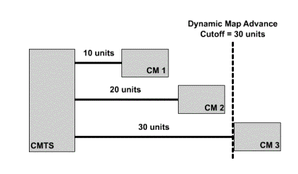
Figure 6 shows how the Dynamic Map Advance algorithm uses the maximum timing offset. The round trip delay for each cable modem is shown in the diagram. By looking at the time offset reported for each modem, the CMTS is able to calculate the time offset of the furthest modem.
Click Figure 6 to see how the Dynamic Map Advance algorithm uses the maximum timing offset.
If the furthest cable modem from the CMTS exhibits the negative time offset problem, then the CMTS will believe that this cable modem is closer to the CMTS than it really is. Put another way, the Time Offset for this modem in the show cable modem output will be much smaller than it really is. This means that the modem's true distance from the CMTS will not be correctly taken into account when the Dynamic Map-Advance algorithm is calculating the maximum round trip delay for all cable modems. This will lead to connectivity problems for this furthest modem.
Figure 7 shows the situation where the furthest cable modem in a system has an incorrect time offset. Even though the furthest modem's real time offset is 30, it's reported time offset is -2. This means that the dynamic map-advance algorithm will believe that the furthest modem in the system is the one with time offset 20. This will place the furthest modem in the system beyond the Dynamic Map Advance Cutoff point.
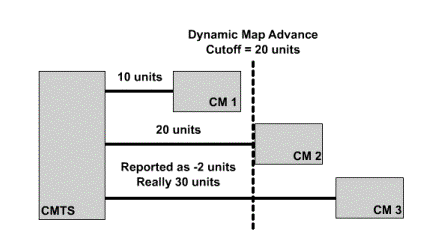
Click here to see Figure 7 as a video.
Versions of Cisco IOS software later than 12.0(10)SC, 12.1(2)EC1, 12.1(2) and 12.1(2)T have a mechanism within them that protect the Dynamic Map Advance algorithm from cable modems with negative time offsets. When a cable modem comes online with a negative time offset the CMTS will log an error message of the form:
%UBR7200-4-BADTXOFFSET: Bad timing offset -2 detected for cable modem 00ff.0bad.caf3
If this message appears on your CMTS you should contact the modem vendor and ask for a version of firmware that does not exhibit the problem.
In order to ensure that Cable Modems exhibiting the negative time offset problem maintain connectivity, it may be necessary to turn off the dynamic map-advance algorithm until all cable modems connected to the CMTS are running DOCSIS compliant firmware. In order to disable dynamic map advance on a particular downstream port enter the following commands on your CMTS.
CMTS# conf t
Enter configuration commands, one per line.  End with CNTL/Z.
CMTS(config)# interface cable 3/0
!--Specify the Cable interface affected

CMTS(config-if)# cable map-advance static
CMTS(config-if)# end
CMTS#
In order to confirm that dynamic map advance has been turned off look for the line Map Advance (Static) in the output of a show controller cable X/Y upstream Z where X/Y is the cable downstream port number and Z is an active upstream port.
CMTS# show controller cable 3/0 upstream 0
 Cable3/0 Upstream 0 is up
  Frequency 25.008 MHz, Channel Width 1.600 MHz, QPSK Symbol Rate 1.280 Msps
  Spectrum Group is overridden
  SNR 33.640 dB
  Nominal Input Power Level 1 dBmV, Tx Timing Offset 2817
  Ranging Backoff automatic (Start 0, End 3)
  Ranging Insertion Interval automatic (60 ms)
  Tx Backoff Start 0, Tx Backoff End 4
  Modulation Profile Group 1
  Concatenation is enabled
  part_id=0x3137, rev_id=0x03, rev2_id=0xFF
  nb_agc_thr=0x0000, nb_agc_nom=0x0000
  Range Load Reg Size=0x58
  Request Load Reg Size=0x0E
  Minislot Size in number of Timebase Ticks is = 8
  Minislot Size in Symbols = 64
  Bandwidth Requests = 0x2F
  Piggyback Requests = 0x22
  Invalid BW Requests= 0x0
  Minislots Requested= 0x50D
  Minislots Granted  = 0x50D
  Minislot Size in Bytes = 16
  Map Advance (Static) : 3480 usecs
  UCD Count = 122
  DES Ctrl Reg#0 = C000C043, Reg#1 = 0
Note that once dynamic map-advance has been deactivated you may still receive BADTXOFFSET error messages, however cable modems should be able to maintain connectivity.
Data Corruption During Initial Ranging
As seen in Figure 5, Cable Modems exhibiting a Negative Time Offset may transmit Initial Ranging Requests before the correct time. These early transmissions may interfere with data being sent by another Cable Modem. This will mean that both the Initial Ranging Request and the data sent by the other Cable Modem will be corrupted and lost.
The worst case scenario is that the Cable Modem exhibiting a Negative Time Offset will transmit an Initial Ranging request every few seconds that overwrites a valid data transmission from another modem. One modem acting in this way may not present a significant problem but several modems acting in this way could be the cause of substantial data loss.
The only way to resolve this issue is to contact your Cable Modem vendor and obtain a version of firmware that is not affected by the Negative Time Offset issue. There is nothing that can be configured on the CMTS to avoid this problem.
Other Possible Causes of a Negative Time Offset
One very rare alternative cause of Negative Time Offsets is where two or more CMTS devices serve a common cable segment. If two CMTSs are set up with the same upstream frequency settings for a particular cable segment then one CMTS may "overhear" an Initial Ranging Request from a Cable Modem connecting to another CMTS. This Initial Ranging Request may be heard at a random time within the Initial Ranging Interval and hence an invalid time offset will be calculated for the Cable Modem.
The typical symptoms of this problem are that a show cable modem command will display a number of cable modems in the offline or init(r1) state with either negative, very small positive, or very large positive Time Offsets. In the sample output below, modems that fall into this category are in bold.
CMTS# show cable modem
Interface   Prim Online     Timing Rec    QoS CPE IP address      MAC address
            Sid  State      Offset Power
Cable3/0/U0 1    online     2801   -0.50  5   0   10.1.1.44       0001.9607.3831
Cable3/0/U0 2    offline     103    0.75  5   0   10.1.1.52       0001.9659.4461
Cable3/0/U0 3    online     2647    0.50  7   0   10.1.1.40       0020.4001.5370
Cable3/0/U0 4    init(r1)    -93    0.00  5   0   10.1.1.57       00ff.de4d.b3ef
Cable3/0/U0 5    online     3091    0.25  5   0   10.1.1.48       0001.9659.4415
Cable3/0/U0 6    online     2811    1.25  5   0   10.1.1.24       0002.fdfa.0a35
Cable3/0/U0 7    offline   17291    1.00  5   0   10.1.1.33       0050.7366.1fb9
Cable3/0/U0 8    online     2816    1.00  5   0   10.1.1.11       0001.9659.43fd
The Modem with SID 2 is showing a timing offset significantly less than 1000, the modem with SID 4 is showing a negative time offset and the modem with SID 7 is showing a timing offset that is much larger than the majority of modems.
The way to resolve this problem is to configure both CMTSs to use different upstream frequencies. No two devices on the same cable segment should be making use of the same upstream frequency at the same time. However, note that you can have two separate devices simultaneously using the same upstream frequency as long as they are connected to physically separate cable segments.
Related Information
Contact Cisco
- Open a Support Case

- (Requires a Cisco Service Contract)
 Feedback