CPE Inability To Connect
Available Languages
Contents
Introduction
This document discusses some of the most common reasons why customer premises equipment (CPE)—such as a PC running Windows 2000 or a similar operating system behind a cable modem—is unable to obtain an IP address or is unable to connect to the Internet. The document uses a flow chart approach to lead you through a series of steps to troubleshoot the network from the CPE side or from the Headend side.
Prerequisites
Requirements
There are no specific requirements for this document.
Components Used
This document is not restricted to specific software and hardware versions.
Conventions
For more information on document conventions, refer to the Cisco Technical Tips Conventions.
How Do CPEs Obtain an IP Address?
After a cable modem comes online, the CPE behind the cable modem tries to obtain an IP address using the Dynamic Host Configuration Protocol (DHCP) process. The client typically sends a Bootstrap Protocol (BOOTP) Request with the DHCP option set to DHCP DISCOVER, a source IP address of 0.0.0.0, and a destination IP address of 255.255.255.255. This packet is then relayed to the DHCP server by the cable modem termination system (CMTS). The relayed packet has the source IP address of the secondary IP address configured on the cable interface, and has the destination IP address of the DHCP server, as specified by the command cable helper-address ip address (see the sample configuration below).
The DHCP server responds with a DHCP OFFER with a number of options, including “Client server-assigned IP address”. This is relayed back to the CPE by the CMTS. The CPE might then send a DHCP REQUEST for the assigned IP address. The response is a DHCP ACK from the server and from the CPE using the IP address being assigned. To observe this exchange, issue the debug ip dhcp server packets command to receive output similar to that which is shown below.
CPE mac address: 0010.a4e6.d04d
CPE assigned IP address: 192.168.50.3
DHCP Server IP address: 172.17.110.137
5d20h: DHCPD: setting giaddr to 192.168.50.1.
5d20h: DHCPD: BOOTREQUEST from 0100.10a4.e6d0.4d forwarded to 172.17.110.137.

!--- DHCP DISCOVER.

5d20h: DHCPD: forwarding BOOTREPLY to client 0010.a4e6.d04d.

!--- DHCP OFFER.

5d20h: DHCPD: creating ARP entry (192.168.50.3, 0010.a4e6.d04d).
5d20h: DHCPD: unicasting BOOTREPLY to client 0010.a4e6.d04d (192.168.50.3).
5d20h: DHCPD: setting giaddr to 192.168.50.1.

5d20h: DHCPD: BOOTREQUEST from 0100.10a4.e6d0.4d forwarded to 172.17.110.137.

!--- DHCP REQUEST.

5d20h: DHCPD: forwarding BOOTREPLY to client 0010.a4e6.d04d.

!--- DHCP ACK.

5d20h: DHCPD: creating ARP entry (192.168.50.3, 0010.a4e6.d04d).
5d20h: DHCPD: unicasting BOOTREPLY to client 0010.a4e6.d04d (192.168.50.3).
 Caution: The debug ip dhcp server packets command can cause severe performance degradation if performed on a busy CMTS. Therefore, its use is only recommended in a lab environment.
The above process might not work as desired due to a number of factors, some of which are listed below.
-
improperly configured PC
-
improperly configured DHCP server
-
cable modem issues
-
Data-over-Cable Service Interface Specifications (DOCSIS) configuration file parameters
The flow chart in the next section highlights some of the most important factors affecting the ability of CPE to acquire IP addresses. It also provides steps for troubleshooting failed attempts by CPE to acquire IP addresses.
Troubleshooting Flow Chart
You can click on any of the green boxes to go the corresponding section.
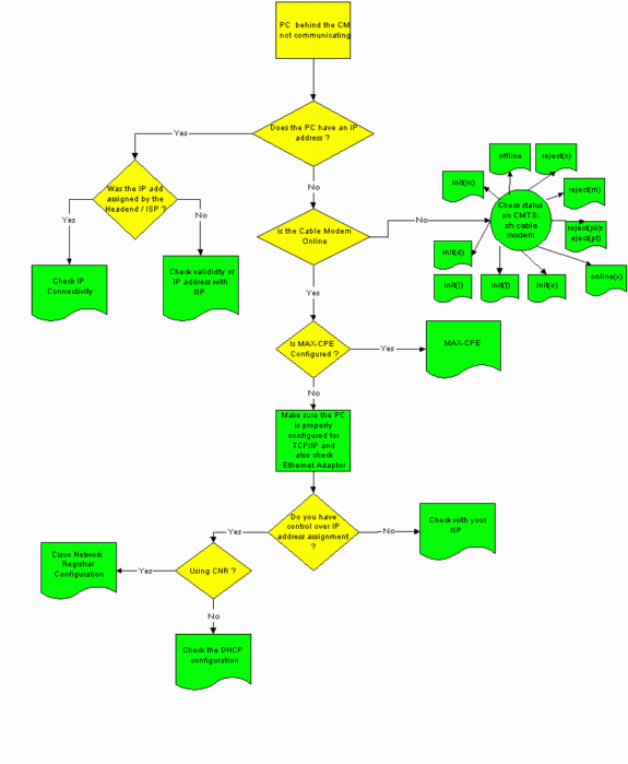
Check Status on CMTS
You must first determine if the CPE has obtained an IP address (see the Check CPE Configuration section of this document). If an IP address has not been assigned to the CPE, confirm that the cable modem is online. The CPE can not obtain an IP address if the cable modem has not come onlinecome online.
To check the status on CMTS, issue the show cable modem command from the CMTS. Sample output from this command is shown below.
Sniper# show cable modem
Interface   Prim Online     Timing Rec    QoS CPE IP address      MAC address
            Sid  State      Offset Power
Cable2/0/U0 1    offline    2291    0.00  2   0   10.50.50.4      0050.7366.2223
Cable2/0/U0 2    online     2814    0.25  5   0   10.50.50.5      0001.9659.4449
Cable2/0/U0 3    online     2813    0.50  5   0   10.50.50.2      0001.9659.4477
The Online State column above shows the status of the cable modem. For the CPE to successfully obtain an IP address and establish connectivity, the cable modem must be in one of the following states:
-
Online
-
Online (pt)
Any state other than the two above indicates that the cable modem has not registered with the CMTS and, therefore, the CPE can not obtain an IP address.
For comprehensive information about troubleshooting the possible cable modem states, refer to Troubleshooting uBR Cable Modems Not Coming Online.
Check CPE Configuration
A PC running Windows 95, 98, NT, or 2000 needs to have a TCP/IP stack that is properly installed and configured in order to obtain an IP address.
Sample screen shots in this document show a client running Windows 2000. Other Windows operating systems have similar configurations, though the appearance of the dialog boxes and the command issued to access the IP Configuration window may differ.
Note: This section assumes that the client PC has an Ethernet adapter that is properly installed and configured. If not, refer to your product documentation or ask the supplier of your adapter for assistance.
To check the IP address assigned to the PC, use the following procedure:
-
Click on Start > Run.
-
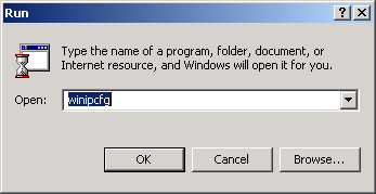
In the Run window, type winipcfg.
-
Click OK
The IP Configuration window appears.
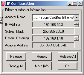
Note: If there is more than one Ethernet adapter installed in the client PC, select the adapter connected to the cable modem using the Adapter Name drop-down arrow.
From the CMTS side, you can check which CPE sits behind which cable modem and check the IP address assigned to the CPE by issuing the show interfaces cable x/y modem z command. The arguments of this command are determined as follows:
-
x is the line card number.
-
y is the downstream port number.
-
z is the Service Identifier (SID) of the cable modem.
You may set z to 0 to view details about all cable modems and CPE on a particular downstream interface. See the show interface cable command output at the end of the Sample Configuration section of this document.
If the IP address is 0.0.0.0, then the CPE has failed to obtain an IP address. Before you proceed to the next step, click the Renew button to try to obtain an IP address. If the CPE can not obtain an IP address, you will receive an IpReneweAddress failed with error 2 message in Windows 2000.
Note: In Windows 98, the CPE is sometimes assigned an IP address beginning 169.254.n.n. This type of address is a “dummy” IP address that Windows assigns, and it indicates that a working IP address has not been obtained.
-
-
Check that the CPE has a TCP/IP stack that is properly installed and configured, as shown below.
-
Choose Start > Settings > Network and Dial-up Connections > Local Area Connection.
-
In the Local Area Connection screen, click Properties.
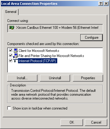
The Local Area Connection Properties window appears.
-
Ensure that Internet Protocol (TCP/IP) is listed and selected.
If not, you must install it.
-
-
After ensuring that a TCP/IP stack is installed, check that it is properly configured, as shown below.
-
In the Local Area Connection Properties window, choose Internet Protocol (TCP/IP).
-
Click Properties.
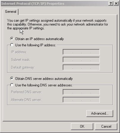
The Internet Protocol (TCP/IP) Properties window appears.
-
Ensure that the Obtain an IP address automatically and Obtain DNS server address automatically radio buttons are selected.
Note: To check TCP/IP configuration on other types of clients—for example, CPE running UNIX operating systems—consult your product documentation.
-
MAX-CPE
In bridging mode, the default MAX-CPE entry in the DOCSIS configuration file is 1. Thus, only one CPE may be connected behind the cable modem. A new configuration command allows CMTS to specify a maximum number of permitted hosts per modem (overriding the MAX-CPE value in the DOCSIS configuration file). This command is cable modem max-cpe [n | unlimited] . The valid range for n is 1 to 254.
For more information on this command and its relationship to the MAX-CPE in the DOCSIS configuration file, refer to Using the max-cpe Command in the DOCSIS and CMTS.
If the MAX-CPE parameter in the DOCSIS configuration file is 0 and the no cable modem max-cpe command is configured on the CMTS (by default) then no CPE can obtain IP addresses.
Cisco Network Registrar
Check the following in Cisco Network Registrar (CNR):
-
Properly configured Policies for each CPE.
-
Scopes to associate with those CPE Policies.
-
Sufficient IP address space to accommodate all clients, in case all clients come online at the same time.
-
The DHCP server is not overloaded.
-
There is a route back from the DHCP server to the network address of the CPE.
For more information about configuring CNR, refer to Cisco Network Registrar Configuration.
Not Using CNR
If you are using a non-CNR DHCP server, ensure that it is set up correctly according to the product’s documentation. It should be configured in a way that is similar to the Cisco Network Registrar section above.
Check With Your ISP
If you do not control IP address assignment—apart from ensuring that the cable modem is online—you must check with your ISP to troubleshoot CPE connection problems. Your ISP has control over the IP address assignment, and you might have to provide them with the MAC addresses used by your CPE.
Note: If you have access to the CMTS then you can view and troubleshoot whether the modem is online or not. Refer to Troubleshooting uBR Cable Modems Not Coming Online. Otherwise check the LED status on your Cisco uBR900 Series Cable Access Routers.
IP Address Not Assigned by ISP
IP addresses must be assigned by the ISP through a DHCP server. If your IP address is assigned using a different method—for example, static configuration—you must check the validity of the assigned IP address with your ISP. Failure to do so might cause network disruptions to other users and failures to establish connectivity.
Check IP Connectivity
If your CPE is assigned a valid IP address by your ISP but you are still unable to establish connectivity, there is a way to check IP connectivity. First, ping the IP address of the PC. Then, ping each hop in the network one at a time, to see how far through the network you can reach. If pings to the rest of the systems on the network are timing out, you must contact your ISP support personnel for assistance.
Sample Configuration
This configuration is based on Cisco IOS® Software Release 12.1(5)T.
write terminal
Sniper# write terminal

Building configuration...


Current configuration : 2472 bytes
!
version 12.1
no service single-slot-reload-enable
service timestamps debug uptime
service timestamps log uptime
no service password-encryption
service udp-small-servers max-servers no-limit
!
hostname Sniper
!
boot system flash slot0:ubr7200-ik1st-mz.121-5.T.bin
logging rate-limit console 10 except errors
enable password cisco
!
no cable qos permission create
no cable qos permission update
cable qos permission modems
cable time-server
ip subnet-zero
no ip finger
no ip domain-lookup
!
!
interface FastEthernet0/0
 no ip address
 shutdown
 half-duplex
!
interface Ethernet1/0
 ip address 172.17.110.148 255.255.255.224
 half-duplex
!
interface Ethernet1/1
 no ip address
 shutdown
 half-duplex
!
interface Cable2/0
 ip address 192.168.50.1 255.255.255.0 secondary
 ip address 10.50.50.1 255.255.255.0
 no keepalive
 cable downstream annex B
 cable downstream modulation 64qam
 cable downstream interleave-depth 32
 cable downstream frequency 555000000
 cable upstream 0 frequency 30000000
 cable upstream 0 power-level 0
 no cable upstream 0 shutdown
 cable upstream 1 shutdown
 cable upstream 2 shutdown
 cable upstream 3 shutdown
 cable upstream 4 shutdown
 cable upstream 5 shutdown
 cable dhcp-giaddr policy
 cable helper-address 172.17.110.137
!
interface Cable3/0
 no ip address
 no keepalive
 shutdown
 cable downstream annex B
 cable downstream modulation 64qam
 cable downstream interleave-depth 32
 cable upstream 0 shutdown
 cable upstream 1 shutdown
 cable upstream 2 shutdown
 cable upstream 3 shutdown
 cable upstream 4 shutdown
 cable upstream 5 shutdown
!
ip classless
ip route 0.0.0.0 0.0.0.0 172.17.110.129
no ip http server
!
line con 0
 exec-timeout 0 0
 transport input none
line aux 0
line vty 0
 exec-timeout 0 0
 password cisco
 no login
line vty 1 4
 exec-timeout 0 0
 no login
!
end

Sniper#
show interfaces cable
Sniper# show interfaces cable 2/0 modem 0
SID   Priv bits  Type      State     IP address    method    MAC address
7     00         modem     up        10.50.50.5    dhcp      0001.9659.4449
8     00         host      unknown   192.168.50.3  dhcp      0010.a4e6.d04d
8     00         modem     up        10.50.50.2    dhcp      0001.9659.4477
9     00         modem     up        10.50.50.4    dhcp      0050.7366.2223

Sniper#
Related Information
Revision History
| Revision | Publish Date | Comments |
|---|---|---|
1.0 |
04-Oct-2005 |
Initial Release |
Contact Cisco
- Open a Support Case

- (Requires a Cisco Service Contract)


 Feedback