Cable Fiber Node Best Practices for the uBR10k
Available Languages
Contents
Introduction
The cable fiber-node <n> command allows the MSO or service provider to configure the cable modem termination system (CMTS) to be more intelligent by making Cisco IOS aware of how the cable plant is wired. This allows the CMTS to implement features more effectively. This command is vital when you deploy DOCSIS 3.0 and upstream spectrum management now, and will be just as important in the future. With the addition of features in the future, or modifications of legacy features for improvements, the correct fiber node configuration is essential.
Prerequisites
Requirements
The fiber node configuration is available in Cisco IOS® Software Release 12.3(21)BC and later.
Components Used
The information in this document is based on the uBR10k.
Conventions
Refer to Cisco Technical Tips Conventions for more information on document conventions.
Problem Statement
When you initially deploy the fiber node configuration, you can shortcut the configuration of the fiber nodes based on the current use of features within the CMTS. This causes more difficulty when you deploy features that require an accurate description of the cable plant topology. The solution is to avoid the use of shortcuts and configure the cable fiber nodes to accurately describe to the CMTS, the actual cable plant topology.
Issues/Limitations
Though the intention of the cable fiber node configuration is meant to make the CMTS “plant aware”, there is a limitation. The cable fiber node configuration does not allow downstream interfaces to be combined into the same fiber node unless they share the same bundle interface. The examples included in this document assume that all interfaces that share the same fiber node use the same bundle interface.
Guidelines
DOCSIS 3.0 - There can be several reasons why DOCSIS 3.0 is not deployed on a CMTS with the capability, or perhaps not deployed on every fiber node. The fiber node feature can and should be configured regardless. There are three scenarios to examine when you deal with the fiber node configuration. Some fiber nodes have no wideband deployed, some fiber nodes do. The third scenario is to have a combination of the first two scenarios. Two downstream channels, one for legacy narrowband cable modems, and the other for wideband cable modems.
-
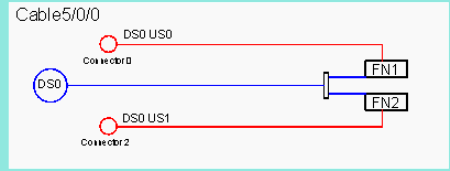
Deploy without WB—Figure 1 shows a 1x2 MAC domain with each upstream configured for one fiber node. In this scenario, there is no wideband.
Figure 1cable fiber-node 1 downstream Cable5/0/0 upstream Cable 5/0 connector 0 cable fiber-node 2 downstream Cable5/0/0 upstream Cable 5/0 connector 2

-
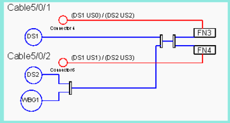
Combine NB w/ NB+WBGs—Figure 2 shows two 1x2 MAC domains. The first, C5/0/1, is for legacy DOCSIS only, while C5/0/2 is used for DOCSIS 3.0 and combined with a WideBand group. In order to isolate C5/0/1 as legacy only, it is necessary to use the downstream frequency option in the DOCSIS configuration file to direct the wideband modems to C5/0/2 and the narrow band legacy modems to C5/0/1. The fiber node configuration on the cmts illustrates the point of configuring exactly how the fiber nodes are wired without concern for where wideband is actually deployed. In this case, the upstream connectors use frequency stacking in order to configure an upstream from each MAC domain.
Figure 2cable fiber-node 3 downstream Cable5/0/1 downstream Cable5/0/2 downstream Modular-Cable 1/0/0 rf-channel 0 1 upstream Cable 5/0 connector 4 cable fiber-node 4 downstream Cable5/0/1 downstream Cable5/0/2 downstream Modular-Cable 1/0/0 rf-channel 0 1 upstream Cable 5/0 connector 6

-
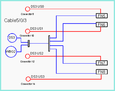
Full WB deployment—Figure 3 shows a full deployment of wideband on a single 1x4 MAC domain feeding 4 fiber nodes. The same holds true from the previous examples with the use of frequency stacking and spectrum management.
Figure 3cable fiber-node 5 downstream Cable5/0/3 downstream Modular-Cable 1/0/0 rf-channel 2 3 upstream Cable 5/0 connector 8 cable fiber-node 6 downstream Cable5/0/3 downstream Modular-Cable 1/0/0 rf-channel 2 3 upstream Cable 5/0 connector 10 cable fiber-node 7 downstream Cable5/0/3 downstream Modular-Cable 1/0/0 rf-channel 2 3 upstream Cable 5/0 connector 12 cable fiber-node 8 downstream Cable5/0/3 downstream Modular-Cable 1/0/0 rf-channel 2 3 upstream Cable 5/0 connector 14

Upstream Spectrum Management
In each of the scenarios mentioned in the previous section, the upstream connectors are added to the fiber node regardless of the upstream spectrum management.
-
Figure 1 shows that each node has only 1 upstream and there is no real need to add the upstream to the fiber node in order for it to function properly. However, because this is only a 1x2 MAC domain, there is the option of adding upstream bandwidth in the future. This can be implemented by use of frequency stacking an additional upstream on connector 0 and connector 2 without the need for additional wiring or combining. If shared spectrum management is used, it is absolutely necessary to add the upstream connector to the fiber node when this change is made. If you use the recommendation in the example, the upstream connector has already been added when you create the fiber node and there is no need to make additional configuration changes.
-
Figure 2 and Figure 3 show examples of shared upstream connectors. Even if the upstreams do not use shared spectrum management, it is possible that it might be necessary to add it in the future. If the upstream connectors were not in the fiber node configuration, then in both of these scenarios, all the fiber node configurations might be summed up in a single fiber node and would actually function properly. However, because the upstream connectors are already added to the fiber node configuration, a change in the spectrum management does not require a major reconfiguration of the fiber nodes.
Conclusion
The three possible scenarios discussed in this document show how to properly configure a cable fiber node on the CMTS regardless of needing the functionality. Because the cable fiber node interacts with other features, upstream and downstream, it is vital to use these recommendations in order to more efficiently manage the CMTS configuration. Cisco has added the cable fiber node functionality in order to make the CMTS more “plant aware” so that certain features can function more intelligently. This provides a smoother and more manageable operational network.
Related Information
- Virtual Interfaces and Frequency Stacking Configuration on MC5x20S and MC28U Linecards
- Cisco CMTS Feature Guide - Cable Interface Bundling and Virtual Interface Bundling for the Cisco CMTS
- Cisco MC16S Spectrum Management Card
- Cisco uBR10012 - Cisco IOS Release 12.3 BC
- Technical Support & Documentation - Cisco Systems
Revision History
| Revision | Publish Date | Comments |
|---|---|---|
1.0 |
28-Feb-2007 |
Initial Release |
Contact Cisco
- Open a Support Case

- (Requires a Cisco Service Contract)


 Feedback