Upstream Scheduler Mode Configuration for the Cisco uBR CMTS
Available Languages
Contents
Introduction
This document discusses the configuration of upstream scheduler mode for the Cisco Universal Broadband Router (uBR) series of Cable Modem Termination Systems (CMTS).
This document focusses on personnel who work with the design and maintenance of high speed data-over-cable networks that make use of latency and jitter-sensitive upstream services, for example, voice or video over IP.
Prerequisites
Requirements
Cisco recommends that you have knowledge of these topics:
-
Data over Cable Service Interface Specification (DOCSIS) systems
-
The Cisco uBR series of CMTS
Components Used
The information in this document is based on these software and hardware versions:
-
Cisco uBR CMTS
-
Cisco IOS® Software Release trains 12.3(13a)BC and 12.3(17a)BC
Note: For information on changes in later releases of Cisco IOS Software, refer to the appropriate release notes available at the Cisco.com web site.
Conventions
Refer to Cisco Technical Tips Conventions for more information on document conventions.
Background Information
In a Data-over-Cable Service Interface Specifications (DOCSIS) network, the CMTS controls the timing and rate of all upstream transmissions that cable modems make. Many different kinds of services with different latency, jitter and throughput requirements run simultaneously on a modern DOCSIS network upstream. Therefore, you must understand how the CMTS decides when a cable modem can make upstream transmissions on behalf of these different types of services.
This white paper includes:
-
An overview of upstream scheduling modes in DOCSIS, including best effort, Unsolicited Grant Service (UGS) and real time polling service (RTPS)
-
The operation and configuration of the DOCSIS-compliant scheduler for the Cisco uBR CMTS
-
The operation and configuration of the new low latency queueing scheduler for the Cisco uBR CMTS
Upstream Scheduling in DOCSIS
A DOCSIS-compliant CMTS can provide different upstream scheduling modes for different packet streams or applications through the concept of a service flow. A service flow represents either an upstream or a downstream flow of data, which a service flow ID (SFID) uniquely identifies. Each service flow can have its own quality of service (QoS) parameters, for example, maximum throughput, minimum guaranteed throughput and priority. In the case of upstream service flows, you can also specify a scheduling mode.
You can have more than one upstream service flow for every cable modem to accommodate different types of applications. For example, web and email can use one service flow, voice over IP (VoIP) can use another, and Internet gaming can use yet another service flow. In order to be able to provide an appropriate type of service for each of these applications, the characteristics of these service flows must be different.
The cable modem and CMTS are able to direct the correct types of traffic into the appropriate service flows with the use of classifiers. Classifiers are special filters, like access-lists, that match packet properties such as UDP and TCP port numbers to determine the appropriate service flow for packets to travel through.
In Figure 1 a cable modem has three upstream service flows. The first service flow is reserved for voice traffic. This service flow has a low maximum throughput but is also configured to provide a guarantee of low latency. The next service flow is for general web and email traffic. This service flow has a high throughput. The final service flow is reserved for peer to peer (P2P) traffic. This service flow has a more restrictive maximum throughput to throttle back the speed of this application.
Figure 1 – A Cable Modem with Three Upstream Service Flows 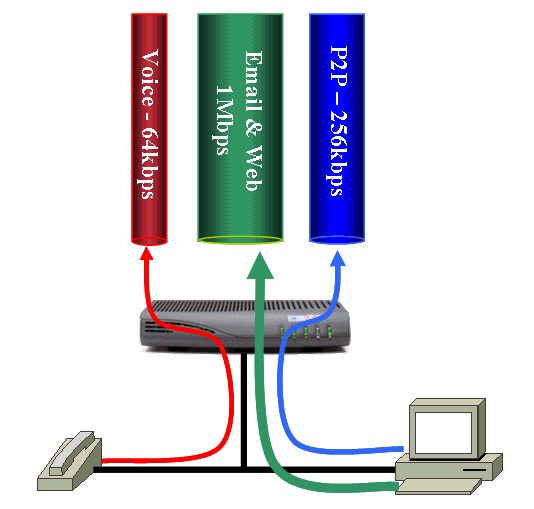
Service flows are established and activated when a cable modem first comes online. Provision the details of the service flows in the DOCSIS configuration file that you use to configure the cable modem. Provision at least one service flow for the upstream traffic, and one other service flow for the downstream traffic in a DOCSIS configuration file. The first upstream and downstream service flows that you specify in the DOCSIS configuration file are called the primary service flows.
Service flows can also be dynamically created and activated after a cable modem comes online. This scenario generally applies to a service flow, which corresponds to data that belongs to a VoIP telephone call. Such a service flow is created and activated when a telephone conversation begins. The service flow is then deactivated and deleted when the call ends. If the service flow exists only when necessary, you can save upstream bandwidth resources and system CPU load and memory.
Cable modems cannot make upstream transmissions anytime. Instead, modems must wait for instructions from the CMTS before they can send data, because only one cable modem can transmit data on an upstream channel at a time. Otherwise, transmissions can overrun and corrupt each other. The instructions for when a cable modem can make a transmission come from the CMTS in the form of a bandwidth allocation MAP message. The Cisco CMTS transmits a MAP message every 2 milliseconds to tell the cable modems when they can make a transmission of any kind. Each MAP message contains information that instructs modems exactly when to make a transmission, how long the transmission can last, and what type of data they can transmit. Thus, cable modem data transmissions do not collide with each other, and avoid data corruption. This section discusses some of the ways in which a CMTS can determine when to grant a cable modem permission to make a transmission in the upstream.
Best Effort
Best effort scheduling is suitable for classical internet applications with no strict requirement on latency or jitter. Examples of these types of applications include email, web browsing or peer-to-peer file transfer. Best effort scheduling is not suitable for applications that require guaranteed latency or jitter, for example, voice or video over IP. This is because in congested conditions no such guarantee can be made in best effort mode. DOCSIS 1.0 systems allow only this type of scheduling.
Best effort service flows are usually provisioned in the DOCSIS configuration file associated with a cable modem. Therefore, best effort service flows are generally active as soon as the cable modem comes online. The primary upstream service flow, that is the first upstream service flow to be provisioned in the DOCSIS configuration file, must be a best effort style service flow.
Here are the most commonly used parameters that define a best effort service flow in DOCSIS 1.1/2.0 mode:
-
Maximum Sustained Traffic Rate (R)
Maximum Sustained Traffic Rate is the maximum rate at which traffic can operate over this service flow. This value is expressed in in bits per second.
-
Maximum Traffic Burst (B)
Maximum Traffic Burst refers to the burst size in bytes that applies to the token bucket rate limiter that enforces upstream throughput limits. If no value is specified, the default value of 3044 applies, which is the size of two full ethernet frames. For large maximum sustained traffic rates, set this value to be at least the maximum sustained traffic Rate divided by 64.
-
Traffic Priority
This parameter refers to the priority of traffic in a service flow ranging from 0 (the lowest) to 7 (the highest). In the upstream all pending traffic for high priority service flows are scheduled for transmission before traffic for low priority service flows.
-
Minimum Reserved Rate
This parameter indicates a minimum guaranteed throughput in bits per second for the service flow, similar to a committed information rate (CIR). The combined minimum reserved rates for all service flows on a channel must not exceed the available bandwidth on that channel. Otherwise it is impossible to guarantee the promised minimum reserved rates.
-
Maximum Concatenated Burst
Maximum Concatenated Burst is the size in bytes of the largest transmission of concatenated frames that a modem can make on behalf of the service flow. As this parameter implies, a modem can transmit multiple frames in one burst of transmission. If this value is not specified, DOCSIS 1.0 cable modems and older DOCSIS 1.1 modems assume that there is no explicit limit set on the concatenated burst size. Modems compliant with more recent revisions of the DOCSIS 1.1 or later specifications use a value of 1522 bytes.
When a cable modem has data to transmit on behalf of an upstream best effort service flow, the modem cannot simply forward the data onto the DOCSIS network with no delay. The modem must go through a process where the modem requests exclusive upstream transmission time from the CMTS. This request process ensures that the data does not collide with the transmissions of another cable modem connected to the same upstream channel.
Sometimes the CMTS schedules certain periods in which the CMTS allows cable modems to transmit special messages called bandwidth requests. The bandwidth request is a very small frame that contains details of the amount of data the modem wants to transmit, plus a service identifier (SID) that corresponds to the upstream service flow that needs to transmit the data. The CMTS maintains an internal table matching SID numbers to upstream service flows.
The CMTS schedules bandwidth request opportunities when no other events are scheduled in the upstream. In other words, the scheduler provides bandwidth request opportunities when the upstream scheduler has not planned for a best effort grant, or UGS grant or some other type of grant to be placed at a particular point. Therefore, when an upstream channel is heavily utilized, fewer opportunities exist for cable modems to transmit bandwidth requests.
The CMTS always ensures that a small number of bandwidth request opportunities are regularly scheduled, no matter how congested the upstream channel becomes. Multiple cable modems can transmit bandwidth requests at the same time, and corrupt each other’s transmissions. In order to reduce the potential for collisions that can corrupt bandwidth requests, a “backoff and retry” algorithm is in place. The subsequent sections of this document discuss this algorithm.
When the CMTS receives a bandwidth request from a cable modem, the CMTS performs these actions:
-
The CMTS uses the SID number received in the bandwidth request to examine the service flow with which the bandwidth request is associated.
-
The CMTS then uses the token bucket algorithm. This algorithm helps the CMTS to check whether the service flow will exceed the prescribed maximum sustained rate if the CMTS grants the requested bandwidth. Here is the computation of the token bucket algorithm:
Max(T) = T * (R / 8) + B
where:
-
Max(T) indicates The maximum number of bytes that can be transmitted on the service flow over time T.
-
T represents time in seconds.
-
R indicates the maximum sustained traffic rate for the service flow in bits per second
-
B is the maximum traffic burst for the service flow in bytes.
-
-
When the CMTS ascertains that the bandwidth request is within throughput limits, the CMTS queues the details of the bandwidth request to the upstream scheduler. The upstream scheduler decides when to grant the bandwidth request.
The Cisco uBR CMTS implements two upstream scheduler algorithms, called the DOCSIS compliant scheduler and the low latency queueing scheduler. See The DOCSIS Compliant Scheduler section and Low Latency Queueing Scheduler section of this document for more information.
-
The CMTS then includes these details in the next periodic bandwidth allocation MAP message:
-
When the cable modem is able to transmit.
-
For how long the cable modem is able to transmit.
-
Bandwidth Request Backoff and Retry Algorithm
The bandwidth request mechanism employs a simple “backoff and retry” algorithm to reduce, but not totally eliminate, the potential for collisions between multiple cable modems that transmit bandwidth requests simultaneously.
A cable modem that decides to transmit a bandwidth request must first wait for a random number of bandwidth request opportunities to pass before the modem makes the transmission. This wait time helps reduce the possibility of collisions that occur due to simultaneous transmissions of bandwidth requests.
Two parameters called the data backoff start and the data backoff end determine the random waiting period. The cable modems learn these parameters as a part of the contents of the periodic upstream channel descriptor (UCD) message. The CMTS transmits the UCD message on behalf of each active upstream channel every two seconds.
These backoff parameters are expressed as “power of two” values. Modems use these parameters as powers of two to calculate how long to wait before they transmit bandwidth requests. Both values have a range of 0 to 15 and data backoff end must be greater than or equal to data backoff start.
The first time a cable modem wants to transmit a particular bandwidth request, the cable modem must first pick a random number between 0 and 2 to the power of data backoff start minus 1. For example, if data backoff start is set to 3, the modem must pick a random number between 0 and (23 – 1) = (8 – 1) = 7.
The cable modem must then wait for the selected random number of bandwidth request transmission opportunities to pass before the modem transmits a bandwidth request. Thus, while a modem cannot transmit a bandwidth request at the next available opportunity due to this forced delay, the possibility of a collision with another modem’s transmission reduces.
Naturally the higher the data backoff start value, lower is the possibility of collisions between bandwidth request. Larger data backoff start values also mean that modems potentially have to wait longer to transmit bandwidth requests, and so upstream latency increases.
The CMTS includes an acknowledgement in the next transmitted bandwidth allocation MAP message. This acknowledgment informs the cable modem that the bandwidth request was successfully received. This acknowledgement can:
-
either indicate exactly when the modem can make the transmission
OR
-
only indicate that the bandwidth request was received and that a time for transmission will be decided in a future MAP message.
If the CMTS does not include an acknowledgement of the bandwidth request in the next MAP message, the modem can conclude that the bandwidth request was not received. This situation can occur due to a collision, or upstream noise, or because the service flow exceeds the prescribed maximum throughput rate if the request is granted.
In either case, the next step for the cable modem is to backoff, and try to transmit the bandwidth request again. The modem increases the range over which a random value is chosen. To do so, the modem adds one to the data backoff start value. For example, if the data backoff start value is 3, and the CMTS fails to receive one bandwidth request transmission, the modem waits a random value between 0 and 15 bandwidth request opportunities before retransmission. Here is the calculation: 23+1 – 1 = 24 – 1 = 16 – 1 = 15
The larger range of values reduces the chance of another collision. If the modem loses further bandwidth requests, the modem continues to increment the value used as the power of two for each retransmission until the value is equal to data backoff end. The power of two must not grow to be larger than the data backoff end value.
The modem retransmits a bandwidth request up to 16 times, after which the modem discards the bandwidth request. This situation occurs only in extremely congested conditions.
You can configure the data backoff start and data backoff end values per cable upstream on a Cisco uBR CMTS with this cable interface command:
cable upstream upstream-port-id data-backoff data-backoff-start data-backoff-end
Cisco recommends that you retain the default values for data-backoff-start and data-backoff-end parameters, which are 3 and 5. The contention-based nature of the best effort scheduling system means that for best effort service flows, it is impossible to provide a deterministic or guaranteed level of upstream latency or jitter. In addition, congested conditions can make it impossible to guarantee a particular level of throughput for a best effort service flow. However, you can use service flow properties like priority and minimum reserved rate. With these properties, service flow can achieve the desired level of throughput in congested conditions.
Example of the Backoff and Retry Algorithm
This example comprises four cable modems named A, B, C and D, connected to the same upstream channel. At the same instant called t0, modems A, B and C decide to transmit some data in the upstream.
Here, data backoff start is set to 2 and data backoff end is set to 4. The range of intervals from which the modems pick an interval before they first attempt to transmit a bandwidth request is between 0 and 3. Here is the calculation:
(22 – 1) = (4 – 1) = 3 intervals.
Here are the number of bandwidth request opportunities that the three modems pick to wait from time t0.
-
Modem A: 3
-
Modem B: 2
-
Modem C: 3
Notice that modem A and modem C pick the same number of opportunities to wait.
Modem B waits for two bandwidth request opportunities that appear after t0. Modem B then transmits the bandwidth request, which the CMTS receives. Both modem A and modem C wait for 3 bandwidth request opportunities to pass after t0. Modems A and C then transmit bandwidth requests at the same time. These two bandwidth requests collide and become corrupt. As a result, neither request successfully reaches the CMTS. Figure 2 shows this sequence of events.
Figure 2 – Bandwidth Request Example Part 1 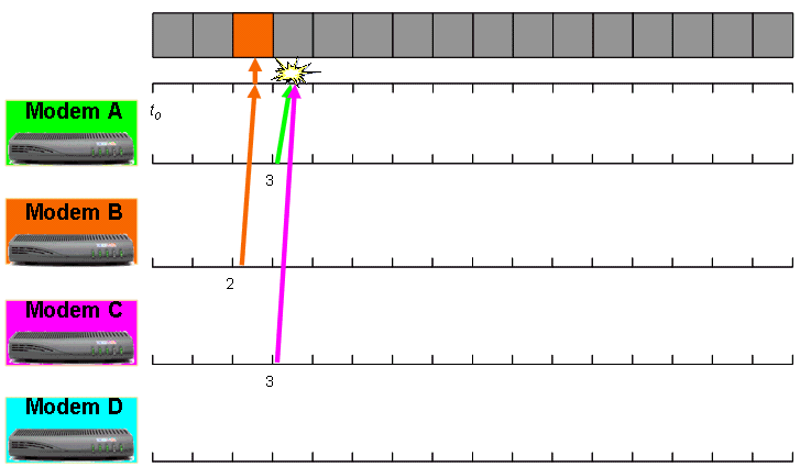
The gray bar at the top of the diagram represents a series of bandwidth request opportunities available to cable modems after time t0. The colored arrows represent bandwidth requests that the cable modems transmit. The colored box within the gray bar represents a bandwidth request that reaches the CMTS successfully.
The next MAP message broadcast from the CMTS contains a grant for modem B but no instructions for modems A and C. This indicates to modems A and C that they need to retransmit their bandwidth requests.
On the second try, modem A and modem C need to increment the power of two to use when they calculate the range of intervals from which to pick. Now, modem A and modem C pick a random number of intervals between 0 and 7. Here is the computation:
(22+1 -1) = (23 – 1) = (8 – 1) = 7 intervals.
Assume that the time when modem A and modem C realize the need to retransmit is t1. Also assume that another modem called modem D decides to transmit some upstream data at the same instant, t1. Modem D is about to make a bandwidth request transmission for the first time. Therefore, modem D uses the original value for data backoff start and data backoff end, namely between 0 and 3 [(22 – 1) = (4 – 1) = 3 intervals].
The three modems pick these random number of bandwidth request opportunities to wait from time t1.
-
Modem A: 5
-
Modem C: 2
-
Modem D: 2
Both modems C and D wait for two bandwidth request opportunities that appear after time t1. Modems C and D then transmit bandwidth requests at the same time. These bandwidth requests collide and therefore do not reach the CMTS. Modem A allows five bandwidth request opportunities to pass. Then, modem A transmits the bandwidth request, which the CMTS receives. Figure 3 shows the collision between the transmission of modems C and D, and the successful receipt of the transmission of modem A. The start time reference for this figure is t1.
Figure 3 – Bandwidth Request Example Part 2 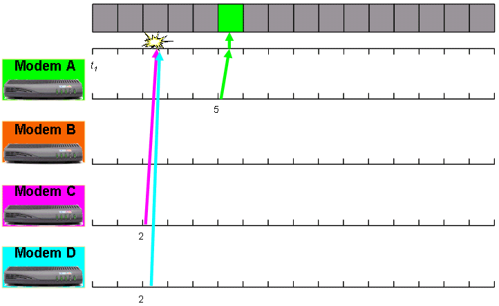
The next MAP message broadcast from the CMTS contains a grant for modem A but no instructions for modems C and D. Modems C and D realize the need to retransmit the bandwidth requests. Modem D is now about to transmit the bandwidth request for the second time. Therefore, modem D uses data backoff start + 1 as the power of two to use in the calculation of the range of intervals to wait. Modem D chooses an interval between 0 and 7. Here is the calculation:
(22+1 – 1) = (23 – 1) = (8 – 1) = 7 intervals.
Modem C is about to transmit the bandwidth request for the third time. Therefore, modem C uses data backoff start + 2 as the power of two to in the calculation of the range of intervals to wait. Modem C chooses an interval between 0 and 15. Here is the calculation:
(22+2 – 1) = (24 – 1) = (16 – 1) = 15 intervals.
Note that the power of two here is the same as the data backoff end value, which is four. This is the highest that the power of two value can be for a modem on this upstream channel. In the next bandwidth request transmission cycle, the two modems pick these number of bandwidth request opportunities to wait:
-
Modem C: 9
-
Modem D: 4
Modem D is able to transmit the bandwidth request because modem D waits for four bandwidth request opportunities to pass. In addition, modem C is also able to transmit the bandwidth request, because modem C now defers transmission for nine bandwidth request opportunities.
Unfortunately, when modem C makes a transmission, a large burst of ingress noise interferes with the transmission, and the CMTS fails to receive the bandwidth request (see Figure 4). As a result, once again, modem C fails to see a grant in the next MAP message that the CMTS transmits. This makes modem C attempt a fourth transmission of the bandwidth request.
Figure 4 – Bandwidth Request Example Part 3 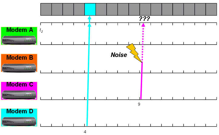
Modem C has already reached the data backoff end value of 4. Modem C cannot increase the range used to pick a random number of intervals to wait. Therefore, modem C once again uses 4 as the power of two to calculate the random range. Modem C still uses the range 0 to 15 intervals as per this calculation:
(24 – 1) = (16 – 1) = 15 intervals.
On the fourth attempt, modem C is able to make a successful bandwidth request transmission in the absence of contention or noise.
The multiple bandwidth request retransmissions of modem C in this example demonstrates what can happen on a congested upstream channel. This example also demonstrates the potential issues involved with the best effort scheduling mode and why best effort scheduling is not suitable for services that require strictly controlled levels of packet latency and jitter.
Traffic Priority
When the CMTS has multiple pending bandwidth requests from several service flows, CMTS looks at the traffic priority of each service flow to decide which ones to grant bandwidth first.
The CMTS grants transmission time to all pending requests from service flows with a higher priority before bandwidth requests from service flows with a lower priority. In congested upstream conditions, this generally leads to higher throughput for high priority service flows compared to low priority service flows.
An important fact to note is that while a high priority best effort service flow is more likely to receive bandwidth quickly, the service flow is still subject to the possibility of bandwidth request collisions. For this reason while traffic priority can enhance the throughput and latency characteristics of a service flow, traffic priority is still not an appropriate way to provide a service guarantee for applications that require one.
Minimum Reserved Rate
Best effort service flows can receive a minimum reserved rate with which to comply. The CMTS ensures that a service flow with a specified minimum reserved rate receives bandwidth in preference to all other best effort service flows, regardless of priority.
This method is an attempt to provide a kind of committed information rate (CIR) style service analogous to a frame-relay network. The CMTS has admission control mechanisms to ensure that on a particular upstream the combined minimum reserved rate of all connected service flows cannot exceed the available bandwidth of the upstream channel, or a percentage thereof. You can activate these mechanisms with this per upstream port command:
[no] cable upstream upstream-port-id admission-control max-reservation-limit
The max-reservation-limit parameter has a range of 10 to 1000 percent to indicate the level of subscription as compared to the available raw upstream channel throughput that CIR style services can consume. If you configure a max-reservation-limit of greater than 100, the upstream can oversubscribe CIR style services by the specified percentage limit.
The CMTS does not allow new minimum reserved rate service flows to be established if they would cause the upstream port to exceed the configured max-reservation-limit percentage of the available upstream channel bandwidth. Minimum reserved rate service flows are still subject to potential collisions of bandwidth requests. As such, minimum reserved rate service flows cannot provide a true guarantee of a particular throughput, especially in extremely congested conditions. In other words, the CMTS can only guarantee that a minimum reserved rate service flow is able to achieve a particular guaranteed upstream throughput if the CMTS is able to receive all the required bandwidth requests from the cable modem. This requirement can be achieved if you make the service flow a real time polling service (RTPS) service flow instead of a best effort service flow. See the Real Time Polling Service (RTPS) section for more information.
Piggyback Bandwidth Requests
When an upstream best effort service flow transmits frames at a high rate, it is possible to piggyback bandwidth requests onto upstream data frames rather than have separate transmission of the bandwidth requests. The details of the next request for bandwidth are simply added to the header of a data packet being transmitted in the upstream to the CMTS.
This means that the bandwidth request is not subject to contention and therefore has a much higher chance that the request reaches the CMTS. The concept of piggyback bandwidth requests reduces the time that an Ethernet frame takes to reach the customer premise equipment (CPE) of the end user, because the time that the frame takes in upstream transmission reduces. This is because the modem does not need to go through the backoff and retry bandwidth request transmission process, which can be subject to delays.
Piggybacking of bandwidth requests typically occurs in this scenario:
While the cable modem waits to transmit a frame, say X, in the upstream, the modem receives another frame, say Y, from a CPE to transmit in the upstream. The cable modem cannot add the bytes from the new frame Y on to the transmission, because that involves the usage of more upstream time than the modem is granted. Instead, the modem fills in a field in the DOCSIS header of frame X to indicate the amount of transmission time required for frame Y.
The CMTS receives frame X and also the details of a bandwidth request on behalf of Y. On the basis of availability, the CMTS grants the modem further transmission time on behalf of Y.
In very conservative terms, as short as 5 milliseconds elapse between the transmission of a bandwidth request and receipt of bandwidth allocation as well as MAP acknowledgment that assigns time for data transmission. This means that for piggybacking to occur, the cable modem needs to receive frames from the CPE within less than 5ms of each other.
This is noteworthy because, a typical VoIP codec like G.711 generally uses an inter-frame period of 10 or 20ms. A typical VoIP stream that operates over a best effort service flow cannot take advantage of piggybacking.
Concatenation
When an upstream best effort service flow transmits frames at a high rate, the cable modem can join a few of the frames together and ask for permission to transmit the frames all at once. This is called concatenation. The cable modem needs to transmit only one bandwidth request on behalf of all the frames in a group of concatenated frames, which improves efficiency.
Concatenation tends to occur in circumstances similar to piggybacking except that concatenation requires multiple frames to be queued inside the cable modem when the modem decides to transmit a bandwidth request. This implies that concatenation tends to occur at higher average frame rates than piggybacking. Also, both mechanisms commonly work together to improve the efficiency of best effort traffic.
The Maximum Concatenated Burst field that you can configure for a service flow limits the maximum size of a concatenated frame that a service flow can transmit. You can also use the cable default-phy-burst command to limit the size of a concatenated frame and the maximum burst size in the upstream channel modulation profile.
Concatenation is enabled by default on the upstream ports of the Cisco uBR series of CMTS. However, you can control concatenation on a per-upstream-port basis with the [no] cable upstream upstream-port-id concatenation [docsis10] cable interface command.
If you configure the docsis10 parameter, the command only applies to cable modems that operate in DOCSIS 1.0 mode.
If you make changes to this command, cable modems must re-register on the CMTS in order for the changes to take effect. The modems on the affected upstream must be reset. A cable modem learns whether concatenation is permitted at the point where the modem performs registration as part of the process of coming online.
Fragmentation
Large frames take a long time to transmit in the upstream. This transmission time is known as the serialization delay. Especially large upstream frames can take so long to transmit that they can harmfully delay packets that belong to time sensitive services, for example, VoIP. This is especially true for large concatenated frames. For this reason, fragmentation was introduced in DOCSIS 1.1 so that large frames can be split into smaller frames for transmission in separate bursts that each take less time to transmit.
Fragmentation allows small, time sensitive frames to be interleaved between the fragments of large frames rather than having to wait for the transmission of the entire large frame. Transmission of a frame as multiple fragments is slightly less efficient than the transmission of a frame in one burst due to the extra set of DOCSIS headers that need to accompany each fragment. However, the flexibility that fragmentation adds to the upstream channel justifies the extra overhead.
Cable modems that operate in DOCSIS 1.0 mode cannot perform fragmentation.
Fragmentation is enabled by default on the upstream ports of the Cisco uBR series of CMTS. However, you can enable or disable fragmentation on a per-upstream-port basis with the [no] cable upstream upstream-port-id fragmentation cable interface command.
You do not need to reset cable modems for the command to take effect. Cisco recommends that you always have fragmentation enabled. Fragmentation normally occurs when the CMTS believes that a large data frame can interfere with the transmission of small time sensitive frames or certain periodic DOCSIS management events.
You can force DOCSIS 1.1/2.0 cable modems to fragment all large frames with the [no] cable upstream upstream-port-id fragment-force [threshold number-of-fragments] cable interface command.
By default, this feature is disabled. If you do not specify values for threshold and number-of-fragments in the configuration, the threshold is set to 2000 bytes and the number of fragments is set to 3. The fragment-force command compares the number of bytes that a service flow requests for transmission with the specified threshold parameter. If the request size is greater than the threshold, the CMTS grants the bandwidth to the service-flow in “number-of-fragments” equally sized parts.
For example, assume that for a particular upstream fragment-force is enabled with a value of 2000 bytes for threshold and 3 for number-of-fragments. Then assume that a request to transmit a 3000 byte burst arrives. As 3000 bytes is greater than the threshold of 2000 bytes, the grant must be fragmented. As the number-of-fragments is set to 3, the transmission time is three equally sized grants of 1000 bytes each.
Take care to ensure that the sizes of individual fragments do not exceed the capability of the cable line card type in use. For MC5x20S line cards, the largest individual fragment must not exceed 2000 bytes, and for other line cards, including the MC28U, MC5x20U and MC5x20H, the largest individual fragment must not exceed 4000 bytes.
Unsolicited Grant Service (UGS)
The Unsolicited Grant Service (UGS) provides periodic grants for an upstream service flow without the need for a cable modem to transmit bandwidth requests. This type of service is suitable for applications that generate fixed size frames at regular intervals and are intolerant of packet loss. Voice over IP is the classic example.
Compare the UGS scheduling system to a time slot in a time division multiplexing (TDM) system such as a T1 or E1 circuit. UGS provides a guaranteed throughput and latency, which in turn provides continuous stream of fixed periodic intervals to transmit without the need for the client to periodically request or contend for bandwidth. This system is perfect for VoIP because voice traffic is generally transmitted as a continuous stream of fixed size periodic data.
UGS was conceived because of the lack of guarantees for latency, jitter and throughput in the best effort scheduling mode. The best effort scheduling mode does not provide the assurance that a particular frame can be transmitted at a particular time, and in a congested system there is no assurance that a particular frame can be transmitted at all.
Note that although UGS style service flows are the most appropriate type of service flow to convey VoIP bearer traffic, they are not considered to be appropriate for classical internet applications such as web, email or P2P. This is because classical internet applications do not generate data at fixed periodic intervals and can, in fact, spend significant periods of time not transmitting data at all. If a UGS service flow is used to convey classical internet traffic, the service flow can go unused for significant periods when the application briefly stops transmissions. This leads to unused UGS grants that represent a waste of upstream bandwidth resources which is not desirable.
UGS service flows are usually established dynamically when they are required rather than being provisioned in the DOCSIS configuration file. A cable modem with integrated VoIP ports can usually ask the CMTS to create an appropriate UGS service flow when the modem detects that a VoIP telephone call is in progress.
Cisco recommends that you do not configure a UGS service flow in a DOCSIS configuration file because this configuration keeps the UGS service flow active for as long as the cable modem is online whether or not any services use it. This configuration wastes upstream bandwidth because a UGS service flow constantly reserves upstream transmission time on behalf of the cable modem. It is far better to allow UGS service flow to be created and deleted dynamically so that UGS is active when required.
Here are the most commonly used parameters that define a UGS service flow:
-
Unsolicited Grant Size (G)—The size of each periodic grant in bytes.
-
Nominal Grant Interval (I)—The interval in microseconds between grants.
-
Tolerated Grant Jitter (J)—The allowed variation in microseconds from exactly periodic grants. In other words, this is the leeway the CMTS has when the CMTS tries to schedule a UGS grant on time.
When a UGS service flow is active, every (I) milliseconds, the CMTS offers a chance for the service flow to transmit at Unsolicited Grant Size (G) bytes. Although ideally the CMTS offers the grant exactly every (I) milliseconds, it may be late by up to (J) milliseconds.
Figure 5 shows a timeline that demonstrates how UGS grants can be allocated with a given grant size, grant interval and tolerated jitter.
Figure 5 – Timeline that Shows Periodic UGS Grants 
The green patterned blocks represent time where the CMTS dedicates upstream transmission time to a UGS service flow.
Real Time Polling Service (RTPS)
Real Time Polling Service (RTPS) provides periodic non-contention-based bandwidth request opportunities so that a service flow has dedicated time to transmit bandwidth requests. Only the RTPS service flow is allowed to use this unicast bandwidth request opportunity. Other cable modems cannot cause a bandwidth request collision.
RTPS is suitable for applications that generate variable length frames on a semi-periodic basis and require a guaranteed minimum throughput to work effectively. Video telephony over IP or multi player online gaming are typical examples.
RTPS is also used for VoIP signaling traffic. While VoIP signaling traffic does not need to be transmitted with an extremely low latency or jitter, VoIP does need to have a high likelihood of being able to reach the CMTS in a reasonable amount of time. If you use RTPS rather than best effort scheduling you can be assured that Voice signaling is not significantly delayed or dropped due to repeated bandwidth request collisions.
An RTPS service flow typically possesses these attributes:
-
Nominal Polling Interval—The interval in microseconds between unicast bandwidth request opportunities.
-
Tolerated Poll Jitter—The allowed variation in microseconds from exactly periodic polls. Put another way, this is the leeway the CMTS has when trying to schedule an RTPS unicast bandwidth request opportunity on time.
Figure 6 shows a timeline that demonstrates how RTPS polls are allocated with a given nominal polling interval and tolerated poll jitter.
Figure 6 – Timeline that Shows Periodic RTPS Polling 
The small green patterned blocks represent time where the CMTS offers an RTPS service flow a unicast bandwidth request opportunity.
When the CMTS receives a bandwidth request on behalf of an RTPS service flow, the CMTS processes the bandwidth request in the same way as a request from a “best effort” service flow. This means that in addition to the above parameters, such properties as maximum sustained traffic rate and traffic priority must be included in an RTPS service flow definition. An RTPS service flow commonly also contains a minimum reserved traffic rate in order to ensure that the traffic associated with the service flow is able to receive a committed bandwidth guarantee.
Unsolicited Grant Service with Activity Detection (UGS-AD)
Unsolicited grant service with activity detection (UGS-AS) assigns UGS style transmission time to a service flow only when UGS-AS actually needs to transmit packets. When the CMTS detects that the cable modem has not transmitted frames for a certain period, CMTS offers RTPS style bandwidth request opportunities instead of UGS style grants. If the CMTS subsequently detects that the service flow makes bandwidth requests, the CMTS reverts the service flow back to offering UGS style grants and stops offering RTPS style bandwidth request opportunities.
UGS-AD is typically used in a situation where VoIP traffic that used voice activity detection (VAD) was being conveyed. Voice activity detection causes the VoIP end point to stop the transmission of VoIP frames if UGS-AD detects a pause in the user's speech. Although this behavior can save bandwidth, it can cause problems with voice quality, especially if the VAD or UGS-AD activity detection mechanism activates slightly after the end party starts to resume speaking. This can lead to a popping or clicking sound as a user resumes speaking after silence. For this reason UGS-AD is not widely deployed.
Issue the cable service flow inactivity-threshold threshold-in-seconds global CMTS configuration command to set the period after which the CMTS switches an inactive UGS-AD service flow from UGS mode to RTPS mode.
The default value for the threshold-in-seconds parameter is 10 seconds. UGS-AD service flows generally posses the attributes of a UGS service flow and the nominal polling interval and tolerated poll jitter attribute associated with RTPS service flows.
Non Real Time Polling Service (nRTPS)
The non real time polling service (nRTPS) scheduling mode is essentially the same as RTPS except that nRTPS is generally associated with non interactive services such as file transfers. The non real time component can imply that the nominal polling interval for unicast bandwidth request opportunities are not exactly regular or can occur at a rate of less than one per second.
Some cable network operators can opt to use nRTPS instead of RTPS service flows to convey voice signaling traffic.
Scheduling Algorithms
Before a discussion on the specifics of the DOCSIS compliant scheduler and the low latency queueing scheduler, you must understand the tradeoffs you need to make in order to determine the characteristics of an upstream scheduler. Although discussion of scheduler algorithms centers mainly on the UGS scheduling mode the discussion equally applies to RTPS style services as well.
When you decide how to schedule UGS service flows there are not many flexible options. You cannot make the scheduler change the grant size or grant interval of UGS service flows, because such a change causes VoIP calls to fail completely. However, if you change the jitter, calls do work, albeit possibly with increased latency on the call. In addition, modification of the maximum number of calls allowed on an upstream does not impact the quality of individual calls. Therefore, consider these two main factors when you schedule large numbers of UGS service flows:
-
Jitter
-
UGS service flow capacity per upstream
Jitter
A tolerated grant jitter is specified as one of the attributes of a UGS or RTPS service flow. However, simultaneous support of some service flows with very low tolerated jitter and others with very large amounts of jitter can be inefficient. In general, you must make a uniform choice as to the type of jitter that service flows experience on an upstream.
If low levels of jitter are required, the scheduler needs to be inflexible and rigid when it schedules grants. As a consequence, the scheduler needs to place restrictions on the number of UGS service flows supported on an upstream.
Jitter levels do not always need to be extremely low for normal consumer VoIP because jitter buffer technology is able to compensate for high levels of jitter. Modern adaptive VoIP jitter buffers are able to compensate for more than 150ms of jitter. However, a VoIP network adds the amount of buffering that occurs to the latency of packets. High levels of latency can contribute to a poorer VoIP experience.
UGS Service Flow Capacity Per Upstream
Physical layer attributes such as the channel width, modulation scheme and error correction strength determine the physical capacity of an upstream. However, the number of simultaneous UGS service flows that the upstream can support also depends on the scheduler algorithm.
If extremely low jitter levels are not necessary, you can relax the rigidity of the scheduler and cater for a higher number of UGS service flows that the upstream can simultaneously support. You can achieve higher efficiency of non voice traffic in the upstream if you relax the jitter requirements.
Note: Different scheduling algorithms can allow a particular upstream channel to support various numbers of UGS and RTPS service flows. However, such services cannot utilize 100% of the upstream capacity in a DOCSIS system. This is because the upstream channel must dedicate a portion to DOCSIS management traffic such as the initial maintenance messages that cable modems use to make initial contact with the CMTS, and station maintenance keepalive traffic used to ensure that cable modems can maintain connectivity to the CMTS.
The DOCSIS Compliant Scheduler
The DOCSIS compliant scheduler is the default system for scheduling upstream services on a Cisco uBR CMTS. This scheduler was designed to minimize the jitter that UGS and RTPS service flows experience. However, this scheduler still allows you to maintain some degree of flexibility in order to optimize the number of simultaneous UGS calls per upstream.
The DOCSIS compliant scheduler pre-allocates upstream time in advance for UGS service flows. Before any other bandwidth allocations are scheduled, the CMTS sets aside time in the future for grants that belong to active UGS service flows to ensure that none of the other types of service flows or traffic displace the UGS grants and cause significant jitter.
If the CMTS receives bandwidth requests on behalf of best effort style service flows, the CMTS must schedule transmission time for the best effort service flows around the pre-allocated UGS grants so as to not impact on the timely scheduling of each UGS grant.
Configuration
The DOCSIS compliant scheduler is the only available upstream scheduler algorithm for Cisco IOS Software Releases 12.3(9a)BCx and earlier. Therefore, this scheduler requires no configuration commands for activation.
For Cisco IOS Software Releases 12.3(13a)BC and later, the DOCSIS compliant scheduler is one of two alternative scheduler algorithms, but is set as the default scheduler. You can enable the DOCSIS compliant scheduler for one, all or some of these scheduling types:
-
UGS
-
RTPS
-
NRTPS
You can explicitly enable the DOCSIS compliant scheduler for each of these scheduling types with the cable upstream upstream-port scheduling type [nrtps | rtps | ugs] mode docsis cable interface command.
The use of DOCSIS compliant scheduler is part of the default configuration. Therefore, you need to execute this command only if you change back from the non-default low latency queueing scheduler algorithm. See the Low Latency Queueing Scheduler section for more information.
Admission Control
A great advantage of the DOCSIS compliant scheduler is that this scheduler ensures that UGS service flows do not over subscribe the upstream. If a new UGS service flow must be established, and the scheduler discovers that a pre-schedule of grants is not possible because no room is left, the CMTS rejects the new UGS service flow. If UGS service flows that convey VoIP traffic are allowed to oversubscribe an upstream channel, the quality of all the VoIP calls becomes severely degraded.
In order to demonstrate how the DOCSIS compliant scheduler ensures that UGS service flows never oversubscribe the upstream, refer to the figures in this section. Figures 7, 8 and 9 show bandwidth allocation time lines.
In all these figures, the patterned sections in color show the time where cable modems receive grants on behalf of their UGS service flows. No other upstream transmissions from other cable modems can occur during that time. The gray part of the time line is as yet unallocated bandwidth. Cable modems use this time to transmit bandwidth requests. CMTS can later use this time to schedule other types of services.
Figure 7 – DOCSIS Compliant Scheduler Pre-schedules Three UGS Service Flows 
Add two more UGS service flows of the same grant size and grant interval. Still, the scheduler has no trouble pre-scheduling them.
Figure 8 – DOCSIS Compliant Scheduler Pre-schedules Five UGS Service Flows 
If you go ahead and add two more UGS service flows, you fill up all the available upstream bandwidth.
Figure 9 – UGS Service Flows Consume All the Available Upstream Bandwidth 
Clearly, the scheduler cannot admit any further UGS service flows here. Therefore if another UGS service flow tries to become active, the DOCSIS compliant scheduler realizes that there is no room for further grants, and prevents the establishment of that service flow.
Note: It is impossible to completely fill an upstream with UGS service flows as seen in this series of figures. The scheduler needs to accommodate other important types of traffic for example, station maintenance keepalives and best effort data traffic. Also, the guarantee to avoid oversubscription with the DOCSIS compliant scheduler only applies if all service flow scheduling modes, namely UGS, RTPS and nRTPS, use the DOCSIS compliant scheduler.
Although explicit admission control configuration is not necessary when you use the DOCSIS compliant scheduler, Cisco recommends that you ensure that upstream channel utilization does not rise to levels that can negatively impact best effort traffic. Cisco also recommends that total upstream channel utilization must not exceed 75% for significant amounts of time. This is the level of upstream utilization where best effort services start to experience much higher latency and slower throughput. UGS services still work, regardless of upstream utilization.
If you want to limit the amount of traffic admitted on a particular upstream, configure admission control for UGS, RTPS, NRTPS, UGS-AD or best effort service flows with the global, per cable interface or per upstream command. The most important parameter is the exclusive-threshold-percent field.
cable [upstream upstream-number] admission-control us-bandwidth
scheduling-type UGS|AD-UGS|RTPS|NRTPS|BE minor minor-threshold-percent
major major-threshold-percent exclusive exclusive-threshold-percent
[non-exclusive non-excl-threshold-percent]
Here are the parameters:
-
[upstream <upstream-number>]: Specify this parameter if the you want to apply the command to a particular upstream rather than a cable interface or globally.
-
<UGS|AD-UGS|RTPS|NRTPS|BE>: This parameter specifies the scheduling mode of service flows to which you want to apply admission control.
-
<minor-threshold-percent>: This parameter indicates the percentage of upstream utilization by the configured scheduling type at which a minor alarm is sent to a network management station.
-
<major-threshold-percent>: This parameter specifies the percentage of upstream utilization by the configured scheduling type at which a major alarm is sent to a network management station. This value must be higher than the value you set for the <minor-threshold-percent> parameter.
-
<exclusive-threshold-percent>: This parameter represents the percentage of upstream utilization exclusively reserved for the specified scheduling-type. If you do not specify the value for <non-excl-threshold-percent>, this value represents the maximum limit on utilization for this type of service-flow. This value must be larger than the <major-threshold-percent> value.
-
<non-excl-threshold-percent>: This parameter represents the percentage of upstream utilization above the <exclusive-threshold-percent> that this scheduling type can use, as long as another scheduling type does not already use it.
For example, assume that you want to limit the UGS service flows to 60% of the total available upstream bandwidth. Also assume that you have network management stations notified that if the percentage of upstream utilization due to UGS service flows rose over 40%, a minor alarm must be sent and over 50%, a major alarm must be sent. Issue this command:
cable admission-control us-bandwidth scheduling-type UGS minor 40 major 50 exclusive 60
Scheduling Best Effort Traffic using Fragmentation
The DOCSIS compliant scheduler simply schedules best effort traffic around pre-allocated UGS or RTPS grants. The figures in this section demonstrate this behavior.
Figure 10 – Best Effort Grants Pending Scheduling 
Figure 10 shows that the upstream has three UGS service flows with the same grant size and grant interval pre-scheduled. The upstream receives bandwidth requests on behalf of three separate service flows, A, B and C. Service flow A requests a medium amount of transmission time, service flow B requests a small amount of transmission time and service flow C requests a large amount of transmission time.
Accord equal priority to each of the best effort service flows. Also, assume that the CMTS receives the bandwidth requests for each of these grants in the order A then B, and then C. The CMTS first allocates transmission time for the grants in the same order. Figure 11 shows how the DOCSIS compliant scheduler allocates those grants.
Figure 11 – Best Effort Grants Scheduled Around Fixed UGS Service Flow Grants 
The scheduler is able to squeeze the grants for A and B together in the gap between the first two blocks of UGS grants. However, the grant for C is bigger than any available gap. Therefore, the DOCSIS compliant scheduler fragments the grant for C around the third block of UGS grants into two smaller grants called C1 and C2. Fragmentation prevents delays for UGS grants, and ensures that these grants are not subject to jitter that best effort traffic causes.
Fragmentation slightly increases the DOCSIS protocol overhead associated with data transmission. For each extra fragment transmitted, an extra set of DOCSIS headers must also be transmitted. However, without fragmentation the scheduler cannot efficiently interleave best effort grants between fixed UGS grants. Fragmentation cannot occur for cable modems that operate in DOCSIS 1.0 mode.
Priority
The DOCSIS compliant scheduler places grants that are awaiting allocation into a queues based on the priority of the service flow to which the grant belongs. There are eight DOCSIS priorities with zero as the lowest and seven as the highest. Each of these priorities has an associated queue.
The DOCSIS compliant scheduler uses a strict priority queueing mechanism to determine when grants of different priority are allocated transmission time. In other words, all the grants stored in high priority queues must be served before grants in lower priority queues.
For example, assume that the DOCSIS compliant scheduler receives five grants in a short period in the order A, B, C, D, E and F. The scheduler queues each of the grants up in the queue that corresponds to the priority of the service flow of the grant.
Figure 12 – Grants with Different Priorities 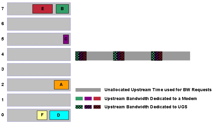
The DOCSIS compliant scheduler schedules best effort grants around the pre-scheduled UGS grants that appear as patterned blocks in Figure 12. The first action the DOCSIS compliant scheduler takes is to check the highest priority queue. In this case the priority 7 queue has grants ready to schedule. The scheduler goes ahead and allocates transmission time for grants B and E. Notice that grant E needs fragmentation so that the grant does not interfere with the timing of the pre-allocated UGS grants.
Figure 13 – Scheduling Priority 7 Grants 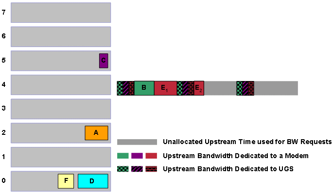
The scheduler makes sure that all priority 7 grants receive transmission time. Then, the scheduler checks the priority 6 queue. In this case, the priority 6 queue is empty so the scheduler moves on to the priority 5 queue that contains grant C.
Figure 14 – Scheduling Priority 5 Grants 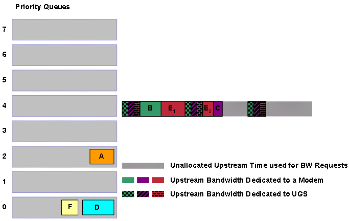
The scheduler then proceeds in a similar fashion through the lower priority queues until all the queues are empty. If there are a large number of grants to schedule, new bandwidth requests can reach the CMTS before the DOCSIS compliant scheduler finishes the allocation of transmission time to all the pending grants. Assume that the CMTS receives a bandwidth request G of priority 6 at this point in the example.
Figure 15 – A Priority 6 Grant is Queued 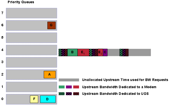
Even though grants A, F and D wait longer than the newly queued grant G, the DOCSIS compliant scheduler must next allocate transmission time to G because G has the higher priority. This means that the next bandwidth allocations of the DOCSIS compliant scheduler will be G, A then D (see Figure 16).
Figure 16 – Scheduling Priority 6 and Priority 2 Grants 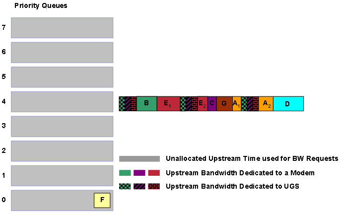
The next grant to be scheduled is F, if you assume that no higher priority grants enter the queueing system in the mean time.
The DOCSIS compliant scheduler has two more queues that have not been mentioned in the examples. The first queue is the queue used to schedule periodic station maintenance keepalive traffic in order to keep cable modems online. This queue is used to schedule opportunities for cable modems to send the CMTS periodic keepalive traffic. When the DOCSIS compliant scheduler is active, this queue is served first before all other queues. The second is a queue for grants allocated to service flows with a minimum reserved rate (CIR) specified. The scheduler treats this CIR queue as a priority 8 queue in order to ensure that service flows with a committed rate receive the required minimum throughput.
Unfragmentable DOCSIS 1.0 Grants
From the examples in the previous section, grants sometimes need to be fragmented into multiple pieces in order to ensure that jitter is not induced in pre-allocated UGS grants. This can be a problem for cable modems that operate in DOCSIS 1.0 mode on upstream segments with a significant amount of UGS traffic, because a DOCSIS 1.0 cable modem can ask to transmit a frame that is too big to fit in the next available transmission opportunity.
Here is another example, which assumes that the scheduler receives new grants A and B in that order. Also assume that both grants have the same priority but that grant B is for a cable modem that operates in DOCSIS 1.0 mode.
Figure 17 – DOCSIS 1.1 and DOCSIS 1.0 Pending Grants 
The scheduler tries to allocate time for grant A first. Then the scheduler tries to allocate the next available transmission opportunity to grant B. However, there is no room for grant B to remain unfragmented between A and the next block of UGS grants (see Figure 18).
Figure 18 – DOCSIS 1.0 Grant B Deferred 
For this reason, grant B is delayed until after the second block of UGS grants where there is room for grant B to fit. Notice that there is now unused space before the second block of UGS grants. Cable modems use this time to transmit bandwidth requests to the CMTS, but this represents an inefficient use of bandwidth.
Revisit this example and add an extra two UGS service flows to the scheduler. While grant A can be fragmented, there is no opportunity for the unfragmentable grant B to be scheduled because grant B is too big to fit between blocks of UGS grants. This situation leaves the cable modem associated with grant B unable to transmit large frames in the upstream.
Figure 19 – DOCSIS 1.0 Grant B Cannot be Scheduled 
You can allow the scheduler to simply push out, or slightly delay a block of UGS grants in order to make room for grant B but this action causes jitter in the UGS service flow. For the moment if you assume that you want to minimize jitter, this is an unacceptable solution.
In order to overcome this issue with large unfragmentable DOCSIS 1.0 grants, the DOCSIS compliant scheduler periodically pre-schedules blocks of upstream time as large as the largest frame that a DOCSIS 1.0 cable modem can transmit. The scheduler does so before any UGS service flows are scheduled. This time is typically the equivalent of about 2000 bytes of upstream transmission, and is called the “Unfragmentable Block” or the “UGS free block”.
The DOCSIS compliant scheduler does not place any UGS or RTPS style grants in the times allocated to unfragmentable traffic so as to ensure that there is always an opportunity for large DOCSIS 1.0 grants to be scheduled. In this system, reservation of time for unfragmentable DOCSIS 1.0 traffic reduces the number of UGS service flows that the upstream can simultaneously support.
Figure 20 shows the unfragmentable block in blue and four UGS service flows with the same grant size and grant interval. You cannot add another UGS service flow of the same grant size and grant interval to this upstream because UGS grants are not allowed to be scheduled in the blue unfragmentable block region.
Figure 20 – The Unfragmentable Block: No Further UGS Grants can be Admitted 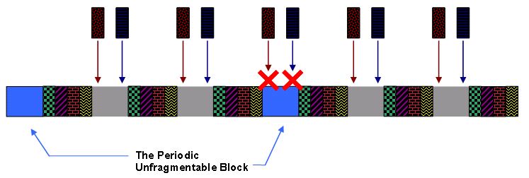
Even though the unfragmentable block is scheduled less often than the period of the UGS grants, this block tends to cause a space of unallocated bandwidth as large as itself in between all blocks of UGS grants. This provides ample opportunity for large unfragmentable grants to be scheduled.
Return to the example of grant A and DOCSIS 1.0 Grant B, you can see that with the unfragmentable block in place, the DOCSIS compliant scheduler can now successfully schedule grant B after the first block of UGS grants.
Figure 21 – Scheduling Grants with the Use of the Unfragmentable Block 
Although DOCSIS 1.0 grant B is successfully scheduled, there is still a small gap of unused space between grant A and the first block of UGS grants. This gap represents a suboptimal use of bandwidth and demonstrates why you must use DOCSIS 1.1 mode cable modems when you deploy UGS services.
Cable default-phy-burst
By default on a Cisco uBR CMTS, the largest burst that a cable modem can transmit is 2000 bytes. This value for the largest upstream burst size is used to calculate the size of the unfragmentable block as the DOCSIS compliant scheduler uses.
You can change the largest burst size with the cable default-phy-burst max-bytes-allowed-in-burst per cable interface command.
The <max-bytes-allowed-in-burst> parameter has a range of 0 to 4096 bytes and a default value of 2000 bytes. There are some important restrictions on how you must set this value if you want to change the value from the default value.
For cable interfaces on the MC5x20S line card, do not set this parameter above the default of 2000 bytes. For all other line card types, including the MC28U, MC5x20U and MC5x20H line cards, you can set this parameter as high as 4000 bytes.
Do not set the <max-bytes-allowed-in-burst> parameter lower than the size of the largest single Ethernet frame that a cable modem can need to transmit including DOCSIS or 802.1q overhead. This means that this value must be no lower than approximately 1540 bytes.
If you set <max-bytes-allowed-in-burst> to the special value of 0, the CMTS does not use this parameter to restrict the size of an upstream burst. You need to configure other variables in order to restrict the upstream burst size to a reasonable limit, such as the maximum concatenated burst setting in the DOCSIS configuration file, or the cable upstream fragment-force command.
When you modify cable default-phy-burst to change the maximum upstream burst size, the size of the UGS free block is also modified accordingly. Figure 22 shows that if you reduce the cable default-phy-burst setting, the size of the UGS free block reduces, and consequently the DOCSIS compliant scheduler can allow more UGS calls on an upstream. In this example, reduce the cable default-phy-burst from the default setting of 2000 to a lower setting of 1600 to allow room for one more UGS service flow to become active.
Figure 22 – Reduced Default-phy-burst Decreases the Unfragmentable Block Size 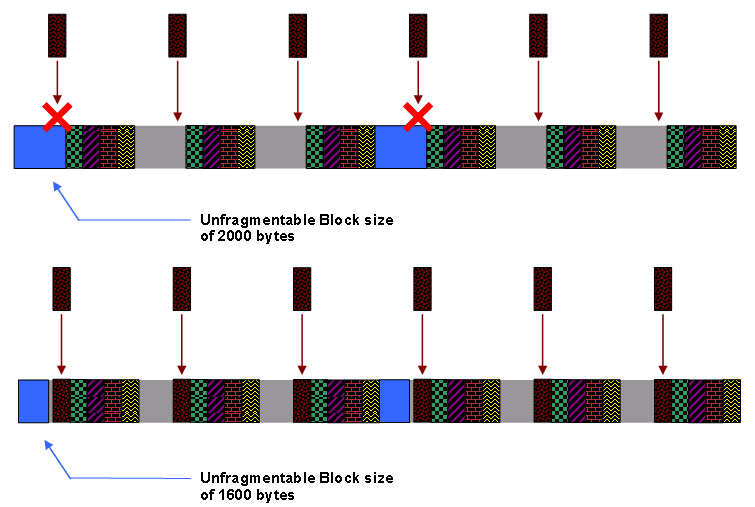
Reduction of the maximum allowable burst size with the cable default-phy-burst command can slightly decrease the efficiency of the upstream for best effort traffic, because this command reduces the number of frames that can be concatenated within one burst. Such a reduction can also lead to increased levels of fragmentation when the upstream has a larger number of UGS service flows active.
Reduced concatenated burst sizes can impact the speed of data upload in a best effort service flow. This is because transmission of multiple frames at once is faster than transmission of a bandwidth request for each frame. Reduced concatenation levels can also potentially impact the speed of downloads due to a diminished ability of the cable modem to concatenate large numbers of TCP ACK packets that travel in the upstream direction.
Sometimes, the maximum burst size as configured in the “long” IUC of the cable modulation-profile applied to an upstream, can determine the largest upstream burst size. This can occur if the maximum burst size in the modulation profile is less than the value of the cable default-phy-burst in bytes. This is a rare scenario. However, if you increase the cable default-phy-burst parameter from the default of 2000 bytes, check the maximum burst size in the configuration of the “long” IUC to ensure that it does not limit bursts.
The other limitation to upstream burst size is that a maximum of 255 minislots can be transmitted in one burst. This can become a factor if the minislot size is set to the minimum of 8 bytes. A minislot is the smallest unit of upstream transmission in a DOCSIS network and is usually equivalent to 8 or 16 bytes.
Unfragmentable Slot Jitter
Another way to tweak the DOCSIS compliant scheduler in order to permit a higher number of simultaneous UGS flows on an upstream is to allow the scheduler to let large bursts of unfragmentable best effort traffic introduce small amounts of jitter to UGS service flows. You can do so with the cable upstream upstream-number unfrag-slot-jitter limit val cable interface command.
In this command, <val> is specified in microseconds and has a default value of zero, which means that the default behavior for the DOCSIS compliant scheduler is to not allow unfragmentable grants to cause jitter for UGS and RTPS service flows. When a positive unfragmentable slot jitter is specified, the DOCSIS compliant scheduler can delay UGS grants by up to <val> microseconds from when the UGS grant must ideally be scheduled, and hence cause jitter.
This has the same effect as the reduction of the unfragmentable block size by a length equivalent to the number of microseconds specified. For example, if you maintain the default value for default-phy-burst (2000 bytes) and if you specify a value of 1000 microseconds for unfragmentable slot jitter, the unfragmentable block reduces (see Figure 23).
Figure 23 – Non-zero Unfragmentable Slot Jitter Decreases the Unfragmentable Block Size 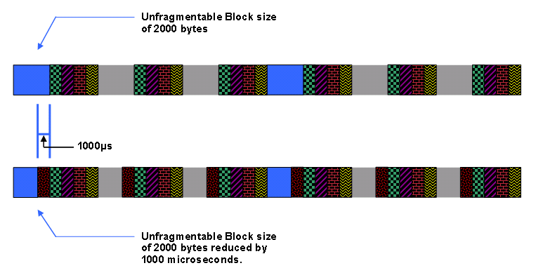
Note: The number of bytes to which the 1000-microsecond time corresponds depends on how fast the upstream channel is configured to operate through the channel width and modulation scheme settings.
Note: With a non-zero unfragmentable slot jitter the DOCSIS compliant scheduler is able to increase the number of UGS grants that an upstream supports in a similar fashion to having a reduced default-phy-burst.
Note: Return to the example with a large DOCSIS 1.1 grant A followed by a large unfragmentable DOCSIS 1.0 grant B to schedule on an upstream. You set the unfragmentable slot jitter to 1000 microseconds. The DOCSIS compliant scheduler behaves as shown in the figures in this section.
Note: First, the scheduler allocates transmission time for grant A. To do so, the scheduler fragments the grant into grants A1 and A2 so that the grants fit before and after the first block of UGS grants. In order to schedule grant B, the scheduler has to decide if the scheduler can fit the unfragmentable block into the free space after grant A2 without a delay to the next block of UGS grants by more than the configured unfragmentable slot jitter of 1000 microseconds. These figures show that if the scheduler places grant B next to grant A2, the next block of UGS traffic is delayed, or pushed back, by more than 1500 microseconds. Therefore the scheduler cannot place grant B directly after grant A2.
Figure 24 – Grant B Unable to be Scheduled Next to Grant A2. 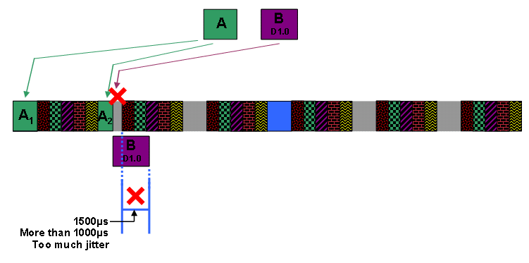
The next step for the DOCSIS compliant scheduler is to see if the next available gap can accommodate grant B. Figure 25 shows that if the scheduler places grant B after the second block of UGS grants, the third block is not delayed by more than the configured unfragmentable slot jitter of 1000 microseconds.
Figure 25 – Grant B Scheduled After the Second Block of UGS Grants 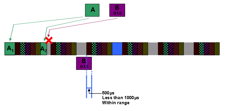
With the knowledge that insertion of grant B at this point does not cause unacceptable jitter to UGS grants, the DOCSIS compliant scheduler inserts grant B and slightly delays the following block of UGS grants.
Figure 26 – Unfragmentable Grant B is Scheduled and UGS Grants are Delayed 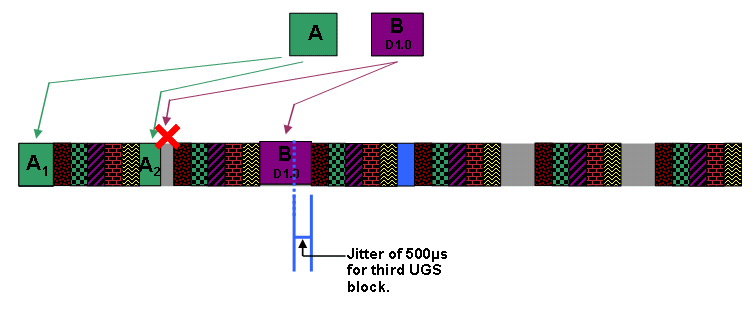
Show Command Output
You can use the show interface cable interface-number mac-scheduler upstream-number command to gauge the current status of the DOCSIS compliant scheduler. Here is an example of the output of this command as seen on a Cisco uBR7200VXR with an MC28U line card.
uBR7200VXR# show interface cable 3/0 mac-scheduler 0
     DOCSIS 1.1 MAC scheduler for Cable3/0/U0
     Queue[Rng Polls] 0/128, 0 drops, max 1
     Queue[CIR Grants] 0/64, 0 drops, max 0
     Queue[BE(7) Grants] 1/64, 0 drops, max 2
     Queue[BE(6) Grants] 0/64, 0 drops, max 0
     Queue[BE(5) Grants] 0/64, 0 drops, max 0
     Queue[BE(4) Grants] 0/64, 0 drops, max 0
     Queue[BE(3) Grants] 0/64, 0 drops, max 0
     Queue[BE(2) Grants] 0/64, 0 drops, max 0
     Queue[BE(1) Grants] 0/64, 0 drops, max 0
     Queue[BE(0) Grants] 1/64, 0 drops, max 1
     Req Slots 36356057, Req/Data Slots 185165
     Init Mtn Slots 514263, Stn Mtn Slots 314793
     Short Grant Slots 12256, Long Grant Slots 4691
     ATDMA Short Grant Slots 0, ATDMA Long Grant Slots 0
     ATDMA UGS Grant Slots 0
     Awacs Slots 277629
     Fragmentation count 41
     Fragmentation test disabled
     Avg upstream channel utilization : 26%
     Avg percent contention slots : 73%
     Avg percent initial ranging slots : 2%
     Avg percent minislots lost on late MAPs : 0%
     Sched Table Rsv-state: Grants 0, Reqpolls 0
     Sched Table Adm-State: Grants 6, Reqpolls 0, Util 27%
     UGS    : 6 SIDs, Reservation-level in bps 556800
     UGS-AD : 0 SIDs, Reservation-level in bps 0
     RTPS   : 0 SIDs, Reservation-level in bps 0
     NRTPS  : 0 SIDs, Reservation-level in bps 0
     BE     : 35 SIDs, Reservation-level in bps 0
     RTPS   : 0 SIDs, Reservation-level in bps 0
     NRTPS  : 0 SIDs, Reservation-level in bps 0
     BE     : 0 SIDs, Reservation-level in bps 0
This section explains each line of the output of this command. Note that this section of the document assumes that you are already quite familiar with general DOCSIS upstream scheduling concepts.
-
DOCSIS 1.1 MAC scheduler for Cable3/0/U0
The first line of the command output indicates the upstream port to which the data pertains.
-
Queue[Rng Polls] 0/128, 0 drops, max 1
This line shows the state of the queue which feeds station maintenance keepalives or ranging opportunities into the DOCSIS compliant scheduler. 0/128 indicates that there are currently zero out of a maximum of 128 pending ranging opportunities in the queue.
The drops counter indicates the number of times a ranging opportunity could not be queued up because this queue was already full (that is, 128 pending ranging opportunities). Drops here would only likely occur on an upstream with an extremely large number of cable modems online and if there were a large number of UGS or RTPS service flows active. This queue is serviced with the highest priority when the DOCSIS complaint scheduler runs. Therefore, drops in this queue are highly unlikely but most likely indicate a serious oversubscription of the upstream channel.
The max counter indicates the maximum number of elements present and in this queue since the show interface cable mac-scheduler command was last run. Ideally this should remain as close to zero as possible.
-
Queue[CIR Grants] 0/64, 0 drops, max 0
This line shows the state of the queue which manages grants for service flows with a minimum reserved traffic rate specified. In other words, this queue services grants for committed information rate (CIR) service flows. 0/64 indicates that there are currently zero out of a maximum of 64 pending grants in the queue.
The drops counter indicates the number of times a CIR grant could not be queued up because this queue was already full (that is, 64 grants in queue). Drops can accumulate here if the UGS, RTPS and CIR style service flows oversubscribe the upstream, and can indicate the need for stricter admission control.
The max counter indicates the maximum number of grants in this queue since the show interface cable mac-scheduler command was last run. This queue has the second highest priority so the DOCSIS compliant scheduler allocates time for elements of this queue before the scheduler services the best effort queues.
-
Queue[BE(w) Grants] x/64, y drops, max z
The next eight entries show the state of the queues that manage grants for priority 7 through 0 service flows. The fields in these entries have the same meaning as the fields in the CIR queue entry. The first queue to be served in this group is the BE (7) queue and the last to be served is the BE (0) queue.
Drops can occur in these queues if a higher priority level of traffic consumes all the upstream bandwidth or if oversubscription of the upstream with UGS, RTPS and CIR style service flows occurs. This can indicate the need to reevaluate the DOCSIS priorities for high volume service flows or a need for stricter admission control on the upstream.
-
Req Slots 36356057
This line indicates the number of bandwidth request opportunities that have been advertised since the upstream has been activated. This number must be continually on an increase.
-
Req/Data Slots 185165
Although the name suggests that this field shows the number of request or data opportunities advertised on the upstream, this field really shows the number of periods that the CMTS advertises in order to facilitate advanced spectrum management functionality. This counter is expected to increment for upstreams on MC28U and MC520 style line cards.
Request/Data opportunities are the same as bandwidth request opportunities except that cable modems are also able to transmit small bursts of data in these periods. Cisco uBR series CMTSs do not currently schedule real request/data opportunities.
-
Init Mtn Slots 514263
This line represents the number of initial maintenance opportunities that have been advertised since the upstream has been activated. This number must be continually on the rise. Cable modems that make initial attempts to establish connectivity to the CMTS use initial maintenance opportunities.
-
Stn Mtn Slots 314793
This line indicates the number of station maintenance keepalive or ranging opportunities offered on the upstream. If there are cable modems online on the upstream, this number must be continually on the rise.
-
Short Grant Slots 12256, Long Grant Slots 4691
This line indicates the number of data grants offered on the upstream. If there are cable modems that transmit upstream data, these numbers must be continually on the rise.
-
ATDMA Short Grant Slots 0, ATDMA Long Grant Slots 0, ATDMA UGS Grant Slots 0
This line represents the number of data grants offered in advanced time division multiple access (ATDMA) mode on the upstream. If there are cable modems that operate in DOCSIS 2.0 mode, and they transmit upstream data, these numbers must be continually on the rise. Note that ATDMA separately accounts for UGS traffic.
-
Awacs Slots 277629
This line shows the number of periods dedicated to advanced spectrum management. In order for advanced spectrum management to occur, the CMTS needs to periodically schedule times where each cable modem must make a brief transmission so that the internal spectrum analysis function can evaluate the signal quality from each modem.
-
Fragmentation count 41
This line shows the total number of fragments that the upstream port is scheduled to receive. For example, a frame that was fragmented into three parts would cause this counter to increment by three.
-
Fragmentation test disabled
This line indicates that the test cable fragmentation command has not been invoked. Do not use this command in a production network.
-
Avg upstream channel utilization: 26%
This line shows the current upstream channel utilization by upstream data transmissions. This encompasses transmissions made through short, long, ATDMA short, ATDMA long and ATDMA UGS grants. The value is calculated every second as a rolling average. Cisco recommends that this value not exceed 75% on an extended basis during peak usage times. Otherwise end users can start to notice performance issues with best effort traffic.
-
Avg percent contention slots: 73%
This line shows the percentage of upstream time dedicated to bandwidth requests. This equates to the amount of free time in the upstream, and therefore reduces as the Avg upstream channel utilization percentage increases.
-
Avg percent initial ranging slots: 2%
This line indicates the percentage of upstream time dedicated to initial ranging opportunities that cable modems use when they make attempts to establish initial connectivity with the CMTS. This value must always remain a low percentage of total utilization.
-
Avg percent minislots lost on late MAPs: 0%
This line indicates the percentage of upstream time that was not scheduled because the CMTS was unable to transmit a bandwidth allocation MAP message to cable modems in time. This parameter must always be close to zero but can start to show larger values on systems that have an extremely high CPU load.
-
Sched Table Rsv-state: Grants 0, Reqpolls 0
This line shows the number of UGS style service flows (Grants) or RTPS style service flows (Reqpolls) that have grants pre-allocated for them in the DOCSIS compliant scheduler, but not yet activated. This occurs when you move a cable modem with existing UGS or RTPS service flows from one upstream to another through load balancing. Note that this figure only applies to grants that use the DOCSIS compliant scheduler, and not the LLQ scheduler.
-
Sched Table Adm-State: Grants 6, Reqpolls 0, Util 27%
This line indicates the number of UGS style service flows (Grants) or RTPS style service flows (Reqpolls) that have grants pre-allocated for them in the DOCSIS compliant scheduler for this upstream. Util is the estimated utilization of the total available upstream bandwidth by these service flows. Note that this figure only applies to grants that use the DOCSIS compliant scheduler, and not the LLQ scheduler.
-
<Scheduling-type> : x SIDs, Reservation-level in bps y
This line indicates the number of <Scheduling-type> service flows or SIDs that are present on the upstream, and the amount of bandwidth in bits per second that these service flows have reserved. For best effort and RTPS style service flows, bandwidth is only reserved if the service flow has a minimum reserved rate configured.
Advantages and Disadvantages of the DOCSIS Compliant Scheduler
The goal of the DOCSIS compliant scheduler is to minimize jitter for UGS and RTPS style service flows and also accommodate unfragmentable DOCSIS 1.0 bursts. The tradeoff that the DOCSIS compliant scheduler makes in order to achieve these goals is that the maximum number of UGS service flows supported per upstream is less than the theoretical maximum that a DOCSIS upstream can physically support, and that best effort traffic can be subject to a degree of fragmentation.
While the DOCSIS compliant scheduler supports slightly less than the theoretical maximum number of concurrent UGS service flows on an upstream, and while some other scheduling implementations can support more UGS service flows per upstream, you must focus on the trade-off.
For example, no scheduler can support jitterless UGS service flows that consume close to 100% bandwidth of an upstream channel and simultaneously support large unfragmentable concatenated frames from DOCSIS 1.0 modems. In regards to the design of the DOCSIS compliant scheduler there are two important points to understand.
-
75% is the maximum desirable upstream utilization.
Cisco has found that when an upstream consistently runs at greater than 75% utilization, including utilization due to UGS service flows, best effort traffic performance starts to get noticeably affected. This means that if UGS and VoIP signaling consume more than 75% of the upstream, any normal IP traffic conveyed by best effort service flows begin to suffer from added latency that causes noticeably lower throughput and response times. This degradation of performance at higher utilization levels is a property that most modern multi-access network systems share, for example, Ethernet or Wireless LANs.
-
When the typically deployed upstream channel width of 3.2MHz is used, the DOCSIS compliant scheduler allows UGS service flows to utilize up to about 75% of the upstream channel. These service flows convey G.711 VoIP calls.
These two points give some insight into the design considerations that were taken into account when the DOCSIS compliant scheduler was built. The DOCSIS compliant scheduler was designed so that for typical UGS service flows (G.711) and with the most commonly deployed channel width of 3.2MHz, the call per upstream limits start to apply at around the 75% utilization mark. This means that the scheduler successfully minimizes jitter and also allows a reasonable number of UGS service flows in the upstream.
In other words, the DOCSIS compliant scheduler was designed to operate properly in production DOCSIS networks, and not to allow UGS service flows to use up an unrealistically high percentage of the upstream bandwidth. This scenario can occur in a contrived laboratory test scenario.
You can tweak the DOCSIS compliant scheduler to accommodate an increased number of UGS calls per upstream, albeit to the detriment of UGS jitter and best effort traffic efficiency. For this, you must reduce the cable default-phy-burst parameter to the minimum recommended setting of 1540 bytes. If you require further call density, set the cable upstream unfrag-slot-jitter to a value such as 2000 microseconds. However, Cisco does not recommend these settings generally for a production network.
Another advantage of the DOCSIS compliant scheduler is that there is no compulsory requirement that CMTS operators explicitly configure admission control for UGS and RTPS style service flows. This is because, the pre-allocation scheduling method eliminates the possibility of accidental oversubscription. Even though this is the case Cisco still suggests that operators ensure that total upstream utilization not exceed 75% for extended periods during peak hour. Therefore, Cisco recommends the configuration of admission control as a best practice.
One drawback of the DOCSIS compliant scheduler is that the fixed position of UGS grants can require the fragmentation of best effort grants when UGS utilization is high. In general, fragmentation does not cause noticeable performance problems, but does lead to a slight increase in latency for best effort traffic and an increase in protocol overhead present on the upstream channel.
Another drawback is that when DOCSIS 1.0 cable modems want to make large unfragmentable upstream transmissions there can be a delay before an appropriate gap between blocks of pre-scheduled UGS grants appears. This can also lead to increased latency for DOCSIS 1.0 upstream traffic and a less-than-optimal use of available upstream transmission time.
Finally, the DOCSIS compliant scheduler is designed to work best in environments where all UGS service flows share the same grant size and grant interval. That is, where all VoIP calls share the same codec, such as 10ms or 20ms packetization G.711 as would occur in a typical Packetcable 1.0 based system. When disparate grant intervals and sizes are present, the capacity of the DOCSIS compliant scheduler to support a high number of UGS service flows reduces on an upstream. In addition, a very small amount of jitter (less than 2ms) can occur for some grants as the scheduler tries to interleave UGS service flows with different periods and sizes.
As PacketCable MultiMedia (PCMM) networks become more prevalent it can become more common for a variety of VoIP codecs with various packetization intervals to be in simultaneous operation. This type of environment can lend itself to the Low Latency Queueing Scheduler.
The Low Latency Queueing Scheduler
The low latency queueing (LLQ) scheduler was introduced in Cisco IOS Software Release 12.3(13a)BC. LLQ is the alternative method to schedule upstream services on a Cisco uBR CMTS. This scheduler was designed to maximize the number of UGS and RTPS style service flows an upstream can support simultaneously and also enhance the efficiency of best effort traffic in the presence of UGS service flows. The trade off is the LLQ scheduler does not make any guarantees in regards to jitter for UGS and RTPS service flows.
As the DOCSIS Compliant Scheduler section discusses, the DOCSIS compliant scheduler pre-allocates transmission time in advance for UGS and RTPS style service flows. This is similar to the way a legacy time division multiplexing (TDM) system allocates bandwidth to a service to guarantee certain latency and jitter levels.
In modern packet-based networks, low latency queueing is the method that routers use to ensure that packets associated with high priority services, for example voice and video, can be delivered in a network before other lower priority packets. This is also the method that modern routers use to ensure that latency and jitter are minimized for important traffic.
The use of the word “guarantee” for the TDM-based system and “minimized” for the LLQ based system in relation to jitter and latency. While a guarantee for zero latency and jitter is desirable, the trade off is that such a system is usually inflexible, difficult to reconfigure and generally unable to easily adapt to changes in network conditions.
A system that minimizes latency and jitter, rather than providing a strict guarantee, is able to provide flexibility in order to continually optimize itself in the face of changes in network conditions. The low latency queueing scheduler behaves in a similar way to the packet-router-based LLQ system. Instead of a pre-scheduled systems of allocation for UGS grants, this system schedules the grants “as soon as possible” at the point where they need to be scheduled.
The approach that grants for UGS service flows must be allocated as soon as possible but not necessarily with perfect periodicity, this system trades off strict jitter guarantees for increased UGS capacity and less best effort data fragmentation.
Configuration
For Cisco IOS Software Releases 12.3(13a)BC and later, the LLQ scheduler is one of two alternative scheduler algorithms. You can enable LLQ for one, all or some of these scheduling modes:
-
UGS
-
RTPS
-
NRTPS
The LLQ scheduler is not enabled by default. You must explicitly turn the LLQ scheduler on for the required upstream scheduling types. Use the cable upstream upstream-port scheduling type [nrtps | rtps | ugs] mode llq cable interface command.
In general, you can enable the LLQ scheduler for all of the listed scheduling modes if this is the desired scheduling mode. Here is an example of a situation where you want to enable LLQ scheduling for only one type of scheduling mode but retain the DOCSIS compliant scheduler for others:
RTPS service flows have no strict requirement for jitter but UGS service flows do. In this case, you can enable the LLQ scheduler for RTPS service flows, and retain the DOCSIS compliant scheduler for UGS.
LLQ Scheduler Operation
The LLQ scheduler works in the same way as the priority queueing function of the DOCSIS compliant scheduler with the addition of a special low latency queue (LLQ), which takes precedence over all other queues.
The LLQ scheduler starts a timer on behalf of all active UGS (and RTPS) style service flows. The timer is set to go off once every “grant interval”. Whenever the timer expires, a UGS grant is queued in the LLQ queue. As this grant is placed in the LLQ queue that has top priority, the grant is scheduled at the next possible moment where there is free space.
The diagrams in this section show an example of a system with three active UGS service flows with the same grant interval. Figure 27 shows the timers for the UGS service flows on the left, labeled UGS-1 through UGS-3. The yellow arrow travels in a clockwise direction. When the yellow arrow points upward towards the red dot, a UGS grant is added to the LLQ Queue. You can also see the familiar eight priority queues 0 through to 7 and a new LLQ queue that takes priority over all of them. Finally, to the right, is the bandwidth allocation time line that describes how grants are scheduled on the upstream. For added clarity the bandwidth allocation time line includes a “current time” pointer. This pointer moves forward along the timeline as the example proceeds.
Figure 27 – The low latency queueing system 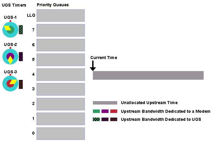
The first event that occurs is that the UGS-1 timer at the top left expires. A corresponding grant is queued in the LLQ queue. At the same time, a best effort grant called A with priority 2 is queued.
Figure 28 – The Grant for UGS-1 and the Priority 2 Grant A are Queued 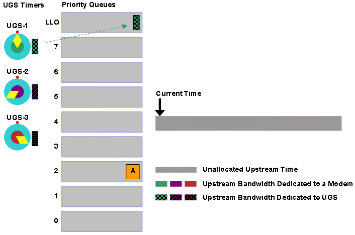
The LLQ scheduler now allocates transmission time to the pending grants in the order of priority. The first grant to receive transmission time is the grant for UGS-1 that waits in the LLQ queue. Grant A follows.
Figure 29 – Grant UGS-1 and Grant A are Allocated Transmission Time 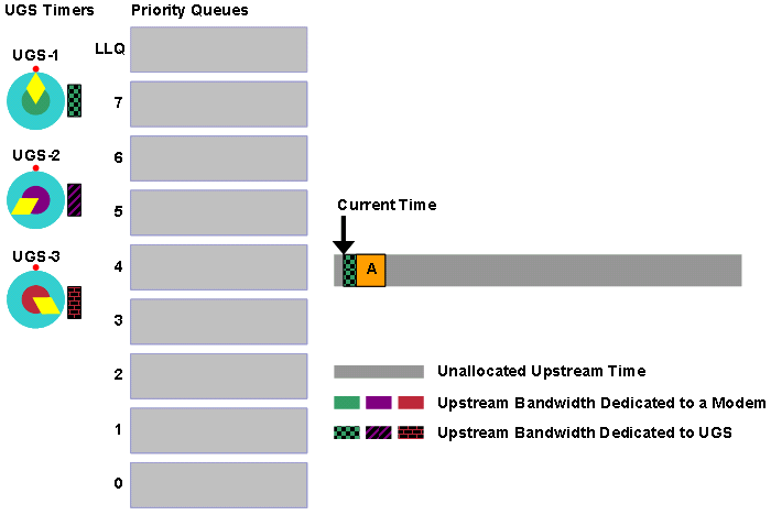
The next event to occur is that the UGS-2 timer expires and causes a grant for the UGS-2 service flow to be queued in the LLQ queue. At the same time, a priority 0 grant B is queued and priority 6 grant C is queued.
Figure 30 – UGS-2 Timer Expires. Grants B and C are Queued 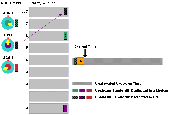
The LLQ scheduler once again allocates transmission time in the order of grant priority, which means that first the scheduler allocates time to the grant for UGS-2, then for grant C, and finally for grant B.
Figure 31 – Grants UGS-2, C and B are Allocated Transmission Time 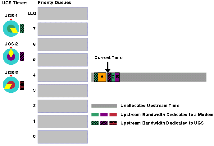
Assume that no best effort grants enter the scheduler for a while. The UGS timers each expire a few times more. You can now see the kind of period with which the scheduler allocates grants to the UGS service flows. They appear to be evenly spaced. Assume that when the grants appear this way in relation to each other on the bandwidth allocation timeline, they do not experience any significant jitter.
Figure 32 – UGS-1, UGS-2 and UGS-3 Receive a Number of Grants. Grant D is Queued 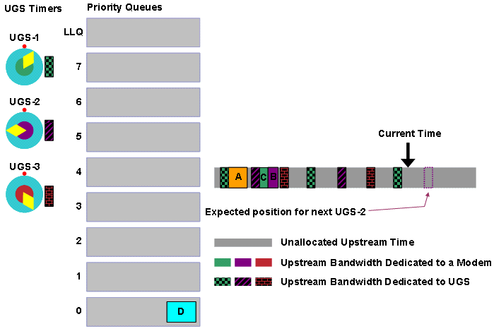
Figure 32 indicates the ideal position for the next UGS-2 grant. If UGS-2 can have the grant placed at this spot, UGS-2 will not experience any jitter for the grant. Notice that there is still time for the next UGS-2 grant to be queued in the LLQ queue.
Figure 32 also indicates that a very large priority 0 grant D has just entered the priority 0 queue. The next action the LLQ scheduler takes is to schedule transmission time for grant D.
Figure 33 displays this scenario. Wind the clock forward a little to the point where the next grant for UGS-2 is queued.
Figure 33 – Grant D Receives Transmission Time. Grant for UGS-2 is Queued 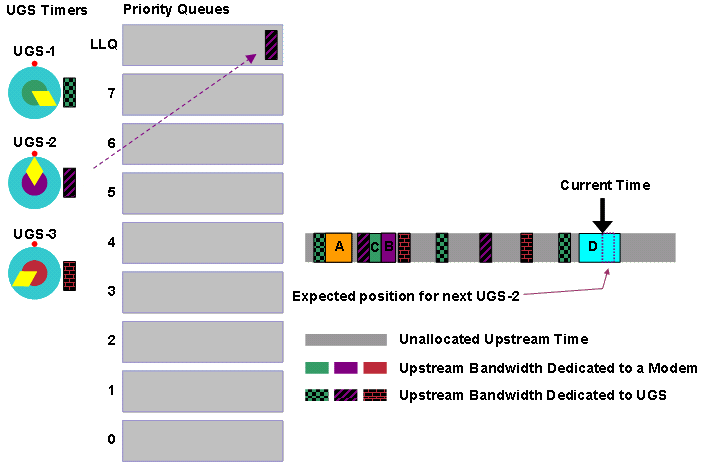
Grant D seems to be scheduled at the time when the next UGS-2 grant must be scheduled for zero jitter. Now the question is why the LLQ scheduler allows grant D to be scheduled at that point and does not delay grant D until after the grant for UGS-2 or why D is not fragmented. The answer is that the LLQ scheduler does not pre-allocate transmission time for UGS service flows. Therefore, the LLQ scheduler is not aware in advance where UGS grants will be placed on the bandwidth allocation time line. The LLQ scheduler does not know about UGS grants until they are queued in the LLQ queue. In this example, by the time the grant for UGS-2 gets into the queue, grant D is already scheduled.
The LLQ scheduler schedules the grant for UGS-2 at the next available opportunity, but this grant is slightly delayed from the ideal position, which by definition means that this particular grant experiences some jitter.
Figure 34 – Grant for UGS-2 is Delayed and Experiences Jitter 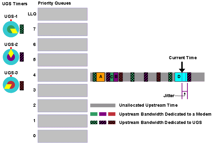
While the DOCSIS compliant scheduler could have avoided this jitter, the LLQ scheduler avoids a delay or fragmentation of grant D at the expense of only a small amount of jitter. A jitter buffer in a VoIP endpoint can easily compensate for this jitter.
The other situation where jitter can occur is when the LLQ timer for multiple service flows expires at the same time and UGS grants wait behind other UGS grants queued within the LLQ queue. The LLQ scheduler has been designed to minimize the possibility of this occurrence. The scheduler automatically spreads out the expiration times for the service flow timers.
As per the DOCSIS compliant scheduler, the LLQ scheduler has two more queues which the examples do not mention. Here are the queues:
-
The first queue is used to schedule periodic station maintenance keepalive traffic in order to keep cable modems online. This queue is served just after the LLQ queue.
-
The second is a queue for grants allocated to service flows with a minimum reserved rate (CIR service flows). This CIR queue is treated as a “priority 8” queue in order to ensure that service flows with a committed rate receive their required minimum throughput.
Admission Control
Unlike the DOCSIS compliant scheduler, the LLQ scheduler does not use a pre-scheduling system that stops accidental over-subscription of an upstream with UGS and RTPS service flows. This is why you must explicitly configure upstream admission control on any upstream that uses the LLQ scheduler. This configuration ensures that the total upstream bandwidth of UGS service flows does not exceed sane limits.
Cisco generally suggests that you do not allow the utilization of an upstream channel to exceed 75% for extended periods during peak usage periods. For example, if UGS traffic consumes more than 75% of the upstream bandwidth, best effort data starts to suffer from excessive latency and throughput performance problems.
Naturally if a CMTS operator can accept the negative consequences for best effort traffic, you can let the UGS service flows consume a higher than 75% of available upstream bandwidth. However, you must also consider the impact on the Layer 2 management traffic on the upstream channel. You must allow time for initial and station maintenance messaging (cable modem keepalives). If you do not take this into account, and UGS traffic consumes close to 100% of the bandwidth, cable modems cannot come online or can fall offline.
Here is an example configuration for admission control. This example restricts UGS service flows on a particular upstream to 50% of the available bandwidth of the upstream. This form of the command also transmits SNMP traps to any configured network management stations when the minor and major thresholds of 30% and 40% utilization are reached. The command is:
cable upstream upstream-number admission-control us-bandwidth scheduling-type UGS minor 30 major 40 exclusive 50
See the Admission Control section under the DOCSIS Compliant Scheduler section of this document for how to configure admission control.
Show Command Output
Issue the show interface cable interface-number mac-scheduler upstream-number command to gauge the current status of the LLQ scheduler.
Here is an example of the output of this command. Parts of the command output that are different from when the DOCSIS compliant scheduler is operational are in bold text:
uBR7200VXR# show interface cable 5/0 mac-scheduler 0
     DOCSIS 1.1 MAC scheduler for Cable5/0/U0
     Queue[Rng Polls] 0/128, 0 drops, max 1
     Queue[CIR Grants] 0/64, 0 drops, max 2
     Queue[BE(7) Grants] 0/64, 0 drops, max 0
     Queue[BE(6) Grants] 0/64, 0 drops, max 0
     Queue[BE(5) Grants] 0/64, 0 drops, max 0
     Queue[BE(4) Grants] 0/64, 0 drops, max 0
     Queue[BE(3) Grants] 0/64, 0 drops, max 2
     Queue[BE(2) Grants] 0/64, 0 drops, max 0
     Queue[BE(1) Grants] 0/64, 0 drops, max 0
     Queue[BE(0) Grants] 0/64, 0 drops, max 5
     Queue[LLQ Grants] 0/64, 0 drops, max 3
     Req Slots 165488850, Req/Data Slots 871206
     Init Mtn Slots 1727283, Stn Mtn Slots 1478295
     Short Grant Slots 105668683, Long Grant Slots 52721
     ATDMA Short Grant Slots 0, ATDMA Long Grant Slots 0
     ATDMA UGS Grant Slots 0
     Awacs Slots 1303668
     Fragmentation count 11215
     Fragmentation test disabled
     Avg upstream channel utilization : 6%
     Avg percent contention slots : 91%
     Avg percent initial ranging slots : 3%
     Avg percent minislots lost on late MAPs : 0%
     Sched Table Rsv-state: Grants 0, Reqpolls 0
     Sched Table Adm-State: Grants 0, Reqpolls 0, Util 1%
     UGS    : 3 SIDs, Reservation-level in bps 278400
     UGS-AD : 0 SIDs, Reservation-level in bps 0
     RTPS   : 0 SIDs, Reservation-level in bps 0
     NRTPS  : 0 SIDs, Reservation-level in bps 0
     BE     : 14 SIDs, Reservation-level in bps 0
     r4k ticks in 1ms 600000
     Total scheduling events 5009
     No search was needed 5009
     Previous entry free 0
     Next entry free 0
     Could not schedule 0
     Recovery failed 0
Curr time 1341 entry 61
Entry 188, Bin 13
    SID: 416 IUC: 5, size_ms: 17 size_byte: 232 Frag: N Inval: 20
    type 8, perfect time ref 188, skew from ref 0, priority 10
    position 188, bin 13
Entry 188, Bin 14
    SID: 414 IUC: 5, size_ms: 17 size_byte: 232 Frag: N Inval: 20
    type 8, perfect time ref 188, skew from ref 0, priority 10
    position 188, bin 14
Entry 192, Bin 12
    SID: 415 IUC: 5, size_ms: 17 size_byte: 232 Frag: N Inval: 20
    type 8, perfect time ref 192, skew from ref 0, priority 10
    position 192, bin 12
For an explanation of the plain text lines in this output, see the Show Command Output section for DOCSIS Compliant Scheduler.
Here are the descriptions for the bold lines of the show command output:
-
Queue[LLQ Grants] 0/64, 0 drops, max 3
This line shows the state of the LLQ queue, which manages grants for service flow types specified in the cable upstream scheduling type [nrtps | rtps | ugs] mode llq command. 0/64 indicates that there are currently zero out of a maximum of 64 pending grants in the queue.
The drops counter indicates the number of times the scheduler was unable to queue a UGS grant or RTPS poll because this queue was already full (in other words, when 64 grants are in queue). If drops occur in this queue, the most likely explanation is that the upstream is oversubscribed with UGS or RTPS service flows and you must apply stricter admission control.
The max counter indicates the maximum number of grants that are in this queue since the show interface cable mac-scheduler command was last run. When present, this queue has highest priority of all listed queues.
-
r4k ticks in 1ms 600000
This field represents an internal timing variable that the LLQ scheduler uses in order to ensure that grants are placed into the LLQ Queue with high precision.
-
Total scheduling events 5009
This line indicates the number of times the LLQ scheduler tries to queue a grant since the last time the show interface cable mac-scheduler command was run for this upstream. This counter is reset every time the show command is run.
-
No search was needed 5009
After the LLQ scheduler queues a grant, the LLQ scheduler tries to reset the service-flow timer to prepare for the next time a grant is queued. If there are no problems with a reset of the timer, this counter increments. This counter must ideally have the same value as the Total scheduling events counter.
-
Previous entry free 0, Next entry free 0
Neither of these counters ever increment in current releases of Cisco IOS Software. These counters always remain at zero.
-
Could not schedule 0, Recovery failed 0
This line indicates the number of times the LLQ scheduler was unable to arrange for the grant timer of a service flow to be set properly. This must only occur if the LLQ scheduler handles an extremely large number of grants with very low grant intervals. These counters are highly unlikely to ever increment on a production network. An increment of these counters can indicate that UGS and RTPS service flows consume more bandwidth than is physically available on the upstream. In this scenario, you need to implement appropriate admission control commands.
-
Curr time 1341 entry 61
This line shows internal timers for the LLQ scheduler measured in milliseconds. When the “entry” listed here equals the “Entry” field listed in the per service flow statistics, a grant is queued in the LLQ queue.
These statistics are repeated for every service flow that the LLQ scheduler handles. In this example there are three such service flows.
-
Entry 188, Bin 13
When the “Entry” value is equal to the “entry” field in the previous item, the timer for this service flow expires and a grant goes into the LLQ queue. This field resets each time the service flow has a grant queued.
-
SID: 416
The service identifier (SID) for the service flow whose grants the LLQ scheduler schedules.
-
IUC: 5
The interval usage code advertised in a MAP message for grants that belong to this service flow. This is almost always 5 for “Short data”, 6 for “Long Data” or 11 for “Advanced PHY UGS” when a UGS style service flow is in use. For RTPS style service flow, this value is always 1 for “Request”.
-
size_ms: 17 size_byte: 232
The size of the grant in minislots, followed by the size of the grant in bytes. A minislot is the smallest unit of upstream transmission in a DOCSIS network and is usually equivalent to 8 or 16 bytes.
-
Frag: N
Indicates if the grant is fragmentable. At present this value is always set to N.
-
Inval: 20
The grant or polling interval in milliseconds.
-
type 8
8 indicates this service flow is UGS, 10 indicates RTPS and 11 indicates NRTPS.
-
perfect time ref 188
The ideal time when this grant must have been scheduled. This is normally the same as “Entry” at the top. If not, there is an indication of a heavily congested upstream that needs stricter admission control.
-
skew from ref 0
The difference between when this grant has been scheduled and when the grant ideally must have been scheduled. This is the difference between “Entry” and “perfect time ref”. Therefore, this value must normally be zero.
-
priority 10
In current releases of Cisco IOS Software, this value is always set to 10, but can vary in future.
-
position 188, bin 13
These fields must be the same as “Entry, Bin” at the top of this list.
Advantages and Disadvantages of the LLQ Scheduler
The goal of the LLQ scheduler is to increase UGS and RTPS capacity for upstream channels, and to increase the efficiency of best effort traffic. The tradeoff that the LLQ scheduler makes in order to achieve these goals is that this scheduler does not explicitly give guarantees for UGS and RTPS service flow jitter. Rather, the LLQ scheduler schedules UGS grants and RTPS polls as close to the ideal time as possible with a view to minimize jitter.
The LLQ scheduler is also able to better handle multiple UGS service flows with different grant intervals and grant sizes than the DOCSIS compliant scheduler. This feature can be helpful in a PCMM environment where different types of VoIP calls and possibly other applications are all simultaneously served on the one upstream channel.
The LLQ scheduler schedules best effort traffic more efficiently because the LLQ scheduler reduces the likelihood of fragmentation of grants. When unfragmentable DOCSIS 1.0 bursts are scheduled, the LLQ scheduler does not create gaps of unused bandwidth in front of UGS grants or RTPS polls like the DOCSIS compliant scheduler sometimes does. This leads to better use of available upstream time.
Although the UGS jitter is generally higher when you use the LLQ scheduler than when you use the DOCSIS compliant scheduler, in typical DOCSIS or PacketCable-based networks, LLQ scheduler jitter levels are well within the capacity of VoIP endpoint jitter buffer technology. This means that there is no noticeable impact on VoIP call quality when you use the LLQ scheduler in a properly designed VoIP network.
You can limit jitter that arises out of large upstream bursts. For this, ensure that you keep the cable default-phy-burst parameter at the default value of 2000 bytes or less. If a system uses a particularly slow upstream channel, say with an 800 kHz or smaller channel width, you can achieve further reductions in jitter if you force large bursts to be fragmented into smaller ones with the cable upstream fragment-force command.
When the LLQ scheduler is in use, you must configure cable admission control in order to prevent the possibility of oversubscription of the upstream channel. More active UGS service flows than the upstream can physically handle, leads to poor voice quality across all UGS service flows on the upstream. In extreme cases, this also means that cable modems fall offline and new cable modems are unable to come online. Cisco recommends that CMTS operators configure admission control such that the total upstream utilization on any upstream port is not above 75% for extended periods of time.
Conclusions
The Cisco uBR series of DOCSIS CMTS products provides two alternative upstream scheduling algorithms, and so is able to cater for a variety of network conditions.
The DOCSIS compliant scheduler, which is optimized for low jitter, is most suited for typical Packetcable 1.x voice systems with a uniform VoIP codec in place and where standard levels of upstream channel utilization by UGS service flows is desired.
The Low Latency Queueing scheduler is designed to support higher-than-normal levels of upstream utilization by UGS service flows, increased best effort traffic efficiency, and systems that use UGS and RTPS service flows with a variety of grant intervals and grant sizes.
Appendix A: Minislots
A minislot is the smallest unit of transmission in the DOCSIS upstream. When a cable modem transmits a bandwidth request to the CMTS to ask for upstream transmission time, the modem asks in units of minislots rather than in bytes or milliseconds. In addition, when a bandwidth allocation MAP message informs modems of when they can transmit and for how long, the message contains the information in units of minislots.
The maximum number of minislots that a modem can request to transmit in one burst is 255. The minislot size is specified in units called DOCSIS ticks. A DOCSIS tick is the equivalent of 6.25 microseconds in time.
To set the minislot size in ticks for an upstream port, issue the cable upstream <upstream-number> minislot-size [1 | 2 | 4 | 8 | 16 | 32 | 64 | 128] cable interface command.
Only certain minislot sizes are allowed with particular upstream channel widths. This table shows valid minislot sizes versus DOCSIS upstream channel widths, and also shows the length in modulation scheme symbols of a minislot with valid settings.
Note: An X mark signifies an invalid combination.
| Channel Width | 200 kHz | 400 kHz | 800 kHz | 1.6 MHz | 3.2 MHz | 6.4 MHz | |
|---|---|---|---|---|---|---|---|
| Minislot Size in ticks | |||||||
| 1 | X | X | X | X | X | 32 | |
| 2 | X | X | X | X | 32 | 64 | |
| 4 | X | X | X | 32 | 64 | 128 | |
| 8 | X | X | 32 | 64 | 128 | 256 | |
| 16 | X | 32 | 64 | 128 | 256 | X | |
| 32 | 32 | 64 | 128 | 256 | X | X | |
| 64 | 64 | 128 | 256 | X | X | X | |
| 128 | 128 | 256 | X | X | X | X |
To calculate the number of bytes transmitted per minislot, multiply the symbols per minislot by the number of bits per symbol for the configured modulation scheme. Different modulation schemes transmit different numbers of bits per symbol as shown in this table:
| DOCSIS 1.1 TDMA Modulation Schemes | Bits per Symbol |
|---|---|
| QPSK | 2 |
| 16-QAM | 4 |
| DOCSIS 2.0 ATDMA Modulation Schemes | Bits per Symbol |
|---|---|
| 8-QAM | 3 |
| 32-QAM | 5 |
| 64-QAM | 6 |
For example, with a 1.6 MHz channel width and minislot size of 4 ticks, you can use the first table to arrive at a figure of 32 symbols per minislot. Use the second table to convert this figure into bytes, because a QPSK symbol contains 2 bits. One minislot in this example is equivalent to 32 symbols per minislot * 2 bits per symbol = 64 bits per minislot = 8 bytes per minislot.
Remember that the maximum number of minislots a cable modem can request to transmit is 255. Therefore, in this example upstream the largest burst in bytes that a modem can make is 255 minislots * 8 bytes per minislot = 2040 bytes.
Note that this figure in bytes is the post forward error correction and post physical layer overhead figure. Error correction and other DOCSIS PHY layer overhead adds about 10 to 20 percent to the length of an Ethernet frame as it passes through the upstream channel. To derive the precise figure, use the modulation profile applied to the upstream port.
This discussion is significant because an earlier section of this document states that one of the limits on the maximum burst size of a cable modem is the value configured in the cable default-phy-burst command. If the cable default-phy-burst command is set to 4000 bytes in the context of this example, the limiting factor or burst size is the 255 minislot limit (2040 bytes minus overhead) rather than the cable default-phy-burst value.
You can observe different expressions of the minislot size for an upstream with the show controller cable interface-number upstream upstream-number command. Here is an example:
uBR7200VXR# show controller cable 5/0 upstream 0
 Cable5/0 Upstream 0 is up
  Frequency 20.600 MHz, Channel Width 1.600 MHz, QPSK Symbol Rate 1.280 Msps
  This upstream is mapped to physical port 0
  Spectrum Group 1, Last Frequency Hop Data Error: NO(0)
  MC28U CNR measurement : better than 40 dB
  US phy MER(SNR)_estimate for good packets - 36.1280 dB
  Nominal Input Power Level 0 dBmV, Tx Timing Offset 3100
  Ranging Backoff Start 3, Ranging Backoff End 6
  Ranging Insertion Interval automatic (60 ms)
  US throttling off
  Tx Backoff Start 3, Tx Backoff End 5
  Modulation Profile Group 41
  Concatenation is enabled
  Fragmentation is enabled
  part_id=0x3138, rev_id=0x03, rev2_id=0x00
  nb_agc_thr=0x0000, nb_agc_nom=0x0000
  Range Load Reg Size=0x58
  Request Load Reg Size=0x0E
  Minislot Size in number of Timebase Ticks is = 8
  Minislot Size in Symbols = 64
  Bandwidth Requests = 0x338C
  Piggyback Requests = 0x66D
  Invalid BW Requests= 0xD9
  Minislots Requested= 0x756C2
  Minislots Granted  = 0x4E09
  Minislot Size in Bytes = 16
  Map Advance (Dynamic) : 2482 usecs
  UCD Count = 8353
Cisco recommends that you set the minislot size such that a minislot is equivalent to 16 bytes or the closest allowable value. A minislot size of 16 bytes gives cable modems the ability to generate a post FEC burst of up to 255 * 16 = 4096 bytes.
Appendix B: MAP Advance
The CMTS periodically generates a special message called a bandwidth allocation MAP that informs cable modems of a precise time when modems can make transmissions on the upstream channel. The electrical signals that convey the MAP message take a finite amount of time to physically propagate through the hybrid fiber coax (HFC) network from the CMTS to all connected cable modems. As a result, the MAP message needs to be transmitted early enough for the modems to receive the message and be able to make their upstream transmissions so that they reach the CMTS at the designated time.
The MAP advance time or the MAP look ahead time represents the difference between the time when the CMTS generates the MAP message and the time when the first transmission ordered by the MAP needs to be received by the CMTS. This time represents a combination of these delays present in a DOCSIS system:
-
The time that the CMTS takes to construct the MAP message in software and for the message to be queued to and processed by the downstream transmission circuitry. The value of this component is specific to different platforms and architectures and is generally a fixed value.
-
The latency that the downstream interleaving function adds, which is used for forward error correction purposes to guard against impulse noise. To change this value, change the downstream interleaver parameters.
-
The time that electrical signals take to travel through the HFC network from the CMTS to the cable modem and then back again. DOCSIS specifies a maximum one-way-trip-time between the CMTS and cable modem of 800 microseconds. This value varies depending on the physical length of the cable plant. The downstream modulation scheme and the upstream channel width and modulation scheme also influence this value.
-
The time for the cable modem to process a received MAP message and be able to prepare for upstream transmission. This must be no more than 200 microseconds plus any upstream interleaver delay as per the guidelines in the DOCSIS specification. In reality this time can be as high as 300 microseconds or as low as 100 microseconds depending on the make, model and firmware revision of cable modem.

The map advance time can significantly affect the latency of upstream transmissions because this value represents the minimum delay between the time when the CMTS knows that a cable modem wants to make a transmission and the time when the modem is allowed to make that transmission. For this reason, minimize the map advance time to reduce upstream latency.
Note that in a congested upstream, other factors also influence upstream latency. For example, delays that the backoff and retry bandwidth request algorithm causes, and the queueing of pending grants behind one another.
Figure 36 shows the relationship between a MAP that the CMTS generates and the corresponding data receipt at the upstream.
Figure 36 – Relationship Between MAP Generation and Receipt of Upstream Data 
Interleaver Depth
The first factor in the map advance time that can vary is the downstream interleaver as used for impulse noise protection. This table shows the latency added to downstream transmissions for various interleaver tap and interleaver increment settings:
Note: The larger the tap size, the more powerful the error correction, but also the larger is the induced latency.
| I (Number of Taps) | J (Increment) | Latency 64-QAM | Latency 256-QAM |
|---|---|---|---|
| 8 | 16 | 220 µsec | 150 µsec |
| 16 | 8 | 480 µsec | 330 µsec |
| 32 | 4 | 980 µsec | 680 µsec |
| 64 | 2 | 2000 µsec | 1400 µsec |
| 128 | 1 | 4000 µsec | 2800 µsec |
| 12 (EuroDOCSIS) | 17 (EuroDOCSIS) | 430 µsec | 320 µsec |
You can set the interleaver parameters with the cable downstream interleave-depth [8 | 16 | 32 | 64 | 128] cable interface configuration command
Note: The value for I (number of taps) is specified and a fixed corresponding value for J (increment) as seen in the table automatically applies. Also, for EuroDOCSIS (Annex A) mode the interleaver parameters are fixed at I = 12 and J = 17. The default value for I is 32, which gives a default value for J of 4.
Round Trip Time
The second factor that contributes to map advance time that can be varied is the electrical round trip time between the CMTS and cable modems. The physical distance between the CMTS and cable modems and the processing delay inherent in the cable modems influence this value.
The DOCSIS specification mandates that the maximum allowable one way propagation time between the CMTS and the furthest cable modem in the system be no more than 800 microseconds. This implies a round trip time, excluding cable modem processing delay, of about 1600 microseconds.
The speed of light in a vacuum is approximately 186,000 miles per second (300,000 kilometers per second) and the velocity of propagation for fiber is typically quoted as 0.67. Therefore, the maximum allowable one way distance between a CMTS and a cable modem is approximately:
	Distance = Velocity * Time

       		 = (186,000 miles/sec * 0.67) * 800 microseconds

       		 = 100 miles or 161 kilometers.
According to the DOCSIS specification the cable modem processing delay must not exceed 200 microseconds plus any upstream interleaving delay. However, in rare cases, some older brands of cable modem can take as long as 300 microseconds to process a MAP message. Newer types of cable modems with more powerful CPUs can take as little as 100 microseconds to process a MAP message.
Assume that cable modems are, on average, compliant with the DOCSIS specification. Therefore, the maximum round trip time must be 1600 + 200 = 1800 microseconds.
The majority of cable systems are much shorter than 100 miles. Therefore it is not optimal for a CMTS to always assume that the electrical round trip time between the CMTS and the furthest cable modem is the maximum value of 1800 microseconds.
For a rough estimate for the largest expected electrical round trip time, add up the distance of fiber between the CMTS and cable modem and multiply by 16 microseconds per mile (10 microseconds per km). Then add up the distance of any coax and multiply that value by 12.4 microseconds per mile (7.6 microseconds per km). Then add the 200 microsecond processing delay.
For example, an HFC segment with a total of 20 miles of fiber and one a mile of coax between the CMTS and the furthest cable modem could expect an electrical round trip delay of:
20 miles * 16 microseconds/mile + 1 mile * 12.4 microseconds/mile + 200 microseconds

= 320 microseconds + 12.4 microseconds + 200 microseconds

= 532.4 microseconds
This figure does not take into account extra delays due to upstream and downstream channel characteristics and variations in modem processing times. Therefore this value is not appropriate to use when you calculate the MAP advance time.
A more accurate way to determine the round trip time in a system is to observe the “Timing Offset” for cable modems as seen in the output of the show cable modem command.As a part of the ranging process that cable modems use to maintain communication with the CMTS, the CMTS calculates the round trip time for each cable modem. This round trip time appears as the “Timing Offset” in the show cable modem command output in units of 1/10.24MHz = 97.7 nanoseconds called timing offset or ranging offset units. To convert the timing offset for a modem to microseconds, multiply the value by 25/256, or very roughly divide the value by 10.
Here is an example in which the timing offsets of various modems in the show cable modem command output are converted to a microsecond value:
Note: The microsecond value appears in italics.
uBR7200VXR# show cable modem
MAC Address    IP Address   I/F       MAC         Prim RxPwr Timing  Num BPI
                                      State       Sid  (dB)  Offset  CPE Enb
00aa.bb99.0859 4.24.64.28   C5/1/U0   online(pt)  16   0.00  2027     0   Y  (198μs)
00aa.bb99.7459 4.24.64.11   C5/1/U0   online(pt)  17   1.00  3528     0   Y  (345μs)
00aa.bbf3.7258 4.24.64.31   C5/1/U0   online(pt)  18   0.00  2531     0   Y  (247μs)
00aa.bbf3.5658 4.24.64.39   C5/1/U0   online(pt)  19   0.00  6030     0   Y  (589μs)
In this case, the furthest modem away electrically is the last modem with a timing offset of 6030. This equates to a round trip time of 6030 * 25/256 = 589 microseconds.
Static MAP Advance
In a system where you know that the length of the HFC network is significantly less than 100 miles, you can configure the CMTS to use a maximum round trip time that is less than the standard 1800 microseconds when you calculate the MAP advance time.
To force the CMTS to use a custom value for round trip time in the MAP advance calculation, issue the cable map-advance static max-round-trip-time cable interface command.
The range for max-round-trip-time is 100 to 2000 microseconds. If no value is specified for max-round-trip-time, the default of 1800 microseconds applies.
Note: You can replace the static keyword with the dynamic keyword. See the next section.
Make sure that the specified round-trip-time is indeed larger than the greatest CMTS to cable modem round trip time on the downstream channel. If a cable modem has a larger round trip time than that specified in max-round-trip-time, the modem can find it difficult to stay online. This is because such a modem does not have sufficient time to respond to a MAP message and therefore is unable to communicate with the CMTS.
If the time offset of a cable modem, converted to microseconds, exceeds the specified max-round-trip-time, the modem is marked with the bad timing offset flag. This offset flag appears as an exclamation mark (!) next to the timing offset of the cable modem in the show cable modem command output. This situation can occur if the max-round-trip-time parameter is set too low or if the cable modem suffers from a problem where its timing offset is unstable and constantly increases over time.
Here is an example:
uBR7200VXR# show cable modem
MAC Address    IP Address   I/F      MAC         Prim RxPwr  Timing  Num BPI
                                     State       Sid  (dB)   Offset  CPE Enb
00aa.bb99.0859 4.24.64.28   C5/1/U0  online(pt)  16   0.00  2027     0   Y  (198μs)
00aa.bb99.7459 4.24.64.11   C5/1/U0  online(pt)  17   1.00  3528     0   Y  (345μs)
00aa.bbf3.7258 4.24.64.31   C5/1/U0  online(pt)  18   0.00  2531     0   Y  (247μs)
00aa.bbf3.5658 4.24.64.39   C5/1/U0  online(pt)  19   0.00  !5120    0   Y  (500μs)
In this example, the cable map-advance static 500 command is specified. However, one of the cable modems connected to the cable interface has a timing offset of greater than 500 microseconds (equivalent to 500 * 256/25 = 5120 timing offset units).
Note that the timing offset of the last cable modem is marked with the bad timing offset flag, a “!”. This is also fixed to the maximum allowed value of 5120 units even though the true timing offset can be much higher. This cable modem can go offline and suffer from poor performance.
The bad timing offset flag remains set for the cable modem even if the timing offset falls below the max-round-trip-time. The only way to clear the flag is to remove the modem temporarily from the show cable modem list. For this, you can use the clear cable modem mac-address delete command. Alternatively, you can reset the cable interface or upstream port.
To observe the operation of the static map advance algorithm on a per upstream basis, issue the show controller cable interface-number upstream upstream-number command. Here is an example:
uBR7200VXR# show controller cable 5/0 upstream 0
 Cable5/0 Upstream 0 is up
  Frequency 20.600 MHz, Channel Width 1.600 MHz, QPSK Symbol Rate 1.280 Msps
  This upstream is mapped to physical port 0
  Spectrum Group is overridden
  US phy MER(SNR)_estimate for good packets - 36.1280 dB
  Nominal Input Power Level 0 dBmV, Tx Timing Offset 2037
  Ranging Backoff automatic (Start 0, End 3)
  Ranging Insertion Interval automatic (60 ms)
  US throttling off
  Tx Backoff automatic (Start 0, End 3)
  Modulation Profile Group 43
  Concatenation is enabled
  Fragmentation is enabled
  part_id=0x3138, rev_id=0x03, rev2_id=0x00
  nb_agc_thr=0x0000, nb_agc_nom=0x0000
  Range Load Reg Size=0x58
  Request Load Reg Size=0x0E
  Minislot Size in number of Timebase Ticks is = 16
  Minislot Size in Symbols = 128
  Bandwidth Requests = 0x6ECEA
  Piggyback Requests = 0xDE79
  Invalid BW Requests= 0x63D
  Minislots Requested= 0x8DEE0E
  Minislots Granted  = 0x7CE03
  Minislot Size in Bytes = 32
  Map Advance (Static) : 3480 usecs
  UCD Count = 289392
The Map Advance (Static) field shows a map advance time of 3480 microseconds. If you change the downstream interleaver characteristics or the max-round-trip-time parameter, the change is reflected in the static map advance value.
Dynamic MAP Advance
The use of the static MAP advance calculation to optimize MAP advance times requires the CMTS operator to manually determine the largest round trip time on a cable segment. If any downstream or upstream channel characteristics change, or if any plant conditions change, the maximum round trip time can change significantly. It can be difficult to continually update the configuration to accommodate the change in system conditions.
The dynamic MAP advance algorithm solves this problem. The dynamic MAP advance algorithm periodically scans the show cable modem list to search for the modem with the largest initial ranging timing offset, and then automatically uses that value to calculate the MAP advance time. Thus, the CMTS always uses the lowest possible map advance time.
The initial ranging timing offset for a cable modem is the timing offset that the modem reports at the point where the modem comes online. In most cases, this is close to the on going timing offset as seen in the show cable modem command output. However, some types of cable modems have a problem where the timing offset creeps upwards over time to very large values. This can skew the map advance time calculation. So only the initial ranging timing offset, which is only updated if a modem comes online, is used. To view the initial ranging timing offset and the ongoing timing offset for a cable modem, issue the show cable modem verbose command. Here is an example:
uBR7200VXR# show cable modem 00aa.bbf3.7858 verbose
MAC Address                         : 00aa.bbf3.7858
IP Address                          : 4.24.64.18
Prim Sid                            : 48
Interface                           : C5/1/U0
Upstream Power                      : 39.06 dBmV (SNR = 36.12 dB)
Downstream Power                    : 14.01 dBmV (SNR = 35.04 dB)
Timing Offset                       : 2566
Initial Timing Offset               : 2560
Received Power                      :  0.00 dBmV
MAC Version                         : DOC1.1
QoS Provisioned Mode                : DOC1.1
Enable DOCSIS2.0 Mode               : Y
Phy Operating Mode                  : tdma
Capabilities                        : {Frag=Y, Concat=Y, PHS=Y, Priv=BPI+}
Sid/Said Limit                      : {Max US Sids=16, Max DS Saids=15}
Optional Filtering Support          : {802.1P=N, 802.1Q=N}
Transmit Equalizer Support          : {Taps/Symbol= 1, Num of Taps= 8}
Number of CPE IPs                   : 0(Max CPE IPs = 16)
CFG Max-CPE                         : 32
Flaps                               : 4(Mar 13 21:13:50)
Errors                              : 0 CRCs, 0 HCSes
Stn Mtn Failures                    : 0 aborts, 1 exhausted
Total US Flows                      : 1(1 active)
Total DS Flows                      : 1(1 active)
Total US Data                       : 321 packets, 40199 bytes
Total US Throughput                 : 129 bits/sec, 0 packets/sec
Total DS Data                       : 28 packets, 2516 bytes
Total DS Throughput                 : 0 bits/sec, 0 packets/sec
Active Classifiers                  : 0 (Max = NO LIMIT)
DSA/DSX messages                    : permit all
Total Time Online                   : 1h00m
In this example, the ongoing time offset (2566) is slightly higher than the initial ranging timing offset (2560). These values can differ slightly. However, if the values differ by more than a few hundred units, there can be a problem with the timing offset control of the cable modem.
To activate the dynamic map advance calculation, issue the cable map-advance dynamic safety-factor max-round-trip-time cable interface command.
The safety-factor parameter ranges from 100 to 2000 microseconds. This parameter is added to the MAP advance time so as to provide a small safeguard to account for any extra unanticipated delays in signal propagation. The default value is 1000 microseconds. However, for stable cable systems that do not undergo significant changes in the cable plant or in upstream or downstream channel characteristics, use a lower value such as 500 microseconds.
The max-round-trip-time parameter ranges from 100 to 2000 microseconds. This parameter is used as an upper limit for the time offsets of cable modems connected to the cable segment. The default value is 1800 microseconds. If the time offset of a cable modem, converted to microseconds, exceeds the specified max-round-trip-time, it appears marked with the bad timing offset flag.
Set the max-round-trip time parameter to a non default value when you know that the length of the cable system is significantly less than 100 miles, and if you know what must be the maximum normal time offset for cable modems connected to the segment.
Observe the operation of the dynamic map advance algorithm on a per upstream basis with the show controller cable interface-number upstream upstream-number command. Here is an example:
uBR7200VXR# show controller cable 5/0 upstream 0
 Cable5/0 Upstream 0 is up
  Frequency 20.600 MHz, Channel Width 1.600 MHz, QPSK Symbol Rate 1.280 Msps
  This upstream is mapped to physical port 0
  Spectrum Group 1, Last Frequency Hop Data Error: NO(0)
  MC28U CNR measurement : better than 40 dB
  US phy MER(SNR)_estimate for good packets - 36.1280 dB
  Nominal Input Power Level 0 dBmV, Tx Timing Offset 3100
  Ranging Backoff Start 3, Ranging Backoff End 6
  Ranging Insertion Interval automatic (60 ms)
  US throttling off
  Tx Backoff Start 3, Tx Backoff End 5
  Modulation Profile Group 41
  Concatenation is enabled
  Fragmentation is enabled
  part_id=0x3138, rev_id=0x03, rev2_id=0x00
  nb_agc_thr=0x0000, nb_agc_nom=0x0000
  Range Load Reg Size=0x58
  Request Load Reg Size=0x0E
  Minislot Size in number of Timebase Ticks is = 8
  Minislot Size in Symbols = 64
  Bandwidth Requests = 0x338C
  Piggyback Requests = 0x66D
  Invalid BW Requests= 0xD9
  Minislots Requested= 0x756C2
  Minislots Granted  = 0x4E09
  Minislot Size in Bytes = 16
  Map Advance (Dynamic) : 2482 usecs
  UCD Count = 8353
The Tx Timing Offset value shows the largest timing offset for all cable modems connected to the upstream in timing offset units. Use this value to calculate the MAP advance time. The Map Advance (Dynamic) field shows the resultant map advance time. This value can vary if the Tx Timing Offset changes, if the safety-value is modified, or if the downstream interleaver characteristics are changed.
The dynamic MAP advance algorithm depends on whether cable modems report their initial ranging timing offset to the CMTS correctly. Unfortunately, some makes and models of cable modems report the initial ranging timing offsets as values that are significantly lower than the true value. You can observe this when modems show timing offsets that are close to zero or even negative values.
Error messages similar to %UBR7200-4-BADTXOFFSET: Bad timing offset -2 detected for cable modem 00ff.0bad.caf3 can appear on such cable modems. These types of cable modems do not report their timing offsets in a DOCSIS compliant way, the dynamic map advance algorithm cannot correctly calculate a map advance time that is guaranteed to give every cable modem time to receive and respond to MAP messages.
If such cable modems are present on a cable segment, disable the dynamic MAP advance algorithm and revert to the static MAP advance algorithm. Refer to Why Do Some Cable Modems Display a Negative Time Offset? for more information.
Related Information
Revision History
| Revision | Publish Date | Comments |
|---|---|---|
1.0 |
03-Apr-2006 |
Initial Release |
Contact Cisco
- Open a Support Case

- (Requires a Cisco Service Contract)
 Feedback