N+1 Redundancy Using the Cisco RF Switch
Available Languages
Contents
Introduction
This document provides information on N+1 redundancy using the Cisco® RF Switch.
Prerequisites
Requirements
There are no specific requirements for this document.
Components Used
This document is not restricted to specific software and hardware versions.
The information in this document was created from the devices in a specific lab environment. All of the devices used in this document started with a cleared (default) configuration. If your network is live, make sure that you understand the potential impact of any command.
Conventions
For more information on document conventions, see the Cisco Technical Tips Conventions.
Background Information
To get the most value for their money, many cable operators have decided to provide redundancy for their fiber optic network in the form of extra backup power supplies in the fiber node, uninterruptible power supplies (UPS) with natural gas and battery backup, and extra fiber transmitters in the node. Extra dark fibers could also be allocated to each node in the event of a fiber failure.
As explained above, hardware is the first thing to cover in the outside plant. What about the actual upstream (US) and downstream (DS) signals traveling on the transportation medium? In regards to US, Cisco has implemented Advanced Spectrum Management techniques to keep the modems online and transmitting optimally. Some of these techniques are frequency hopping with advanced "look before you leap" capability via the on-board spectrum analyzer daughter card on the S-card. Cisco also incorporated modulation profile changes and channel width changes. All these features allow the modem to stay in a clean part of the spectrum, use a more robust modulation profile, and/or change channel-width to keep the service optimized in regards to throughput and availability. When looking at DS frequencies, you have a choice of either 64 or 256-QAM. While these modulation schemes are much less robust than the US at QPSK or 16-QAM, the DS spectrum is much more predictable and under control than the US spectrum.
Hardware availability in the headend is the next logical thing to focus on. If a single source of AC or DC fails, generator back-up may be used with redundant power supplies in case one goes bad.
Another hardware point-of-failure could be the Cable Modem Termination System (CMTS) powering. The uBR10K power supplies utilize an algorithm for back-up and load-balance/sharing. This is sometimes referred to as N:1, which means 1 for N back-up with load balancing. In this case, it will be 1:1, and you will notice that the total DC power is slightly more, with two power entry modules (PEMs), than if one were used for the entire load. Issue the sh cont clock-reference command to view this information.
ubr10k#sh cont clock-reference | inc Power Entry
Power Entry Module 0 Power:                     510w
Power Entry Module 0 Voltage:                   51v
Power Entry Module 1 Power:                     561w
Power Entry Module 1 Voltage:                   51v
To focus on the availability of CMTS linecards, Cisco has developed a protocol to specify how CMTSs will communicate with each other in a high-availability scenario. This protocol is called Hot Standby Connection-to-Connection Protocol (HCCP). This protocol provides a heartbeat between the protect device and working device(s) to keep the interfaces/devices synchronized with MAC tables, configurations, and so on. Cisco has also developed an RF Switch to provide high-availability at the MAC domain level instead of chassis for chassis. A MAC domain can also be thought of as an RF subnet, which is one DS and all of its associated USs.
Cisco has offered 1+1 redundancy on the uBR7200 series chassis for a few years, however, an entire chassis must sit idle as a protect chassis. The advantage of doing 1+1 is no RF Switch is needed, but less scalable. The use of an RF Switch allows redundancy to be done at the interface level for N+1 availability. This means 1 for N back-up without load balancing/sharing. Instead of an entire chassis sitting idle, you may have one idle/ protect card or interface protecting many other interfaces. The uBR100012 can be setup as one card protecting seven others. This helps with economics because it now provides 7+1 availability, and also passes necessary requirements for PacketCable.
After these points are covered, you want to be certain that you have redundancy for the backhaul side, also known as the WAN or LAN side, depending on how you look at it. Hot Standby Router Protocol (HSRP) has been around for years, and allows redundant paths between routers to provide a level of availability needed for this single-point-of-failure. The real push for these features is VoIP and increased competitive pressures to provide the most stable/available service to the customer.
Operational Sequence of Events
uBR10K Solution
HCCP happens first between the chassis via the heartbeat. Since the uBR10K solution is all contained in one chassis, the heartbeat may not be relevant. If internal communication and interface changes are successful, then HCCP will continue to send a command to the RF Switch to toggle the appropriate relays.
uBR7200 Solution
HCCP happens first between the chassis via the heartbeat. A command is then sent from the protect 7200 to the upconverter (UPx) to change frequency. The UPx sends an ACK. The protect 7200 sends a command to disable the working UPx module and waits for an ACK. The protect 7200 then sends a command to enable the protect UPx module and waits for an ACK. If all this works or no ACK is sent from the working UPx module, then it will continue and send a command to the switch to toggle the appropriate relays.
There are two types of heartbeat mechanisms that are relevant to HCCP. They are listed below.
-
helloACK between the working and protect — The protect LC sends a hello message to each of the working LCs in its group, and expects a helloACK in response. The sending frequency of the hello and helloACK is configurable on the protect LC with CLI. Further, the minimum hello time on the 7200 is 0.6 seconds, while the minimum on the uBR10K is 1.6 sec.
-
Sync pulse mechanism — This is an HCCP data-plane heartbeat mechanism, and its frequency is not configurable. The sync pulses are sent by each working LC to its peer protect LC. This sync pulse is sent once per second. If three sync pulses are missed, the peer is declared down. Cisco is working on a fast fault detection mechanism to detect a working crash in the exception handler in less than 500 msec. The target release is 12.2(15)BC. On the VXR, failure can be detected by both mechanisms, however, since the uBR10K is all internal HCCP, only the second one is relevant.
RF Switch
Cisco decided on an external RF Switch as opposed to a linecard or internal wiring that would operate as an RF Switch because of future scalability and complexity. The external switch can be stacked and used for multiple scenarios, different densities, and legacy equipment.
There are 252 connections on the back of the switch in a 3 rack unit (3RU) package. 1RU is 1.75 inches. The VCom HD4040 upconverter is 2RU.
If the backplane is configured a certain way for an internal switch, you limit the flexibility to do different linecard densities later down the road. If a linecard is too dense, then too many US ports are affected by failures that are specific to a single US or DS and card in general. That is why a switch and redundancy is needed from the start. More density equals more customers that are affected by a single event. What happens if pure DS cards and pure US cards are sold? In the future, you will be able to match US and DS ports across linecards. The external design protects my investment further in the future.
You will never be able to do redundancy between chassis with an internal switch. If you want to save money and have four 7200 uBRs backed up by one, an external RF Switch is needed. Unless, you are thinking about having linecards in a chassis backed up by another in the same chassis. The only problem is if the whole chassis goes down, you have no backup.
The availability numbers may be better for an external switch (at least concerning the electronics, not the cabling) because of less active components. Since the switch has a total passive design in the chassis, normal working mode is operational, even if the active modules are removed. The relays are only located on the protect path with a totally passive working path, and can be toggled to test the switch without affecting the actual working mode. This means that the normal working mode will not be affected by a power failure on the switch, a switch module being pulled out, or a switch failure. The one negative from this is the insertion loss of potentially 6 to 8 dB at the highest DS frequency of 860 MHz.
The external design also allows cabling migration and linecard swap-outs. If someone wants to upgrade from a 2x8 card to a 5x20 card, the linecard can be forced to failover to the protect mode. The linecard can be changed out at a pace that you determine with the newer, denser 5x20 card and wired up for future domains. The two domains that were in the protect mode will then be switched back to the corresponding interface/ domains on the 5x20 card. Other issues must be addressed, such as the 5x20 will have internal upconverters and connector commands.
The front panel has the LEDs, power cord for AC or DC, Ethernet connectivity, RS-232 connectivity, and a power switch to designate AC, DC, or off. A cable extraction tool is shipped with each switch also. Be sure to remove the rubber boot before usage. The extraction force can be adjusted with a screw driver by screwing in clockwise on the back of the tool.
The picture below is the front view of the RF Switch.
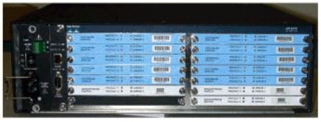
There are ten US (shown in blue) and three DS (shown in gray) modules installed in the 3x10 RF Switch. The bottom left is known as module N and is blank. The modules on the front, starting from the upper right corner, are numbers 1-13, and correlate to the ports A-M. Upstream Module 1 has all the relays for port A in slots 1 through 8 and protect 1 and 2 on the back. Module 2 is on the left and has all the relays for port H in slots 1 through 8 and protect 1 and 2.
The modules can be hot-swapped, however, the extraction of the card is very difficult. It is extremely tight and the two captive screws must be loosened before pulling out. You may need to pry open with a screwdriver or shift to the left and right while pulling out.
The rear panel has labels that say CMTS, Protect, and Cable Plant. The CMTS side is for the working inputs. The Cable Plant side contains all of the outputs to feed the cable plant.
The picture below is the rear view of the RF Switch.
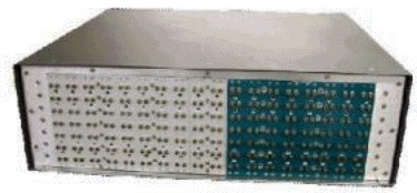
The eight working inputs are numbered from left to right. The two protect are in the middle, and the 8 outputs are on the right.
The picture below is the RF Switch numbering scheme.
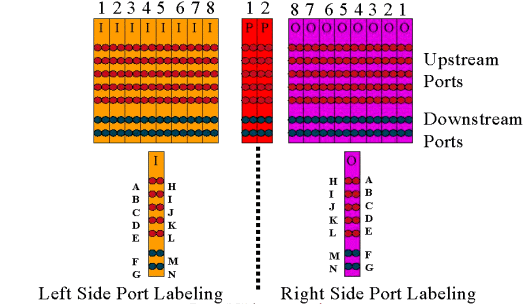
Note: Port N is not used.
The output (colored purple) represents the cable plant. Output 1 is on the far right while Input 1 is on the far left. The ports are mirrored as well. Remember, port N is not used. Just make sure you use consistency on the wiring.
This picture below is the back view of the RF Switch with the 14-port header and special Belden mini-coax cable with MCX connectors.
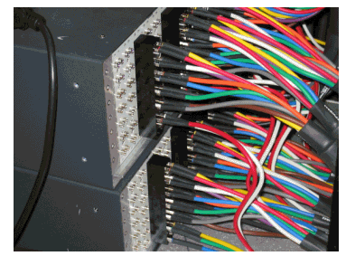
The MCX connectors can be directly attached to the switch, however, you run the risk of loose connections, emissions, and possible intermittent disconnects. Cisco developed a header to resolve these issues.
The MCX connectors snap into the header and there is a special tool shipped with each switch purchase for extraction. The header has two guide pins and will only go in one way. There is a slight bevel on the upper edge to indicate the top of the header. There are two flathead screws to attach the header to the switch. A cable management bracket is also shipped with each RF Switch.
Tip: You can also install the header on the switch, and then insert the MCX connectors into the header. This may make it easier to install. Do not tighten the header to the switch until all connectors are installed.
RF Switch Configuration and Operation
The picture below is a block diagram of the RF Switch.
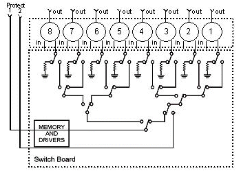
The combiner components are located in the switch chassis, but the relays are in each individual, removable module. Each relay terminates with a 75-ohm load, only in the Protect path, not the in/working path.
Setup serial communication with the switch by consoling in with HyperTerminal or TeraTerm, a console/rollover cable, Cisco 9 pin to RJ-45 adapter, and with a baud rate of 9600.
Set an IP address and mask by issuing the command set ip addr ip add subnet mask . Once this is done, you can Telnet in and also set a Telnet password. Next, set the protection scheme, whether it is 4+1 or 8+1, by issuing the command set prot 4/8. The default is 8+1 where protect 1 covers all eight input slots. In the 4+1 mode, protect 1 covers slots 5-8, and protect 2 covers slots 1-4.
The SNMP community string is private, and can be changed, but not supported in the uBR10K.
Setting Bitmaps
The next important thing to set is the switch-groups, which require hexadecimal bitmaps. The RF Switch bitmap is a total of 32 bits (8 hexadecimal characters) in length, and is calculated as shown below. An Excel calculator is available for use.
Consider group1, which has four US cables wired on the left of an RF Switch header in slot 1, and 1 DS wired to the left side of that same header. The ports used would be ABCDF. For each port that is involved in switching, the corresponding bit is set to 1. If a port is not involved in switching, that port bit is set to 0.
Group 1 is shown below.

Note: The bits 14 to 32 are "do not care" (X).
For group 2, the right side of the header is wired, and the bitmap is shown below.

It is required to set up switch-groups, or the switch will not understand which ports and relays to toggle. When setting up bitmaps, the number can be entered as decimal format, or it must be entered with 0x in front of the hex code for the software to recognize that it is hex. Issue the command set group Group2 0x55100000 to assign the bitmap. Group2 is an alphanumeric word string that must begin with a letter.
Tip: The two bitmaps above are part of the recommended reference design. The 4+1 mode is entirely different, and it is recommended to use the bitmap calculator. If doing a 4+1 protect scheme, you would have four HCCP groups. HCCP groups 1 and 2 in the protect 2 card, and HCCP groups 3 and 4 in the protect 1card. Also, protect 1 covers slots 5-8 on the switch, however, in the uBR configuration those slots are referred to as slots 1-4.
If switching individual ports instead of MAC domains, you must know what protect scheme you are running and use the table below to know which group number to use. Assume the switch is in the 4+1 mode. The command is shown below for the uBR10K.
hccp 1 channel-switch 1 ds rfswitch-module 1.10.84.3 26 1
hccp 1 channel-switch 1 us rfswitch-module 1.10.84.3 10 1
This indicates the IP address of the switch and module 26, which indicates protect card 2 backing up port G in a 4+1 scheme, and module 10, which indicates protect card 2 backing up port C. This is all in slot 1 of the switch.
The table below shows both modes and which number correlates with the respective port.
| 8+1 Mode | 4+1 Mode |
|---|---|
| A(1) H(2) | A(1,2) H(3,4) |
| B(3) I(4) | B(5,6) I(7,8) |
| C(5) J(6) | C(9,10) J(11,12) |
| D(7) K(8) | D(13,14) K(15,16) |
| E(9) L(10) | E(17,18) L(19,20) |
| F(11) M(12) | F(21,22) M(23,24) |
| G(13) N(14) | G(25,26) N(27,28) |
Setting Slot Configuration
The new firmware allows the chassis to be configured for any mix of upstream/downstream cards. This is accomplished by using the new CLI command set slot config USslots DSslots .
The USslots and DSslots parameters are 16-bit hex integer bit-masks representing whether the module is enabled/configured for that type of card, with the right-most bit representing module 1. Refer to the new bitmap calculator for automated configurations.
For example, if you wanted to setup a chassis with four linecards, upstream cards in modules 1-2, and downstream cards in modules 3-4, you would issue the set slot config 0x0003 0X000c command.
The slot configuration is stored on nvmem, separate from the application firmware. This allows future upgrades to the application firmware without requiring the user to reprogram the slot configuration, and allows a single application code distribution for any/all RF Switch configurations.
Normally, the factory would do this configuration when the unit is built, however, this would allow you to change the setup in the field if you like, and to use any number/mix of cards that you might need in the future.
A sample configuration is provided below.
10 upstream/3 downstream/1 empty (current configuration):
                upstream bitmask = 0000 0011 1111 1111 = 0x03ff
                dnstream bitmask = 0001 1100 0000 0000 = 0x1c00

                SET  SLOT  CONFIG  0x03ff  0x1c00

        12 upstream/2 downstream (new configuration):
                upstream bitmask = 0000 1111 1111 1111 = 0x0fff
                dnstream bitmask = 0011 0000 0000 0000 = 0x3000

                SET SLOT CONFIG 0x0fff 0x3000
Testing the RF Switch Relays
Cisco recommends testing the relays once a week and at least once a month. Console or Telnet into the switch and issue the command test module. If a password is set in the RF Switch, issue the password password name command to use the test command. This will test all the relays at once and go back to the normal working mode. Do not use this test command while in the protect mode. Do not use this test command while in the protect mode.
Tip: You can toggle the relays on the switch without affecting the upconverter or any of the modems. This is important if testing the relays without actually switching any of the line cards or corresponding upconverters. If a relay is enabled on the switch and a failover occurs, it will go to the proper state and not just toggle from one state to another.
Issue the command switch 13 1 to test port G on slot 1 of the Switch. You can test an entire bitmap by issuing the switch group name 1 command. Issue the switch group name 0 (or idle) command to disable the relays for normal working mode.
Additionally, the customer should perform a CLI failover test of an HCCP group (issue the hccp g switch m command ) from the CMTS to test the protect card and protect path. This type of failover may take 4-6 seconds, and could cause a small percentage of modems to go offline. Therefore, this test should be performed less often and only during off-peak hours. The above tests will help improve overall system availability.
Upgrading the RF Switch Code
Follow the steps below.
-
Load the new images into the uBR with a Flash disk in slot 0.
-
Configure the commands below in the uBR.
tftp-server disk0: rfsw330-bf-1935022g alias rfsw330-bf-1935022g
tftp-server disk0: rfsw330-fl-1935030h alias rfsw330-fl-1935030h
-
Console into the switch and issue the set tftp-host {ip-addr} command. Use the IP address of the uBR for TFTP transfers.
-
Issue the copy tftp:rfsw330-bf-1935022g bf: command to load the bootflash, and copy tftp:rfsw330-fl-1935030h fl: to load the Flash.
-
Reboot or reload so that the new code runs. Type PASS SYSTEM and Save Config to update the new nvmem fields. Reboot again so that this all takes effect.
 Warning: You may need to reset some of the configuration after reloading, such as the switch IP address. Review your switch configuration after reloading to verify. Once upgraded to version 3.5, a default gateway address can be added to the switch and new upgrades to the switch can be done across subnets remotely. The only limit is if loading from Unix stations, the new image name must be lowercase letters. This new image also adds a DHCP client option and a chassis/module configuration setting.
DHCP Operation
This release includes full support for a DHCP client. DHCP operation is enabled by default, unless the user has set a static IP from the CLI. Commands have been added/enhanced to support DHCP operation.
When the RF Switch boots, it checks to see if DHCP has been enabled. This is done via the CLI in a variety of ways. You can use any of the following commands to enable DHCP:
set ip address dhcp
set ip address ip adress subnet mask
no set ip address

!--- To set the default, since DHCP is now the default.
The RF Switch no longer assumes a static IP of 10.0.0.1 as in versions prior to 3.00.
If enabled, the RF Switch installs the DHCP client and attempts to locate a DHCP server to request a lease. By default, the client requests a lease time of 0xffffffff (infinite lease), but this can be changed by issuing the set dhcp lease leasetime_secs command. Since the actual lease time is granted from the server, this command is primarily used for debug/testing, and should not be required for normal operation.
If a server is located, the client requests settings for IP address and subnet mask, a gateway address, and the location of a TFTP server. The gateway address is taken from option 3 (router option). The TFTP server address can be specified in a number of ways. The client checks the next-server option (siaddr), option 66 (TFTP server name), and option 150 (TFTP server address). If all three of the above are absent, the TFTP server address defaults to the DHCP server address. If the server grants a lease, the DHCP client records the offered lease time for renewal, and continues with the boot process, installing the other network applications (Telnet and SNMP), and the CLI.
If a server is not located within 20-30 seconds, the DHCP client is suspended, and the CLI runs. The DHCP client will run in the background attempting to contact a server approximately every five seconds until a server is located, a static IP is assigned via the CLI, or the system is rebooted.
The CLI allows the user to override any of the network settings that may be received via the server, and assign static values for these settings. All of the set xxx command parameters are stored in nvmem, and are used across reboots. Since the current network settings may now come from either DHCP or the CLI, a few changes/new commands have been implemented. The existing show config command has been changed to show the settings of all the nvmem parameters, which are not necessarily the ones in effect at the time.
To obtain the current network parameters in use, the new command show ip has been added. In addition to the network settings, this command also shows the current IP mode (static versus DHCP), the status of the DHCP client, and the status of the Telnet and SNMP applications (which are only started if a valid IP exists).
An additional command, show dhcp, has been added for informational purposes. This command shows the values received from the DHCP server, as well as the status of the lease time. The time values shown are in the format HH:MM:SS, and are relative to the current system time, which is also displayed.
Assignment of static values for any of the configurable network parameters should go into effect immediately and override the current setting without further action. This allows some of the parameters to remain dynamic, while fixing others. For example, DHCP could be used to obtain the IP address, while retaining the setting for the TFTP server set via the CLI. The one exception to this is when going from using a static IP to DHCP. Since the DHCP client is only installed at boot-up as required, transitioning from a static IP to DHCP requires the system to be rebooted for DHCP to take effect.
LEDs
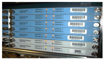
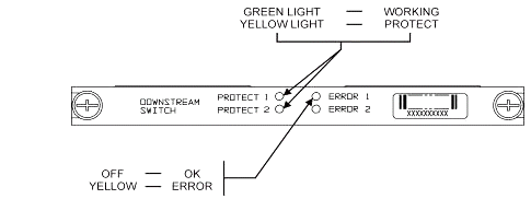
The corresponding module LEDs will turn from green to amber/yellow. The layout is opposite from the back, meaning if the switch-group on the left of the header in slot 1 of the switch fails-over in an 8+1 mode, the protect 1 LEDs on the right will go from green to amber to show the relays have toggled.
The picture below shows the color differences on the LEDs and does not represent a specific failover.
-
LED #1 Green/Yellow to indicate working/protect 1
-
LED #2 Green /Yellow to indicate working/protect 2
-
LED #3 Off/Yellow to indicate a problem on channel 1
-
LED #4 Off/Yellow to indicate a problem on channel 2
The module diagram is shown below.
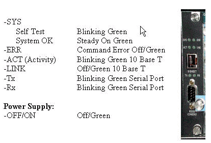
The picture below shows the Ethernet controller indicators.
Customer Issues and Applications
Some points that may be considered issues are the cost, utilization of all the components, insertion loss, physical layout, small connectors and cable, and availability and support of these components.
The insertion loss of 6 dB while in the working mode could be an issue. There is also more insertion loss (about 1-2 dB) when the switch goes into the protect mode. This depends on what frequency you are using for DS. US insertion loss is about 4.5 dB.
Industry acceptance may take time in regards to the smaller MCX connectors and the smaller coaxial cable being used for the solution. AOL Time Warner decided to buy 10,000 feet of this style of cable to rewire some of the US cabling in their headends. Charter is using this cabling now also. If they start using the cable, it will just be a matter of time before they and other manufactures start using the new smaller connector as well. VCom’s new upconverter uses MCX connectors now.
WhiteSands Engineering produce the cable kits for Cisco. Cisco must stock a minimum style of cable kits to satisfy our recommended design. You can go to WhiteSands directly for special cable orders. You can get the required tools for connectorization from CablePrep or WhiteSands.
The RF Switch part number is case-sensitive. You have to enter uBR-RFSW to order the switch.
Operational Issues
Consider the situations described below.
A 5x20 line card goes bad, and the protect line card takes over. You disconnect the faulty line card, and the DS signal from the protect linecard back-feeds to the end of the disconnected cable that used to be hooked up to the other line card and is now not terminated.
This will cause an impedance mismatch, and reflective energy that will be about 7 dB down from the original signal. This is because the splitter in the switch chassis will only have about 7 dB of isolation when the common port is not terminated. The affected frequencies will be related to the physical length of the cable that was disconnected.
This idea will help to mitigate the potential hazard of the DS level changing by up to 3 dB:
-
Terminate the DS cables with 75 ohm terminators. Special MCX terminators may be needed.
In another situation, RF Switch Telnet access from the uBR10K console creates double entries when typing. A work around is to disable local echo. For example, from the CLI issue telnet ip address /noecho. You need to press control break to get out, or control ] for Telnet command mode, and type quit or send break. Another way to disconnect is to press Control+shift+6+x, and type disc 1 from the uBR command line. For some standard break sequences, refer to Standard Break Key Sequence Combinations During Password Recovery.
Obscure Applications
Consider the situation described below.
The protect US cables on the uBR can be used to test the signal strength for the corresponding working. For example, assume that you have the switch in 8+1 mode, a working blade in slot 8/0 of the uBR, a protect blade in slot 8/1, and the working wired up to slot 1 of the switch. To test the US power level at US0 of card 8/0, Telnet or console in the switch and issue the switch 1 1 command. This will activate the relay from slot 1 of the switch for Module 1, which is also known as port A of the switch. Disconnect the cable on US0 of the protect blade and attach to a spectrum analyzer. You will be able to test the US signal that is actually going to the working US0.
Show Commands
Use the commands below to troubleshoot.
show version
rfswitch>sh ver
     Controller firmware:
       RomMon: 1935033  V1.10
       Bootflash: 1935022E  V2.20
       Flash: 1935030F  V3.50
       Slot          Model       Type        SerialNo  HwVer SwVer    Config
        999            193-5001   10BaseT    1043      E     3.50
          1            193-5002   upstream   1095107   F     1.30    upstream
          2            193-5002   upstream   1095154   F     1.30    upstream
          3            193-5002   upstream   1095156   F     1.30    upstream
          4            193-5002   upstream   1095111   F     1.30    upstream
          5            193-5002   upstream   1095192   F     1.30    upstream
          6            193-5002   upstream   1095078   F     1.30    upstream
          7            193-5002   upstream   1095105   F     1.30    upstream
          8            193-5002   upstream   1095161   F     1.30    upstream
          9            193-5002   upstream   1095184   F     1.30    upstream
         10            193-5002   upstream   1095113   F     1.30    upstream
         11            193-5003   dnstream   1095361   J     1.30    dnstream
         12            193-5003   dnstream   1095420   J     1.30    dnstream
         13            193-5003   dnstream   1095417   J     1.30    dnstream
show module all
rfswitch>show module all
Module      Presence    Admin      Fault
1            online         0       ok
2            online         0       ok
3            online         0       ok
4            online         0       ok
5            online         0       ok
6            online         0       ok
7            online         0       ok
8            online         0       ok
9            online         0       ok
10           online         0       ok
11           online         0       ok
12           online         0       ok
13           online         0       ok
show config
rfswitch>show config
     IP addr: 10.10.3.3
     Subnet mask: 255.255.255.0
     MAC addr: 00-03-8F-01-04-13
     Gateway IP: 10.10.3.170
     TFTP host IP: 172.18.73.165
     DHCP lease time: infinite
     TELNET inactivity timeout: 600 secs
     Password: xxxx
     SNMP Community: private
     SNMP Traps: Enabled
     SNMP Trap Interval: 300 sec(s)
     SNMP Trap Hosts: 1
       172.18.73.165
     Card Protect Mode: 8+1
     Protect Mode Reset: Disabled
     Slot Config: 0x03ff 0x1c00 (13 cards)
     Watchdog Timeout: 20 sec(s)
     Group definitions: 5
     ALL     0xffffffff
     GRP1    0xaa200000
     GRP2    0x55100000
     GRP3    0x00c80000
     GRP4    0x00c00000
RF Switch Specifications
The list below shows the RF Switch specifications.
-
Input Power AC — 100 to 240 Vac, 50/60 Hz, Operating Range — 90-254 Vac
-
DC Power — Three Terminal Block -48/-60 Vdc, Range — -40.5 to -72 Vdc, 200 mVpp ripple/noise
-
Temperature Range — 0 to +40° C, Operating Temperature Range — -5 to +55° C
-
Unit Control 10BaseT SNMP Ethernet and RS-232 Bus — 9-pin male D
-
RF Connectors — MCX, Impedance — 75 ohms
-
Max RF Input Power — +15 dBm (63.75 dBmV)
-
Switch Type — Electro-mech, absorptive for Working path, non-absorptive on protect path
-
DS Frequency Range — 54 to 860 MHz
-
Max DS Insertion Loss — 5.5 dB from working to output, 8.0 dB from protect to output
-
DS Insertion Loss Flatness — +1.1 dB from working to output, +2.1 dB from protect to output
-
DS Output Return Loss — greater than 15.5 dB
-
DS Isolation — greater than 60 dB working to working, greater than 20 dB from working to respective protect when in protect mode, and greater than 60 dB from working to protect when in working mode
-
Upstream Frequency Range — 5 to 70 MHz
-
Maximum Upstream Insertion Loss — 4.1 dB from input to working, 5.2 dB from input to protect
-
US Insertion Loss Flatness — + 0.4 dB from input to working, + 0.6 dB from input to protect
-
US Input Return Loss — greater than 16 dB
-
US Isolation — greater than 60 dB working to working, greater than 20 dB from working to respective protect when in protect mode, and greater than 60 dB from working to protect when in working mode
-
Physical Form Factor — 19 x 15.5 x 5.25 (482mm x 394mm x 133mm), Weight — 36 lbs
Related Information
Contact Cisco
- Open a Support Case

- (Requires a Cisco Service Contract)
 Feedback