Konfigurationsbeispiel für FlexVPN HA Dual-Hub
Download-Optionen
-
ePub (509.5 KB)
In verschiedenen Apps auf iPhone, iPad, Android, Sony Reader oder Windows Phone anzeigen
Inklusive Sprache
In dem Dokumentationssatz für dieses Produkt wird die Verwendung inklusiver Sprache angestrebt. Für die Zwecke dieses Dokumentationssatzes wird Sprache als „inklusiv“ verstanden, wenn sie keine Diskriminierung aufgrund von Alter, körperlicher und/oder geistiger Behinderung, Geschlechtszugehörigkeit und -identität, ethnischer Identität, sexueller Orientierung, sozioökonomischem Status und Intersektionalität impliziert. Dennoch können in der Dokumentation stilistische Abweichungen von diesem Bemühen auftreten, wenn Text verwendet wird, der in Benutzeroberflächen der Produktsoftware fest codiert ist, auf RFP-Dokumentation basiert oder von einem genannten Drittanbieterprodukt verwendet wird. Hier erfahren Sie mehr darüber, wie Cisco inklusive Sprache verwendet.
Informationen zu dieser Übersetzung
Cisco hat dieses Dokument maschinell übersetzen und von einem menschlichen Übersetzer editieren und korrigieren lassen, um unseren Benutzern auf der ganzen Welt Support-Inhalte in ihrer eigenen Sprache zu bieten. Bitte beachten Sie, dass selbst die beste maschinelle Übersetzung nicht so genau ist wie eine von einem professionellen Übersetzer angefertigte. Cisco Systems, Inc. übernimmt keine Haftung für die Richtigkeit dieser Übersetzungen und empfiehlt, immer das englische Originaldokument (siehe bereitgestellter Link) heranzuziehen.
Inhalt
Einführung
In diesem Dokument wird beschrieben, wie Sie ein Design für vollständige Redundanz für Außenstellen konfigurieren, die über ein IPSec-basiertes VPN über ein unsicheres Netzwerkmedium (z. B. das Internet) mit einem Rechenzentrum verbunden sind.
Voraussetzungen
Anforderungen
Für dieses Dokument bestehen keine speziellen Anforderungen.
Verwendete Komponenten
Die Informationen in diesem Dokument basieren auf den folgenden Technologiekomponenten:
- Border Gateway Protocol (BGP) als Routing-Protokoll innerhalb des Rechenzentrums und zwischen Stationen und Hubs im VPN-Overlay
- Bidirectional Forwarding Detection (BFD) als Mechanismus zur Erkennung von Downlinks (Router Down), die nur innerhalb des Rechenzentrums (nicht über den Overlay-Tunneln) ausgeführt werden.
- Cisco IOS® FlexVPN zwischen den Hubs und den Stationen mit Spoke-to-Spoke-Funktionen, die über Switching-Kurzwahlfunktionen bereitgestellt werden.
- Generic Routing Encapsulation (GRE)-Tunneling zwischen zwei Hubs, um Spoke-to-Spoke-Kommunikation zu ermöglichen, selbst wenn die Stationen mit verschiedenen Hubs verbunden sind.
- Erweiterte Objektverfolgung und statische Routen, die an die verfolgten Objekte gebunden sind.
Die Informationen in diesem Dokument wurden von den Geräten in einer bestimmten Laborumgebung erstellt. Alle in diesem Dokument verwendeten Geräte haben mit einer leeren (Standard-)Konfiguration begonnen. Wenn Ihr Netzwerk in Betrieb ist, stellen Sie sicher, dass Sie die potenziellen Auswirkungen eines Befehls verstehen.
Hintergrundinformationen
Wenn Sie Lösungen für den Remote-Zugriff für das Rechenzentrum entwerfen, ist Hochverfügbarkeit (HA) häufig eine der Hauptanforderungen für geschäftskritische Benutzeranwendungen.
Die in diesem Dokument vorgestellte Lösung ermöglicht eine schnelle Erkennung und Wiederherstellung nach Fehlerszenarien, in denen einer der VPN-terminierenden Hubs aufgrund eines erneuten Ladens, Upgrades oder Energieproblems ausfällt. Alle Router in den Außenstellen (Spokes) verwenden den anderen operativen Hub sofort, wenn ein solcher Ausfall erkannt wird.
Die Vorteile dieses Designs:
- Schnelle Netzwerkwiederherstellung von einem VPN-Hub-Down-Szenario
- Keine komplizierten Stateful-Synchronisierungen (z. B. IPSec Security Associations (SAs), Internet Security Association and Key Management Protocol (ISAKMP) SAs und Crypto-Routing) zwischen den VPN-Hubs
- Keine Probleme bei der Wiedergabe aufgrund von Verzögerungen bei der Synchronisierung der ESP-Sequenznummer (Encapsulating Security Payload) mit IPSec Stateful HA
- VPN-Hubs können verschiedene Hardware oder Software auf der Basis von Cisco IOS/IOS-XE verwenden.
- Flexible Implementierungsoptionen für Lastenausgleich mit BGP als Routing-Protokoll, das im VPN-Overlay ausgeführt wird
- Klare und lesbare Weiterleitung auf allen Geräten ohne versteckte Mechanismen, die im Hintergrund ausgeführt werden
- Direkte Spoke-to-Spoke-Verbindung
- Alle FlexVPN-Vorteile, einschließlich AAA-Integration (Authentication, Authorization, Accounting) und Quality of Service (QoS) pro Tunnel
Konfigurieren
Dieser Abschnitt enthält Beispielszenarien und beschreibt die Konfiguration eines Designs für vollständige Redundanz für Außenstellen, die über ein unsicheres Netzwerkmedium eine Verbindung mit dem Rechenzentrum über ein IPSec-basiertes VPN herstellen.
Hinweis: Verwenden Sie das Command Lookup Tool (nur registrierte Kunden), um weitere Informationen zu den in diesem Abschnitt verwendeten Befehlen zu erhalten.
Netzwerkdiagramm
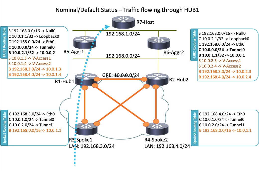
Dies ist die Netzwerktopologie, die in diesem Dokument verwendet wird:

Hinweis: Auf allen Routern, die in dieser Topologie verwendet werden, wird Cisco IOS Version 15.2(4)M1 ausgeführt, und die Internet Cloud verwendet ein Adressschema von 172.16.0.0/24.
Reguläres Betriebsszenario
Wenn alle Router betriebsbereit sind, leiten alle Spoke-Router im normalen Betriebszustand den gesamten Datenverkehr über den Standard-Hub (R1-HUB1) weiter. Diese Routing-Präferenz wird erreicht, wenn die lokale Standard-BGP-Präferenz auf 200 festgelegt ist (Einzelheiten hierzu in den folgenden Abschnitten). Dies kann je nach den Bereitstellungsanforderungen, z. B. dem Lastenausgleich des Datenverkehrs, angepasst werden.
Spoke-to-Spoke (Tastenkombination)
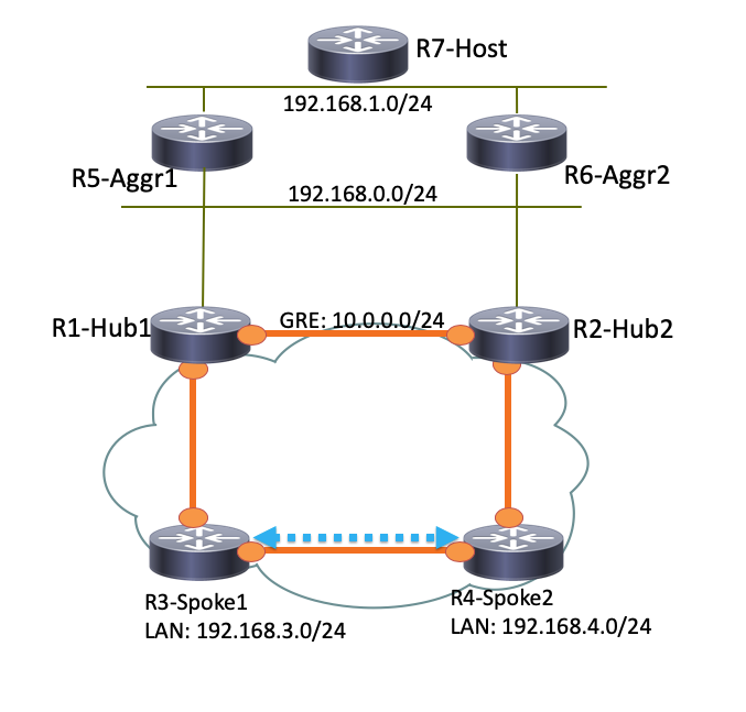
Wenn R3-Spoke1 eine Verbindung mit R4-Spoke2 initiiert, wird mit der kurzgefassten Switching-Konfiguration ein dynamischer Spoke-to-Spoke-Tunnel erstellt.
Tipp: Weitere Informationen finden Sie im Konfigurationsleitfaden zur Konfiguration von FlexVPN Spoke to Spoke.
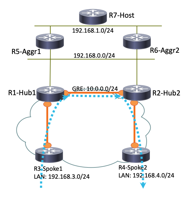
Wenn R3-Spoke1 nur mit R1-HUB1 und R4-Spoke2 nur mit R2-HUB2 verbunden ist, kann mit dem Point-to-Point GRE-Tunnel, der zwischen den Hubs verläuft, weiterhin eine direkte Spoke-to-Spoke-Verbindung hergestellt werden. In diesem Fall sieht der ursprüngliche Datenverkehrspfad zwischen R3-Spoke1 und R4-Spoke2 ähnlich aus wie folgt:

Da R1-Hub1 das Paket an die virtuelle Zugriffsschnittstelle empfängt, die dieselbe NHRP-Netzwerk-ID (Next Hop Resolution Protocol) wie der GRE-Tunnel hat, wird die Verkehrsanzeige an den R3-Spoke1 gesendet. Dies löst die Erstellung dynamischer Spoke-to-Spoke-Tunnel aus:

Routingtabellen und -ausgänge für ein reguläres Betriebsszenario
Die Routing-Tabelle R1-HUB1 in einem normalen Betriebsszenario sieht wie folgt aus:
R1-HUB1# show ip route
Codes: L - local, C - connected, S - static, R - RIP, M - mobile, B - BGP
       D - EIGRP, EX - EIGRP external, O - OSPF, IA - OSPF inter area
       N1 - OSPF NSSA external type 1, N2 - OSPF NSSA external type 2
       E1 - OSPF external type 1, E2 - OSPF external type 2
       i - IS-IS, su - IS-IS summary, L1 - IS-IS level-1, L2 - IS-IS level-2
       ia - IS-IS inter area, * - candidate default, U - per-user static route
       o - ODR, P - periodic downloaded static route, H - NHRP, l - LISP
       a - application route
       + - replicated route, % - next hop override

Gateway of last resort is not set

      10.0.0.0/8 is variably subnetted, 11 subnets, 3 masks
S        10.0.0.0/8 is directly connected, Null0
C        10.0.0.0/24 is directly connected, Tunnel0
L        10.0.0.1/32 is directly connected, Tunnel0
C        10.0.1.1/32 is directly connected, Loopback0
S        10.0.1.2/32 is directly connected, Virtual-Access1
S        10.0.1.3/32 is directly connected, Virtual-Access2
B        10.0.2.1/32 [200/0] via 10.0.0.2, 00:05:40
B        10.0.2.3/32 [200/0] via 10.0.0.2, 00:05:40
B        10.0.2.4/32 [200/0] via 10.0.0.2, 00:05:40
B        10.0.5.1/32 [200/0] via 192.168.0.5, 00:05:40
B        10.0.6.1/32 [200/0] via 192.168.0.6, 00:05:40
      172.16.0.0/16 is variably subnetted, 2 subnets, 2 masks
C        172.16.0.0/24 is directly connected, Ethernet0/0
L        172.16.0.1/32 is directly connected, Ethernet0/0
S     192.168.0.0/16 is directly connected, Null0
      192.168.0.0/24 is variably subnetted, 2 subnets, 2 masks
C        192.168.0.0/24 is directly connected, Ethernet0/2
L        192.168.0.1/32 is directly connected, Ethernet0/2
B     192.168.1.0/24 [200/0] via 192.168.0.5, 00:05:40
B     192.168.3.0/24 [200/0] via 10.0.1.4, 00:05:24
B     192.168.4.0/24 [200/0] via 10.0.1.5, 00:05:33
Hier sehen Sie die Routing-Tabelle R3-SPOKE1 in einem normalen Betriebsszenario, nachdem der Spoke-to-Spoke-Tunnel mit R4-SPOKE2 erstellt wurde:
R3-SPOKE1#  show ip route
Codes: L - local, C - connected, S - static, R - RIP, M - mobile, B - BGP
       D - EIGRP, EX - EIGRP external, O - OSPF, IA - OSPF inter area
       N1 - OSPF NSSA external type 1, N2 - OSPF NSSA external type 2
       E1 - OSPF external type 1, E2 - OSPF external type 2
       i - IS-IS, su - IS-IS summary, L1 - IS-IS level-1, L2 - IS-IS level-2
       ia - IS-IS inter area, * - candidate default, U - per-user static route
       o - ODR, P - periodic downloaded static route, H - NHRP, l - LISP
       a - application route
       + - replicated route, % - next hop override

Gateway of last resort is not set

      10.0.0.0/8 is variably subnetted, 8 subnets, 2 masks
B        10.0.0.0/8 [200/0] via 10.0.1.1, 00:06:27
H        10.0.0.1/32 is directly connected, 00:06:38, Tunnel1
S   %    10.0.1.1/32 is directly connected, Tunnel0
C        10.0.1.3/32 is directly connected, Tunnel0
H        10.0.1.4/32 is directly connected, 00:01:30, Virtual-Access1
S        10.0.2.1/32 is directly connected, Tunnel1
C        10.0.2.3/32 is directly connected, Tunnel1
H        10.0.2.4/32 [250/1] via 10.0.2.3, 00:01:30, Virtual-Access1
      172.16.0.0/16 is variably subnetted, 2 subnets, 2 masks
C        172.16.0.0/24 is directly connected, Ethernet0/0
L        172.16.0.3/32 is directly connected, Ethernet0/0
B     192.168.0.0/16 [200/0] via 10.0.1.1, 00:06:27
      192.168.3.0/24 is variably subnetted, 2 subnets, 2 masks
C        192.168.3.0/24 is directly connected, Ethernet0/1
L        192.168.3.3/32 is directly connected, Ethernet0/1
      192.168.4.0/32 is subnetted, 1 subnets
H        192.168.4.4 [250/1] via 10.0.1.3, 00:01:30, Virtual-Access1
Auf R3-Spoke1 hat die BGP-Tabelle zwei Einträge für das 192.168.0.0/16-Netzwerk mit unterschiedlichen lokalen Voreinstellungen (R1-Hub1 wird bevorzugt):
R3-SPOKE1#show ip bgp 192.168.0.0/16
BGP routing table entry for 192.168.0.0/16, version 8
Paths: (2 available, best #2, table default)
  Not advertised to any peer
  Refresh Epoch 1
  Local
    10.0.2.1 from 10.0.2.1 (10.0.2.1)
      Origin incomplete, metric 0, localpref 100, valid, internal
      rx pathid: 0, tx pathid: 0
  Refresh Epoch 1
  Local
    10.0.1.1 from 10.0.1.1 (10.0.1.1)
      Origin incomplete, metric 0, localpref 200, valid, internal, best
      rx pathid: 0, tx pathid: 0x0
Die Routing-Tabelle R5-AGGR1 in einem normalen Betriebsszenario sieht wie folgt aus:
R5-LAN1#show ip route
      10.0.0.0/8 is variably subnetted, 10 subnets, 3 masks
B        10.0.0.0/8 [200/0] via 192.168.0.1, 00:07:22
B        10.0.0.0/24 [200/0] via 192.168.0.1, 00:07:22
B        10.0.1.1/32 [200/0] via 192.168.0.1, 00:07:22
B        10.0.1.3/32 [200/0] via 192.168.0.1, 00:07:17
B        10.0.1.4/32 [200/0] via 192.168.0.1, 00:07:16
B        10.0.2.1/32 [200/0] via 192.168.0.2, 15:44:13
B        10.0.2.3/32 [200/0] via 192.168.0.2, 15:44:13
B        10.0.2.4/32 [200/0] via 192.168.0.2, 15:44:13
C        10.0.5.1/32 is directly connected, Loopback0
B        10.0.6.1/32 [200/0] via 192.168.0.6, 00:07:22
      172.16.0.0/24 is subnetted, 1 subnets
B        172.16.0.0 [200/0] via 192.168.0.1, 00:07:22
B     192.168.0.0/16 [200/0] via 192.168.0.1, 00:07:22
      192.168.0.0/24 is variably subnetted, 2 subnets, 2 masks
C        192.168.0.0/24 is directly connected, Ethernet0/0
L        192.168.0.5/32 is directly connected, Ethernet0/0
      192.168.1.0/24 is variably subnetted, 2 subnets, 2 masks
C        192.168.1.0/24 is directly connected, Ethernet0/1
L        192.168.1.5/32 is directly connected, Ethernet0/1
B     192.168.3.0/24 [200/0] via 10.0.1.3, 00:07:06
B     192.168.4.0/24 [200/0] via 10.0.1.4, 00:07:15
Die Routing-Tabelle für R7-HOST ist in einem normalen Betriebsszenario dargestellt:
R7-HOST#show ip route
S*    0.0.0.0/0 [1/0] via 192.168.1.254
      192.168.1.0/24 is variably subnetted, 2 subnets, 2 masks
C        192.168.1.0/24 is directly connected, Ethernet0/0
L        192.168.1.7/32 is directly connected, Ethernet0/0
HUB1-Fehlerszenario
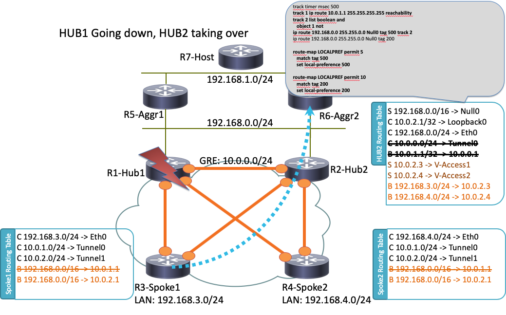
Im Folgenden sehen Sie ein R1-HUB1-Ausfallszenario (aufgrund von Aktionen wie Stromausfällen oder einem Upgrade):

In diesem Szenario tritt diese Ereignissequenz auf:
- Der BFD auf R2-HUB2 und den LAN Aggregat Routern R5-AGGR1 und R6-AGGR2 erkennt den Abwärtsstatus von R1-HUB1. Infolgedessen fällt die BGP-Nachbarschaft sofort aus.
- Die Gleisobjekterkennung für R2-HUB2, die das Vorhandensein des R1-HUB1-Loopbacks erkennt, fällt aus (Track 1 in der Beispielkonfiguration).
- Dieses nachverfolgte Objekt löst einen weiteren Titel aus (Logical NOT). In diesem Beispiel geht Track 2 immer dann hoch, wenn Track 1 ausfällt.
- Dadurch wird ein statischer IP-Routing-Eintrag zur Routing-Tabelle hinzugefügt, da der Wert niedriger ist als die standardmäßige administrative Distanz. Die entsprechende Konfiguration ist hier aufgeführt:
! Routes added when second HUB is down
ip route 10.0.0.0 255.0.0.0 Null0 tag 500 track 2
ip route 192.168.0.0 255.255.0.0 Null0 tag 500 track 2

! Default static routes are with Tag 200 and admin distance of 150
ip route 10.0.0.0 255.0.0.0 Null0 150 tag 200
ip route 192.168.0.0 255.255.0.0 Null0 150 tag 200 - R2-HUB2 verteilt diese statischen Routen mit einer lokalen BGP-Präferenz, die größer ist als der für R1-HUB1 festgelegte Wert. In diesem Beispiel wird im Fehlerszenario eine lokale Präferenz von 500 anstelle des 200 verwendet, der durch R1-HUB1 festgelegt wird:
route-map LOCALPREF permit 5
 match tag 500
 set local-preference 500
!
route-map LOCALPREF permit 10
 match tag 200
 set local-preference 200
!
Auf R3-Spoke1 wird dies in den BGP-Ausgaben angezeigt. Beachten Sie, dass der Eintrag zu R1 noch vorhanden ist, aber nicht verwendet wird:
R3-SPOKE1#show ip bgp 192.168.0.0/16
BGP routing table entry for 192.168.0.0/16, version 10
Paths: (2 available, best #1, table default)
  Not advertised to any peer
  Refresh Epoch 1
  Local
    10.0.2.1 from 10.0.2.1 (10.0.2.1)
      Origin incomplete, metric 0, localpref 500, valid, internal, best
      rx pathid: 0, tx pathid: 0x0
  Refresh Epoch 1
  Local
    10.0.1.1 from 10.0.1.1 (10.0.1.1)
      Origin incomplete, metric 0, localpref 200, valid, internal
rx pathid: 0, tx pathid: 0 - An diesem Punkt beginnen beide Stationen (R3-Spoke1 und R4-Spoke2), Datenverkehr an R2-HUB2 zu senden. Alle diese Schritte sollten innerhalb einer Sekunde ausgeführt werden. Die Routing-Tabelle auf Spoke 3 sieht wie folgt aus:
R3-SPOKE1#show ip route
      10.0.0.0/8 is variably subnetted, 5 subnets, 2 masks
B        10.0.0.0/8 [200/0] via 10.0.2.1, 00:00:01
S        10.0.1.1/32 is directly connected, Tunnel0
C        10.0.1.3/32 is directly connected, Tunnel0
S        10.0.2.1/32 is directly connected, Tunnel1
C        10.0.2.3/32 is directly connected, Tunnel1
      172.16.0.0/16 is variably subnetted, 2 subnets, 2 masks
C        172.16.0.0/24 is directly connected, Ethernet0/0
L        172.16.0.3/32 is directly connected, Ethernet0/0
B     192.168.0.0/16 [200/0] via 10.0.2.1, 00:00:01
      192.168.3.0/24 is variably subnetted, 2 subnets, 2 masks
C        192.168.3.0/24 is directly connected, Ethernet0/1
L 192.168.3.3/32 is directly connected, Ethernet0/1 - Später werden BGP-Sitzungen zwischen den Spokes und R1-HUB1 deaktiviert, und Dead Peer Detection (DPD) entfernt die IPSec-Tunnel, die auf R1-HUB1 terminiert werden. Dies hat jedoch keine Auswirkungen auf die Weiterleitung des Datenverkehrs, da R2-HUB2 bereits als Haupt-Tunnelterminierungsgateway verwendet wird:
R3-SPOKE1#show ip bgp 192.168.0.0/16
BGP routing table entry for 192.168.0.0/16, version 10
Paths: (1 available, best #1, table default)
  Not advertised to any peer
  Refresh Epoch 1
  Local
    10.0.2.1 from 10.0.2.1 (10.0.2.1)
      Origin incomplete, metric 0, localpref 500, valid, internal, best
      rx pathid: 0, tx pathid: 0x0
Konfigurationen
Dieser Abschnitt enthält Beispielkonfigurationen für die Hubs und Stationen, die in dieser Topologie verwendet werden.
R1-HUB-Konfiguration
version 15.4
!
hostname R1-HUB1
!
aaa new-model
!
aaa authorization network default local
!
aaa session-id common
!
! setting track timers to the lowest possible (the lower this value is
! the faster router will react
track timer ip route msec 500
!
! Monitoring of HUB2's loopback present in routing table
! If it is present it will mean that HUB2 is alive
track 1 ip route 10.0.2.1 255.255.255.255 reachability
!
! Monitoring of loopback of R5-AGGR-1
track 3 ip route 10.0.5.1 255.255.255.255 reachability
!
! Monitoring of loopback of R6-AGGR-2
track 4 ip route 10.0.6.1 255.255.255.255 reachability
!
! Track 2 should be UP only when HUB2 is not available and both AGGRE routers are up
!
track 2 list boolean and
 object 1 not
 object 3
 object 4
!

! IKEv2 Config Exchange configuration (IP addresses for spokes are assigned from pool)
crypto ikev2 authorization policy default
 pool SPOKES
 route set interface
 route accept any tag 20
!
!
! IKEv2 profile for Spokes - Smart Defaults used
crypto ikev2 profile default
 match identity remote any
 authentication remote pre-share key cisco
 authentication local pre-share key cisco
 aaa authorization group psk list default default
 virtual-template 1
!
interface Loopback0
 ip address 10.0.1.1 255.255.255.255
!
! GRE Tunnel configured to second HUB. It is required for spoke-to-spoke connectivity
! to work in all possible circumstances
! no BFD echo configuration is required to avoid Traffic Indication sent by remote HUB
! (BFD echo is having the same source and destination IP address)
!
interface Tunnel0
 ip address 10.0.0.1 255.255.255.0
 ip nhrp network-id 1
 ip nhrp redirect
 bfd interval 50 min_rx 50 multiplier 3
 no bfd echo
 tunnel source Ethernet0/2
 tunnel destination 192.168.0.2
!
interface Ethernet0/0
 ip address 172.16.0.1 255.255.255.0
!
interface Ethernet0/2
 ip address 192.168.0.1 255.255.255.0
 bfd interval 50 min_rx 50 multiplier 5
!
interface Virtual-Template1 type tunnel
 ip unnumbered Loopback0
 ip nhrp network-id 1
 ip nhrp redirect
 tunnel protection ipsec profile default
!
! BGP Configuration
router bgp 1
 bgp log-neighbor-changes
! dynamic peer-groups are used for AGGR routers and SPOKES
 bgp listen range 192.168.0.0/24 peer-group DC
 bgp listen range 10.0.1.0/24 peer-group SPOKES
! BGP timers configured
 timers bgp 15 30
 neighbor SPOKES peer-group
 neighbor SPOKES remote-as 1
 neighbor DC peer-group
 neighbor DC remote-as 1
! Within DC BFD is used to determine neighbour status
 neighbor DC fall-over bfd
 neighbor 10.0.0.2 remote-as 1
! BFD is used to detect HUB2 status
 neighbor 10.0.0.2 fall-over bfd
 !
 address-family ipv4
  redistribute connected
! route-map which determines what should be the local-pref
  redistribute static route-map LOCALPREF
  neighbor SPOKES activate
! to spokes only Aggregate/Summary routes are sent
  neighbor SPOKES route-map AGGR out
  neighbor DC activate
  neighbor DC route-reflector-client
  neighbor 10.0.0.2 activate
  neighbor 10.0.0.2 route-reflector-client
 exit-address-family
!
ip local pool SPOKES 10.0.1.2 10.0.1.254
!
! When HUB2 goes down Static Routes with Tag 500 are added and admin distance of 1
ip route 10.0.0.0 255.0.0.0 Null0 tag 500 track 2
ip route 192.168.0.0 255.255.0.0 Null0 tag 500 track 2
! Default static routes are with Tag 200 and admin distance of 150
ip route 10.0.0.0 255.0.0.0 Null0 150 tag 200
ip route 192.168.0.0 255.255.0.0 Null0 150 tag 200
!
!
ip prefix-list AGGR seq 5 permit 192.168.0.0/16
ip prefix-list AGGR seq 10 permit 10.0.0.0/8
!
route-map AGGR permit 10
 match ip address prefix-list AGGR
!
route-map LOCALPREF permit 5
 match tag 500
 set local-preference 500
!
route-map LOCALPREF permit 10
 match tag 200
 set local-preference 200
!
route-map LOCALPREF permit 15
 match tag 20
R2-HUB2-Konfiguration
hostname R2-HUB2
!
aaa new-model
!
aaa authorization network default local
!
track timer ip route msec 500
!
track 1 ip route 10.0.1.1 255.255.255.255 reachability
!
track 2 list boolean and
 object 1 not
 object 3
 object 4
!
track 3 ip route 10.0.5.1 255.255.255.255 reachability
!
track 4 ip route 10.0.6.1 255.255.255.255 reachability
!
!
crypto ikev2 authorization policy default
 pool SPOKES
 route set interface
 route accept any tag 20
!
!
crypto ikev2 profile default
 match identity remote any
 authentication remote pre-share key cisco
 authentication local pre-share key cisco
 aaa authorization group psk list default default
 virtual-template 1
!
!
interface Loopback0
 ip address 10.0.2.1 255.255.255.255
!
interface Tunnel0
 ip address 10.0.0.2 255.255.255.0
 ip nhrp network-id 1
 ip nhrp redirect
 bfd interval 50 min_rx 50 multiplier 3
 no bfd echo
 tunnel source Ethernet0/2
 tunnel destination 192.168.0.1
!
interface Ethernet0/0
 ip address 172.16.0.2 255.255.255.0
!
interface Ethernet0/2
 ip address 192.168.0.2 255.255.255.0
 bfd interval 50 min_rx 50 multiplier 5
!
interface Virtual-Template1 type tunnel
 ip unnumbered Loopback0
 ip nhrp network-id 1
 ip nhrp redirect
 tunnel protection ipsec profile default
!
router bgp 1
 bgp log-neighbor-changes
 bgp listen range 192.168.0.0/24 peer-group DC
 bgp listen range 10.0.2.0/24 peer-group SPOKES
 timers bgp 15 30
 neighbor SPOKES peer-group
 neighbor SPOKES remote-as 1
 neighbor DC peer-group
 neighbor DC remote-as 1
 neighbor DC fall-over bfd
 neighbor 10.0.0.1 remote-as 1
 neighbor 10.0.0.1 fall-over bfd
 !
 address-family ipv4
  redistribute connected
  redistribute static route-map LOCALPREF
  neighbor SPOKES activate
  neighbor SPOKES route-map AGGR out
  neighbor DC activate
  neighbor DC route-reflector-client
  neighbor 10.0.0.1 activate
  neighbor 10.0.0.1 route-reflector-client
 exit-address-family
!
ip local pool SPOKES 10.0.2.2 10.0.2.254
ip forward-protocol nd
!
!
ip route 192.168.0.0 255.255.0.0 Null0 tag 500 track 2
ip route 10.0.0.0 255.0.0.0 Null0 tag 500 track 2
ip route 10.0.0.0 255.0.0.0 Null0 150 tag 200
ip route 192.168.0.0 255.255.0.0 Null0 150 tag 200
!
!
ip prefix-list AGGR seq 5 permit 192.168.0.0/16
ip prefix-list AGGR seq 10 permit 10.0.0.0/8
!
route-map AGGR permit 10
 match ip address prefix-list AGGR
!
route-map LOCALPREF permit 5
 match tag 500
 set local-preference 500
!
route-map LOCALPREF permit 10
 match tag 200
 set local-preference 100
!
route-map LOCALPREF permit 15
 match tag 20
Konfiguration von R3-SPOKE1
hostname R3-SPOKE1
!
aaa new-model
!
aaa authorization network default local
!
!
crypto ikev2 authorization policy default
 route set interface
!
!
crypto ikev2 profile default
 match identity remote any
 authentication remote pre-share key cisco
 authentication local pre-share key cisco
 dpd 10 2 on-demand
 aaa authorization group psk list default default
!
! Tunnel to the HUB1
!
interface Tunnel0
 ip address negotiated
 ip nhrp network-id 1
 ip nhrp shortcut virtual-template 2
 tunnel source Ethernet0/0
 tunnel destination 172.16.0.1
 tunnel protection ipsec profile default
!
! Tunnel to the HUB2
!
interface Tunnel1
 ip address negotiated
 ip nhrp network-id 1
 ip nhrp shortcut virtual-template 2
 tunnel source Ethernet0/0
 tunnel destination 172.16.0.2
 tunnel protection ipsec profile default
!
interface Ethernet0/0
 description INTERNET-CLOUD
 ip address 172.16.0.3 255.255.255.0
!
interface Ethernet0/1
 description LAN
 ip address 192.168.3.3 255.255.255.0
!
interface Virtual-Template2 type tunnel
 ip unnumbered Ethernet0/1
 ip nhrp network-id 1
 ip nhrp shortcut virtual-template 2
 tunnel protection ipsec profile default
!
router bgp 1
 bgp log-neighbor-changes
 timers bgp 15 30
 neighbor 10.0.1.1 remote-as 1
 neighbor 10.0.2.1 remote-as 1
 !
 address-family ipv4
  network 192.168.3.0
  neighbor 10.0.1.1 activate
  neighbor 10.0.2.1 activate
 exit-address-family
Konfiguration von R4-SPOKE2
hostname R4-SPOKE2
!
aaa new-model
!
aaa authorization network default local
!
!
crypto ikev2 authorization policy default
 route set interface
!
crypto ikev2 profile default
 match identity remote any
 authentication remote pre-share key cisco
 authentication local pre-share key cisco
 dpd 10 2 on-demand
 aaa authorization group psk list default default
!
interface Tunnel0
 ip address negotiated
 ip nhrp network-id 1
 ip nhrp shortcut virtual-template 2
 tunnel source Ethernet0/0
 tunnel destination 172.16.0.1
 tunnel protection ipsec profile default
!
interface Tunnel1
 ip address negotiated
 ip nhrp network-id 1
 ip nhrp shortcut virtual-template 2
 tunnel source Ethernet0/0
 tunnel destination 172.16.0.2
 tunnel protection ipsec profile default
!
interface Ethernet0/0
 ip address 172.16.0.4 255.255.255.0
!
interface Ethernet0/1
 ip address 192.168.4.4 255.255.255.0
!
interface Virtual-Template2 type tunnel
 ip unnumbered Ethernet0/1
 ip nhrp network-id 1
 ip nhrp shortcut virtual-template 2
 tunnel protection ipsec profile default
!
router bgp 1
 bgp log-neighbor-changes
 timers bgp 15 30
 neighbor 10.0.1.1 remote-as 1
 neighbor 10.0.2.1 remote-as 1
 !
 address-family ipv4
  network 192.168.4.0
  neighbor 10.0.1.1 activate
  neighbor 10.0.2.1 activate
 exit-address-family
!
R5-AGGR1-Konfiguration
hostname R5-LAN1
!
no aaa new-model
!
!
interface Loopback0
 ip address 10.0.5.1 255.255.255.255
!
interface Ethernet0/0
 ip address 192.168.0.5 255.255.255.0
 bfd interval 50 min_rx 50 multiplier 5
!
! HSRP configuration on the LAN side
!
interface Ethernet0/1
 ip address 192.168.1.5 255.255.255.0
 standby 1 ip 192.168.1.254
!
router bgp 1
 bgp log-neighbor-changes
 neighbor 192.168.0.1 remote-as 1
 neighbor 192.168.0.1 fall-over bfd
 neighbor 192.168.0.2 remote-as 1
 neighbor 192.168.0.2 fall-over bfd
 !
 address-family ipv4
  redistribute connected
  redistribute static
  neighbor 192.168.0.1 activate
  neighbor 192.168.0.2 activate
 exit-address-family
R6-AGGR2-Konfiguration
hostname R6-LAN2
!
interface Loopback0
 ip address 10.0.6.1 255.255.255.255
!
interface Ethernet0/0
 ip address 192.168.0.6 255.255.255.0
 bfd interval 50 min_rx 50 multiplier 5
!
interface Ethernet0/1
 ip address 192.168.1.6 255.255.255.0
 standby 1 ip 192.168.1.254
 standby 1 priority 200
!
router bgp 1
 bgp log-neighbor-changes
 neighbor 192.168.0.1 remote-as 1
 neighbor 192.168.0.1 fall-over bfd
 neighbor 192.168.0.2 remote-as 1
 neighbor 192.168.0.2 fall-over bfd
 !
 address-family ipv4
  redistribute connected
  redistribute static
  neighbor 192.168.0.1 activate
  neighbor 192.168.0.2 activate
 exit-address-family
!
R7-HOST-Konfiguration (Simulation von HOST in diesem Netzwerk)
hostname R7-HOST
!
no aaa new-model
!
interface Ethernet0/0
 ip address 192.168.1.7 255.255.255.0
!
ip route 0.0.0.0 0.0.0.0 192.168.1.254
Wichtige Konfigurationshinweise
Im Folgenden sind einige wichtige Hinweise zu den Konfigurationen aufgeführt, die in den vorherigen Abschnitten beschrieben wurden:
- Der Point-to-Point-GRE-Tunnel zwischen den beiden Hubs ist erforderlich, damit die Spoke-to-Spoke-Konnektivität in allen Szenarien funktioniert. Dies gilt insbesondere für Szenarien, in denen einige der Stationen nur mit einem der Hubs und andere mit einem anderen Hub verbunden sind.
- Die Konfiguration des no bfd echo in der GRE-Tunnelschnittstelle zwischen den beiden Hubs ist erforderlich, um die von einem anderen Hub gesendete Verkehrsanzeige zu vermeiden. Die Quell- und Ziel-IP-Adresse des BFD-Echo ist gleich der IP-Adresse des Routers, der die BFD-Echo sendet. Da diese Pakete vom antwortenden Router zurückgeleitet werden, werden die NHRP-Verkehrsmeldungen generiert.
- In der BGP-Konfiguration ist keine Route-Map-Filterung erforderlich, die die Netzwerke zu Spokes meldet. Die Konfigurationen werden jedoch optimiert, da nur aggregierte/zusammengefasste Routen angekündigt werden:
neighbor SPOKES route-map AGGR out
- An den Hubs ist die Route-Map LOCALPREF-Konfiguration erforderlich, um die richtige lokale BGP-Präferenz einzurichten, und sie filtert die neu verteilten statischen Routen auf die zusammengefassten und IKEv2-Konfigurationsmodus-Routen.
- Dieses Design ist nicht auf Redundanz an Außenstellen ausgelegt (Spoke). Wenn die WAN-Verbindung am Spoke ausfällt, funktioniert das VPN auch nicht. Fügen Sie dem Spoke-Router einen zweiten Link hinzu, oder fügen Sie einen zweiten Spoke-Router am gleichen Standort hinzu, um dieses Problem zu beheben.
Zusammenfassend lässt sich das in diesem Dokument vorgestellte Redundanzdesign als moderne Alternative zur Stateful Switchover (SSO)/Stateful-Funktion behandeln. Sie ist äußerst flexibel und kann genau auf Ihre spezifischen Bereitstellungsanforderungen abgestimmt werden.
Überprüfen
Für diese Konfiguration ist derzeit kein Überprüfungsverfahren verfügbar.
Fehlerbehebung
Für diese Konfiguration sind derzeit keine spezifischen Informationen zur Fehlerbehebung verfügbar.
Zugehörige Informationen
Beiträge von Cisco Ingenieuren
- Piotr KupisiewiczCisco TAC-Techniker
- Wen ZhangCisco TAC-Techniker
- Frederic DetienneCisco TAC-Techniker
Cisco kontaktieren
- Eine Supportanfrage öffnen

- (Erfordert einen Cisco Servicevertrag)
 Feedback